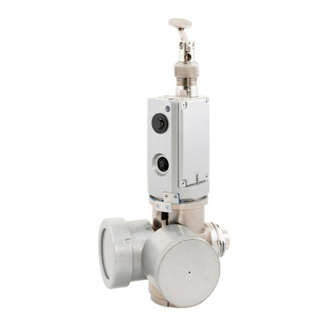
SIAM DU-1 User manual

Tomsk Scientific Industrial Introduction Company “SIAM” LLC
WELL SOUNDERS
«DU-1».
OPERATING MANUAL
Explosion-proof design,
type of explosion protection –intrinsically safe circuit
1Ex ib IIB T3 Gb Хexplosion proof mark
Russia

Well sounders «DU-1»

Well sounders «DU-1»
CONTENTS
1. GENERAL PRODUCT INFORMATION...................................................................6
2. DESIGNATION ..............................................................................................................7
3. BASIC SPECIFICATIONS.............................................................................................8
4. DELIVERY SET .............................................................................................................9
4.1. Ball-type Nozzle .................................................................................................10
4.2 Handle for Installing Well sounder on a Well......................................................10
5. SAFE OPERATION GUIDELINES..............................................................................11
5.1. General Provisions (regulatory framework)............................................................11
5.2. Requirements to Personnel......................................................................................11
5.3. Requirements to Test Objects .................................................................................11
6. ENSURING EXPLOSION-PROOFNESS OF THE PRODUCT..................................13
7. EQUIPMENT INSTALLATION AND DEINSTALLATION ORDER ...................16
7.1. Preparation of Test Objects for Echometry.........................................................16
7.2. Well sounder Installation ....................................................................................16
7.3. Well sounder Removal........................................................................................17
8. BATTERY CHARGE............................................................................................18
9. DEVICE OPERATION IN THE “DB SIAM” SOFTWARE................................19
10. ADDITIONAL ACCESSORIES .................................................................................27
11. MAINTENANCE ........................................................................................................29
11.1. Order of Well sounder Maintenance .....................................................................29
11.2. Procedure of Well sounder Maintenance ..............................................................29
11.2.1. Cleaning Tapered Connecting Thread, Acoustic Sensor, Well sounder and
Sensor Case................................................................................................................29
11.2.2. Exhaust Valve Maintenance...........................................................................31
11.2.3. Cleaning of Accumulator Charging Socket....................................................32

Well sounders «DU-1»
11.2.4. Performance Monitoring................................................................................32
11.2.5. Pressure Testing.............................................................................................32
11.2.6. Replacement of the Valve Sealing Ring ........................................................33
12. DEVICE STORAGE AND TRANSPORTATION .....................................................34
APPENDIX 1. Control of Well Fluid Level in Complicated Conditions ..........................35
APPENDIX 2. Setting Sound Speed Work Sheet..............................................................37
APPENDIX 3. Dependence of Sound Speed on Annular Pressure....................................38
CLAIMS ............................................................................................................................40

Well sounders «DU-1»
The certificate applies to “DU-1” well sounders (hereinafter
referred to as the device) designed for operation at the wellhead in oil and
gas fields.
The device is explosion-proof designed (intrinsically safe circuit
type of protection) in accordance with the requirements of GOST 31610.0-
2014 (IEC 60079-0:2011), GOST 31610.11-2014 (IEC 60079-11.), GOST
31610:2011), and have 1Ex ib IIB T3 Gb Хexplosion proof mark. “DU-
1” well sounder is designed for indoor and outdoor installation in
hazardous areas where atmospheric explosives of IIA, IIB categories and
T1, T2, T3 groups can form according to GOST R IEC 60079-20-1-2011
in the operating temperature range from -40 ºC to +50 ºC. The device
design is comply with the assigned explosion proof mark, with the
requirements of GOST IEC 60079-14-2013 and other regulatory
documents governing the use of electrical equipment in hazardous areas.
The operating manual contains information about the design,
principle of operation and specifications of the device as well as
instructions necessary for proper operation, maintenance, transportation
and storage of the device.
Observe the requirements of the Federal norms and regulations in
the field of industrial safety "Safety rules in oil and gas industry" as well as
this manual, when operating, maintaining and repairing the device.
The device may only be operated by specially trained personnel
who have studied the operating documentation for the device, received the
relevant safety instructions and permission to work.

Well sounders «DU-1»
1. GENERAL PRODUCT INFORMATION
1.1 Please read the operating instructions before using the DDIN-2
sensor.
1.2 The device is explosion-proof designed (intrinsically safe
circuit type of protection) in accordance with the requirements of GOST
31610.0-2014 (IEC 60079-0:2011), GOST 31610.11-2014 (IEC 60079-
11.), GOST 31610:2011), and have 1Ex ib IIB T3 Gb Хexplosion proof
mark. “DU-1” well sounder is designed for indoor and outdoor installation
in hazardous areas where atmospheric explosives of IIA, IIB categories
and T1, T2, T3 groups can form according to GOST R IEC 60079-20-1-
2011 in the operating temperature range from -40 ºC to +50 ºC. The
device design is comply with the assigned explosion proof mark, with the
requirements of GOST IEC 60079-14-2013 and other regulatory
documents governing the use of electrical equipment in hazardous areas.

Well sounders «DU-1»
2. DESIGNATION
The well sounder is designed for
generating acoustic impulses in the annular
space, as well as receiving, converting and
analyzing acoustic responses (echo-signals),
defining fluid level and controlling pressure
at the wellhead.
The well sounder consists of:
1 - the case;
2 - thread connecting coupling;
3 - two shackles;
4 - the rotary retrievable outlet valve;
5 - the ON\OFF button;
6 - the Power LED ;
7 - the Charge LED ;
8 - the plug for charging the in-built
accumulator.
To record an echogram, the sensor is to be installed onto the
measuring connection of the tree; no connecting cables are needed. The
outlet valve can be rotated around the longitudinal axis without restriction
to install the discharge nozzle away from the operator.

Well sounders «DU-1»
3. BASIC SPECIFICATIONS
2.1 The device is designed for operation at the wellhead in oil and
gas fields and provides:
2.1.1 Fluid level measurement in annular space in the range of (20 –
3000) m, excess pressure measurement in the range of (0 –100) kgf/sm2.
2.1.2 Measured data record and saving in a non-volatile storage
device.
2.1.3 The well sounder supports control and transfer of measurement
results to the terminal by means of Bluetooth radio channel (or Zig-
Bee on demand) at a range of at least 35 meters.
2.2 The device maintains its operability at ambient temperatures
from minus 40 C to + 50 C.
2.3 The device operates autonomously and is powered by a special
internal battery type EEMB LP103450LC-PCM-LD with 3.6 V or 3.7 V
voltage. The minimum operating voltage of the battery which does not lead
to a loss of performance of the device is 2.7 V.
2.4 The basic specifications are given in Table 1.
Table 1
Parameter name
Norms on specifications
Explosion proof mark
1Ex ib IIB T3 X
Level control range, m
20 –3000(6000)
Resolution capacity of the level
control (at speed of sound in gas
340 m/s), % URL
0,03
Pressure measurement range,
kgf/sm2
0 –100
Resolution capacity of pressure
control, kgf/sm2
0,1
Permissible sound speed range in
annular gas, m/sec
250 –450

Well sounders «DU-1»
Parameter name
Norms on specifications
Continuous operation time in
registration mode (once a day), hour
35
Max. working power, mW
200
Weight, kg
2,3
4. DELIVERY SET
The device is supplied according to the set shown in Table 2.
Table 2
Title
Q-ty
1. Well sounder «DU-1»
1
2. Certificate
1
3. Operating manual
1
4. “DB Siam 2.5” software user’s guide
1
5. CD with the software
1
6. Package
1
7. Conformity certificate (copy)
1
8. Ball-type nozzle
1
9. Handle for installing Well sounder on a well
1
10. Spare parts for the valve unit:
Ring 020-024-25-2-3
Cone
1
1
11. USB cable
1
12. Network adapter
1
13. Interface cable
1

Well sounders «DU-1»
4.1. Ball-type Nozzle
The ball-type nozzle (the rubber sphere) is
designed for generating an acoustic impulse when
there is no excessive gas pressure in the annular
space of the well. The ball-type nozzle is made up
of the rubber sphere and the coupling. The ball-
type nozzle is actuated by a violent blow of the
hand on the sphere. An acoustic impulse, sufficient for positive control of
the fluid level in wells up to 600…800 m, is formed. After the acoustic
impulse is generated, the rubber sphere should be kept in the position
which it took immediately after the blow until the value of the measured
level pops up on the screen. The ball-type nozzle is screwed on the well
sounder instead of the retrievable manual valve by using the reduction
sleeve supplied with the device.
4.2 Handle for Installing Well sounder on a Well
The handle is used for convenient installation and deinstallation of
the well sounder on a well. Being significantly long and strong, the handle,
equipped with shackles, allows to tighten the well sounder on the
measuring connection with the sufficient torque.

Well sounders «DU-1»
5. SAFE OPERATION GUIDELINES
5.1. General Provisions (regulatory framework)
The design of the wellhead equipment is to be approved by the
Russian Technical Surveillance Agency (RTSA).
Preparation of the well for tests should be conducted in accordance
with the requirements of the current Manual and internal guidelines
for maintaining and testing wells approved by the head of the
company.
Test equipment is to be operated according to the operating
instructions supplied with the equipment.
Measures for ensuring safety are regulated by labor protection
instructions for respective types of work approved by the
Company’s Department of Labour Protection and the Safety
Regulations in Oil and Gas Industry approved by the RTSA.
5.2. Requirements to Personnel
Well tests are to be carried out by individuals above 18 who have
secondary education and who are medically cleared for work.
Personnel are to take professional training followed by knowledge
checking and have a relevant permit category in accordance with
qualification requirements: not below category 5 for oil and gas
production operators; not below category 4 for well test operators.
Personnel are to be trained to work with test equipment.
5.3. Requirements to Test Objects
Pressure measurement and control of fluid level is carried out in oil
and gas producing wells of different operational modes (flowing, gas lift,
artificial lift, etc.), as well as in injection, intake, control and other wells.
Dynamogram control is carried out on rod pumps of all types and
designs.
Wells are to be tied and operated in accordance with the Safety
Regulations in Oil and Gas Industry.

Well sounders «DU-1»
While controlling level, a tested well is to be equipped with an
offset with a valve and an elbow for connecting an echometry
device. Fluid level can be determined only in the space of a well
(tubular, intertubular, annular, borehole annulus) which is
connected with an elbow. The elbow is not to have any abrupt
tapers (chokes, hoppers and similar units).The elbow of the offset
should have pipe tapered thread 60 (State Standard 633-80) and be
located at the height 0.2-1.8 meters above the ground. If the height
exceeds 1.8 meters, fixed or portable platforms are to be used
provided they comply with the Safety Regulations in Oil and Gas
Industry. The elbow which is not used is to be closed with an end
cap. Along the travel path of the sound pulse, there should be no
more than two 90⁰ pipe bends at the distance of 20 meters from the
elbow.

Well sounders «DU-1»
6. ENSURING EXPLOSION-PROOFNESS OF THE
PRODUCT.
6.1. Explosion-proofness of the device is provided by the type of
protection "intrinsically safe electric circuit" “ib” level, according to the
requirements of GOST 31610.11-2014 (IEC 60079-11:2011), which is
achieved by the following:
Basic circuit diagram includes the protective component
“Fib”. The protective component “Fib” is an intact spark protection unit
with the short-circuit current limitation at 2.25 A (maximum), using
current limiting resistors and semiconductor fuses in series. Double
redundancy is used in the “Fib” protective component to ensure greater
reliability. The “Fib” component is integrated into the battery compartment
of the device. The design of the protective component “Fib” is met with the
requirements of GOST 31610.11-2014 (IEC 60079-11:2011), including
leakages and clearances. The minimum width of conductors on the PCB is
0.2 mm, copper thickness is not less than 18 µm. Thus, the electrical circuit
coming out of the battery compartment of the device is intrinsically safe.
The electrical circuit principal and applied third party
components provide maximum power consumption not more than 0.45
W from the internal battery with maximum possible voltage on it 4 V.
The total maximum capacity of the electrical circuit is 380 μF,
maximum inductance is not more than 20 µGn. The maximum current
in the circuit during normal operation is not more than 100 m.
The well sounder uses Boston Swing 5300 battery cell.
The battery has special made contacts which exclude the possibility of
its incorrect switching on (polarity reversal) and is located in the
internal battery compartment of the device. The design of the battery
compartment ensures that the battery does not fall out of the device. Do
not replace the battery and do not charge it in the hazardous area. For
this reason, in order to inform the user about special conditions of use

Well sounders «DU-1»
of the device, the identification plate of the device is marked with an
"X" sign indicating special conditions of safe operation.
The "X" symbol in the explosion proof marking indicates
special conditions for safe operation:
1) Do not open the instrument cover and therefore the battery
compartment cover in hazardous areas;
2) Do not replace the battery and operate the computer in hazardous
areas;
3) Do not charge the battery in explosion hazard area;
4) Only the types of batteries specified in the manufacturer's
technical documentation may be used as power sources;
5) Constituents and circuits ensuring intrinsically safe design shall
not be repaired and in case of failure shall be replaced by new ones
supplied by the manufacturer;
6) The device's operability is maintained at ambient temperature
from minus 40 to plus 50оС.
The maximum temperature of overheating of components and
connections in the circuit diagram during normal operation is 15 °C
max. Thus, the surface temperature of conductors and elements
during operation and at maximum operating temperature plus 50 °
C is not more than 65 ° C. Device enclosures are made with the
degree of protection against external influences not lower than IP54
according to GOST 14254-2015.
6.2. Measures to ensure and keep the device explosion-
proofness during the assembly, disassembly and repair of the
device.
6.2.1. Measures to ensure explosion-proofness before the
production process:
- The elements used in the protective component of “Fib” are
subjected to an acceptance test:
- resistors are tested for their nominal resistance;

Well sounders «DU-1»
- the fuses are checked against the short-circuit current limit;
- Materials used for casting the protective component “Fib” are
subjected to an acceptance test according to the certificates
presented.
6.2.2. Measures to ensure explosion-proofness during production:
- The protective component “Fib” with the installed battery is
subjected to an outgoing inspection:
- the short-circuit current and open circuit voltage at the output of
the protective component are checked;
- visual inspection of the filling location is carried out in order to
confirm the absence of any foreign inclusions, bubbles, cracks or
stratification.
6.2.3. Measures to ensure explosion-proofness during operation:
- Check that the cover of the battery compartment and the
compartment itself (including the threaded connection) are free from
mechanical damage and corrosion. In case of corrosion or mechanical
damage, do not operate the device;
- meet the requirements specified by the "X" sign in the explosion
proof mark.
6.2.4. Measures to ensure explosion-proofness during repair:
- the device must be repaired only by the employees of the
manufacturer.
Repair by third parties or individuals is prohibited.
- the protective component “Fib” is not to be repaired. It is made
intact and must be replaced in case of failure. Repair of the “Fib”
component is not permitted.
- after repair, the device must be tested according to the test
procedure, with the “Fib” component tested for short-circuit current
and open-circuit voltage (together with the battery installed).

Well sounders «DU-1»
7. EQUIPMENT INSTALLATION AND DEINSTALLATION
ORDER
7.1. Preparation of Test Objects for Echometry
Make sure that the valve of the offset and the control manometer
function properly.
Check if the pressure in the tested space corresponds to the
maximum admissible pressure value for the device.
Remove the plug from the elbow. Clean the thread part from dirt,
oil, sand, etc. Make sure that the thread meets the above
requirements. If the thread type does not meet the specifications or
is worn out, or significantly corroded, testing is prohibited.
Clean the inner side of the elbow from paraffin, hydrates, ice, etc.
7.2. Well sounder Installation
Clean and check the thread part of the connecting coupling of the
sensor. If the thread segment is worn out or significantly corroded
or damaged, well sounder installation is prohibited.
Open the valve on the offset for a short period of time (1-2 seconds)
for purging (cleaning from possible condensate, ice, mud and
pother plugs).
Install the well sounder by threading it firmly on the elbow and
tightening it thoroughly to avoid its displacement under pressure.
The minimal tightening torque shall be 200±30 newton meters
(20±3 kilogram-force-meters). For tightening the thread use the
clamps on the threaded connecting coupling and the handle.
Warning! No impact drivers shall be used for tightening.
Turn the valve cap so that the vent hole is in the Push position.
Check the tightness of the nut of the gage outlet valve; tighten it if
it gets loose.
Warning! The valve is to be rotated only if there is no pressure in
the work volume of the gage.

Well sounders «DU-1»
Gradually, avoiding a pneumatic or hydraulic shock open the valve
until the gas starts entering the gage. Stop opening the valve until
the pressure in the well and in the work volume of the gage levels
off; afterwards, open the valve fully. Control the process of
pressure equalization on the terminal indicator.
In order to avoid leaks in thread connections, use Р-402 dope (ТУ
38.101.330-73) or ФУМ 0.1х20 sealing band (ТУ6-05-1388-86).
7.3. Well sounder Removal
Switch off the device.
Close the valve of the offset.
Open the outlet valve of the well sounder and bleed off the
excessive pressure from the work volume.
Unscrew the gage and remove it from the elbow. Drain off
condensate from the gage work volume, clean the thread segment
and put the gage into the bag provided.
Close the elbow with an end cap.

Well sounders «DU-1»
8. BATTERY CHARGE
The well sounder has the same type of built-in Li-Ion - battery. The
battery is charged at a temperature not lower than 0 ° C. Charging is
allowed at temperatures down to -20°C. To charge the battery, connect the
device via an appropriate cable to a network or car adapter or USB port of
your computer. The charging time of a fully discharged battery is
approximately 7 hours.
The voltage of a fully charged battery is 4.1 -
4.2V. Rated voltage is 3.7 - 3.8V. At temperatures
below -30°C, the battery voltage may drop to 2.7V.
When the sensor is connected to the adapter,
the "Power" and "Charging" LEDs will light up
orange. After charging is complete, the "Charge" LED
lights up green.

Well sounders «DU-1»
9. DEVICE OPERATION IN THE “DB SIAM” SOFTWARE
9.1 Connecting the device to a computer
The Bluetooth module must be activated on the computer/tablet
from which the wireless devices will be operated. The first time you use
each device with this computer, you must connect the sensor using
Windows - "Add Bluetooth device". The procedure for connecting may
vary depending on the OS version.
The sensor must be turned on and ready for connection. The sign of
readiness is the green color of the LED "Power". As a result of the
connection, a COM port is created through which the SIAM Database
software establishes a connection to the device.
To see which COM port has been created for a specific sensor,
proceed as follows:

Well sounders «DU-1»
point the mouse cursor over the Bluetooth icon in the right
part of the taskbar, click the right mouse button;
in the appeared context menu select item "Open parameters"
(see Figure 1);
in the appeared Bluetooth Options window on the COM
Ports tab, see which outgoing port is assigned to the connected device (see
Figure 2).
In figure 2, the outgoing port COM20 is assigned to well sounder
No. 448.
Table of contents
Other SIAM Marine Equipment manuals
Popular Marine Equipment manuals by other brands
Clarion
Clarion M502 Owner's manual & installation manual

Garmin
Garmin GC 12 installation instructions
Garmin
Garmin GPSMAP 188C owner's manual
Kasco
Kasco 2400D Operation & maintenance manual
Bennett Marine
Bennett Marine AUTO TAB CONTROL Owner's Manual & Installation Instructions
Indel Webasto
Indel Webasto Isotherm SED00036DA instruction manual
Furuno
Furuno FCV-600L Operator's manual

DIGITAL YACHT
DIGITAL YACHT veKonvert Gateway Installation and instruction manual
Pfannenberg
Pfannenberg DSF 5 Installation and operating instructions
Kongsberg
Kongsberg Simrad TV80 Reference manual
MadMan
MadMan AP-WRC4 Installation
E2S
E2S BExCS110-05D-P instruction manual
