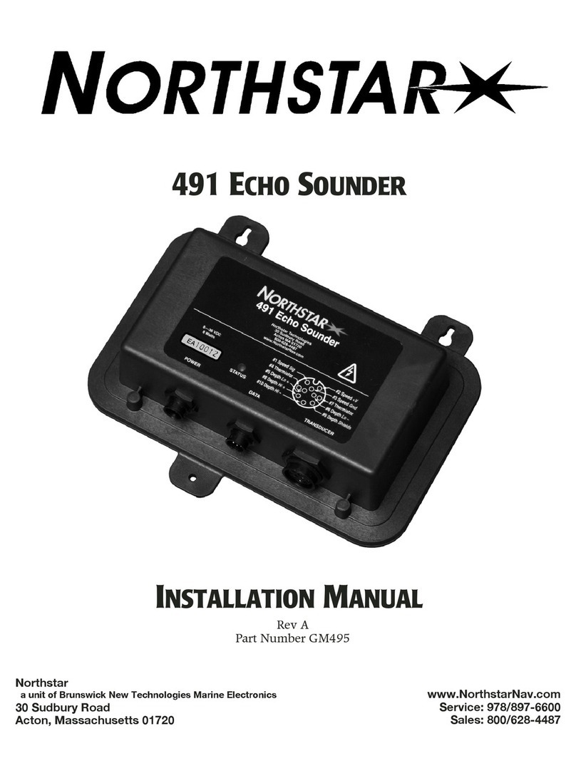
NorthStar 8000I 1KW NETWORK SOUNDER User manual

Northstar 8000i
1 kW Network Sounder
Installation Manual
www.northstarnav.com

2Northstar 8000i 1 kW Network Sounder Installation Manual
1Warning and safety information
IMPORTANT SAFETY INFORMATION
Please read carefully before use
This is the safety alert symbol. It is used to alert you to
potential personal injury hazards. Obey all safety
measures that follow this symbol to avoid possible
injury or death.
WARNING indicates a potentially hazardous situation
which, if not avoided, could result in death or serious
injury.
CAUTION indicates a potentially hazardous situation
which, if not avoided, may result in minor or
moderate injury.
CAUTION used without the safety alert symbol
indicates a potentially hazardous situation which, if
not avoided, may result in property damage.
Read and observe the Warnings and Notices in the
Northstar 8000i System Installation Manual.

Contents
1Warning and safety information 2
2Disclaimer 4
3Warranty 4
4Northstar 8000i 600 W/
1 kW Network Sounder 5
5What comes with your Northstar
8000i 600 W/1 kW Network Sounder 7
6Network Sounder Installation 9
7Transducer Selection and Installation 13
8Maintenance 21
9Specifications 21
10 Technical support, service and repairs 22

4 Northstar 8000i 1 kW Network Sounder Installation Manual
2Disclaimer
As Northstar is continuously improving this product we retain the right to make
changes to the product at any time which may not be reflected in this version of the
manual. Please contact your nearest Northstar distributor if you require any further
assistance.
It is the owner’s sole responsibility to install and use the instrument and transducers
in a manner that will not cause accidents, personal injury or property damage. The
user of this product is solely responsible for observing safe boating practices.
BRUNSWICK NEW TECHNOLOGIES INC. AND ITS SUBSIDIARIES AND AFFILIATES
DISCLAIM ALL LIABILITY FOR ANY USE OF THIS PRODUCT IN A WAY THAT MAY CAUSE
ACCIDENTS, DAMAGE OR THAT MAY VIOLATE THE LAW.
Governing Language: This statement, any instruction manuals, user guides and other
information relating to the product (Documentation) may be translated to, or has
been translated from, another language (Translation). In the event of any conflict
between any Translation of the Documentation, the English language version of the
Documentation will be the official version of the Documentation.
This manual represents the product as at the time of printing. Brunswick New
Technologies Inc. and its subsidiaries and affiliates reserve the right to make changes
to specifications without notice.
Copyright © 2006 Brunswick New Technologies Inc. Northstar™ is a registered
trademark of Brunswick New Technologies Inc.
3Warranty
The Northstar Warranty Statement is supplied as a separate document.
It is shipped with the Product Registration Card.
In case of any queries, refer to www.northstarnav.com.

Northstar 8000i 1 kW Network Sounder Installation Manual 5
4Northstar 8000i 600 W/1 kW
Network Sounder
This manual describes how to install the unit, and must be used with the guides in
the Northstar 8000i System Processor Installation Manual and also with the
transducer installation manual.
The Northstar 8000i 1 kW / 600 W Network Sounder can connect to these optional
sensors:
a variety of Airmar / Radarsonics depth transducer to measure depth
and details in the water under the boat (see "Transducer Selection and
Installation" page 13)
petrol/gasoline fuel flow sensors (FUTURE)
NMEA, NavBus (FUTURE)
600 W/1 kW Network Sounder - Front view
A Power Connector Connect to ships Power supply
B Network Connector Connect to the Northstar 8000i Network see network
section under wiring guidelines in the 8000i system
processor installation guide
C Options Cable
Connector
Connect to external devices (FOR FUTURE USE)
D Fuel Transducer
connector
Connect to Northstar Diesel or Gasoline Fuel
transducers (FOR FUTURE USE)
E Sonar Transducer
connector
Connect Transducer (Purchase Separately)

6 Northstar 8000i 1 kW Network Sounder Installation Manual
600 W/1 kW Network Sounder - Top view
A POWER LED Red LED indicates when power is powered on
B NETWORK LED Green LED indicates that the network connection is
active
C DEPTH TDXR LED Green LED Indicates that the transducer is connected
and operating
D Panel Mounting
Holes
Provides a way of mounting the unit to a bulkhead

Northstar 8000i 1 kW Network Sounder Installation Manual 7
5What comes with your Northstar 8000i
600 W/1 kW Network Sounder
600 W/1 kW Network Sounder NS004741
Small Protective Caps x 2 MS000333-G Power Cable NS004800
Mounting Screws x 6 HR000087
This Manual MN000614D-G Warranty

8 Northstar 8000i 1 kW Network Sounder Installation Manual
Registration Card Mounting Template LA000591A-G
Also required:
Depth Transducer, supplied separately, use either of the following transducers
Make and Model Power Frequency Northstar P/N
Airmar B260 Bronze
Through Hull
1 kW 50 kHz / 200 kHz NS002660R
Airmar B258 Bronze
Through Hull
1 kW 50 kHz / 200 kHz AA002020
Airmar TM258 Plastic
Transom mount
1 KW 50 kHz / 200 kHz NS002658R
Airmar P319 Compact
plastic thru hull
600 W 50 kHz / 200 kHz AA002107R
Radarsonics, 210B thru
hull
600 W 50 kHz / 200 kHz AA002108R
Radarsonics 250
Transom mount
tri function
600 W 50 kHz / 200 kHz AA002077R
A network cable to connect to Northstar 8000i network. Choose from the following
cable lengths
NS004810 Network Cable 1.6 ft (0.5 m)
NS004811 Network Cable 6.5 (2 m)
NS004812 Network Cable 16.5 ft (5 m)
NS004813 Network Cable 33 ft (10 m)
NS04814 0 Northstar 8000i Cable - Ethernet Joiner, male to male
NS004815 Northstar 8000i Cable - Cross Over Joiner.

Northstar 8000i 1 kW Network Sounder Installation Manual 9
6Network Sounder Installation
Read and observe the Warnings and Notices in the
8000i System Processor Installation Manual.
Follow the 8000i system installation guide in the 8000i System Processor Installation
Manual.
Find a suitable location for the unit following the Location Guidelines in the 8000i
system Processor Installation Manual.
Find a suitable location for the unit.
The unit is best mounted onto a vertical panel with the connectors facing down and
any cables made with drip loops. The unit and all connectors are waterproof. The unit
screws to a vertical panel with the connectors facing down.
Use the screws supplied to secure the enclosure to the panel.

10 Northstar 8000i 1 kW Network Sounder Installation Manual
Connecting the sounder
A Northstar 8000i 1 kW / 600 W Network Sounder NS004741
B Northstar 8000i 8 Port Network Linker NS004721
C Transducer
D Network Cable
E DC power : Use a 5 Amp fuse

Northstar 8000i 1 kW Network Sounder Installation Manual 11
Connect Power
Connect to power source using the supplied power cable making sure a 5 Amp fuse is
used
A Red Battery Positive
B Black Battery Negative
C Brown Ships Ground
D Fuse Use a 5 Amp fuse or breaker
Battery 12 V DC or 24 V DC Nominal
Connect to the 8000i network
Connect the Sounder processor to the 8000i network by using one of the following
8000i network cables, connect one end to the sounders network port and the other
to the 8000i Network linker.
Network Cable 1.6 ft (0.5 m) NS004810
Network Cable 6.5 ft (2 m) NS004811
Network Cable 16.5 ft (5 m) NS004812
Network Cable 33 ft (10 m) NS004813
NS004817 Unterminated Cable 328 ft (100 m) (Use NS4816
Network Connector Field Terminating Kit)
If the sounder is part of network that has only two (2) network devices use a crossover
cable as below
Crossover Cable NS004815

12 Northstar 8000i 1 kW Network Sounder Installation Manual
Options Port (FUTURE)
Options Cable NS004801
1 Purple RS-422 out +
2 Pink RS-422 out -
3 Yellow NMEA out +
4 Black Ground (NMEA output -)
5 Black/White RS422 -
6 White RS422 +
7 Orange NavBus +
8 Blue NavBus -
9 Dark Green External alarm
10 Brown/White Remote power on (Inverted)
11 Gray N/C
12 Light Green Remote power on
Fuel Port (Future)
Fuel Port Connector (Future)
1 Ground
2 +9 V Fuel
3
4 Fuel B Input Single/ Port
5
6 Fuel A Input Twin/ Starboard
7 NavBus Fuel
8

Northstar 8000i 1 kW Network Sounder Installation Manual 13
7Transducer Selection and Installation
Be sure to turn the power off before starting the installation. Further, it is highly
recommended that you keep power off while you’re performing the installation. If
power is left on or turned on during the installation, fire, electrical shock, or other
serious injury may occur. Be sure to ground the equipment to prevent electrical shock
and mutual interference. Be sure the transducer outputs are tied together before
handling to avoid electrical charge build-up.
Be sure to use a 5 Amp fuse. Using the incorrect fuse can result in fire or damage to
the Network Sounder
Mounting the transducer requires drilling holes through the hull; make sure the
installation does not cause the vessel to leak.
A thru-hull installation should be performed by a professional installer. Do not
attempt this unless you are fully qualified. Do not perform a thru-hull installation of
the transducer when the vessel is actually in the water.
Immediately after installing the transducer, be sure to check for leaks, and don’t
leave the vessel in the water for more than three hours before checking it again.
Northstar assumes no responsibility for improper or incorrect installation of a
transducer.
The following basic setup information is not a substitute for the installation
instructions provided by the transducer’s manufacturer. To ensure that you meet all
critical installation parameters, be sure to read and follow all of the requirements in
their instructions. Northstar assumes no responsibility for improper installation.

14 Northstar 8000i 1 kW Network Sounder Installation Manual
Selecting a transducer
Make and Model Power Frequency Northstar P/N
Airmar B260 Bronze
Through Hull
1 kW 50 kHz / 200 kHz NS002660R
Airmar B258 Bronze
Through Hull
1 kW 50 kHz / 200 kHz AA002020
Airmar TM258 Plastic
Transom mount
1 KW 50 kHz / 200 kHz NS002658R
Airmar P319 Compact
plastic thru hull
600 W 50 kHz / 200 kHz AA002107R
Radarsonics, 210B thru
hull
600 W 50 kHz / 200 kHz AA002108R
Radarsonics 250
Transom mount tri
function
600 W 50 kHz / 200 kHz AA002077R
AIRMAR B260 NS002660R
Application
Sport fishing boats above 26 ft (8 m)
•small to midsize commercial fishing boats
Includes high performance fairing reduces drag and directs smooth water over the
transducer’s face for excellent echo sounder performance at all speeds
•includes temperature sensor
•robust bronze housing and nut.
Frequencies Beam
With
(@-3dB)
Rated RMS
Power: (W)
Figure of
Merit
Q Depth range
50 kHz-AE 19° 1 kW -14 8 1800 ft –
2500 ft
529 m –
735 m
200 kHz AWlg 6° 1 kW -15 10 700 ft –
1000 ft
206 m –
294 m
Acoustic Window Urathane
Weight 16 lb (7.3 kg)
Hull Dead rise
Angle
Up to 28 Degrees with fairing block
Hole Diameter 1 inch (26 mm)

Northstar 8000i 1 kW Network Sounder Installation Manual 15
AIRMAR B258 AA002020
Included high performance fairing reduces drag and directs smooth water over the
transducer’s face for excellent echo sounder performance at all speeds
•includes temperature sensor
•robust bronze housing and nut
Frequencies Beam
With
(@-3dB)
Rated RMS
Power: (W)
Figure of
Merit
Q Depth range
50 kHz-AE 15°x21° 1 kW -17 9 1500 ft –
2200 ft
441 m –
647 m
200 kHz AWlg 3°x5° 1 kW -9 15 700 ft –
1000 ft
206 m –
294 m
Acoustic Window Urathane
Weight 7.9 lb (3.6 kg)
Hull Dead rise Angle Up to 25 Degrees with fairing block
Hole Diameter 1 inch (26 mm)

16 Northstar 8000i 1 kW Network Sounder Installation Manual
AIRMAR TM 258 NS002658R
Applications
•single or multiple outboard boats
•center console boats
•small trailer boats
•bass boats
Frequencies Beam
With
(@-3dB)
Rated RMS
Power: (W)
Figure of
Merit
Q Depth range
50 kHz-AE 15° x 21° 1 kW -17 9 1500 ft –
2200 ft
441 m –
647 m
200 kHz AWlg 3° x 5° 1 kW -9 15 700 ft –
1000 ft
206 m –
294 m
Acoustic Window Urathane
Weight 7.9 lb (3.6 kg)
Hull Dead rise Angle Up to 25 Degrees with fairing block
Hole Diameter 1 inch (26 mm)

Northstar 8000i 1 kW Network Sounder Installation Manual 17
Airmar P319 AA002107R
Frequencies Beam
With
(@-3dB)
Rated RMS
Power: (W)
Figure of
Merit
Q Depth range
50 kHz-AE 45° 600 W -31 28 800 ft –
1200 ft
235 m –
353 m
200 kHz AWlg 12° 600 W -21 31 700 ft –
1000 ft
118 m –
206m
Acoustic Window Urathane
Weight 7.9 lb (3.6 kg)
Hull Dead rise Angle 0°-12° optimum 20° Maximum
Hole Diameter 2 inch (51 mm)

18 Northstar 8000i 1 kW Network Sounder Installation Manual
Radarsonics 210B AA002108
Frequencies Beam With (@-3dB) Rated RMS Power: (W)
50 kHz-AE 45 600 W
200 kHz AWlg 11 600 W
Acoustic Window Urathane
Weight 3.1 lbs (1.4 kg)
Hole Diameter 2.25" (57.1 mm)

Northstar 8000i 1 kW Network Sounder Installation Manual 19
The following basic setup information is not a substitute for the installation instructions
provided by the transducer’s manufacturer. To ensure that you meet all critical installation
parameters, be sure to read and follow all of the requirements in their instructions.
Northstar assumes no responsibility for improper installation.
Selecting the best location for the transducer
The two most common problems with echo sounder installations stem from electrical
noise and cavitation. Either of these situations can produce poor performance.
Electrical noise occurs when the transducer cable is routed too closely to noise-
producing electronics, such as alternators, AC generators, radars, etc. To avoid
problems with noise, route the transducer cable by itself (not in a bundle) and away
from other wires or cables and the engine.
Cavitation can occur at high speeds. During cavitation, bubbles form between the
transducer and the water. When this happens, the transducer can’t get its energy into
the water properly and won’t be able to detect any echoes. To avoid cavitation,
choose a mounting location with good water flow all around it at all speeds.
Before any drilling or cutting takes place, carefully choose a mounting location for the
transducer that meets the following criteria, depending on the type of vessel:
the transducer is more than four feet away from the Northstar
navigator and other similar equipment, to prevent mutual electrical
and magnetic interference
the transducer and its cable are as far as possible from other electrical
cables
there is space above the transducer for the transducer’s stem,
housing, and cable
the path for running the transducer’s cable is reasonably direct—keep
in mind that the transducer cable is 33 feet long (10 meters). To
prevent damage, coil any excess cable and secure it
water turbulence and noise are minimal, decreasing the amount of
bubbles passing over the transducer face
the transducer isn’t behind hull irregularities or near eroding paint;
both indicate areas subject to turbulence
the transducer is as far as possible from the engine or propellers, and
inboard of the lifting strakes
the transducer always remains submerged and parallel to the water
surface
the transducer is easily accessible from inside the vessel for
adjustments and maintenance

20 Northstar 8000i 1 kW Network Sounder Installation Manual
the transducer’s ultrasonic beams aren’t obstructed by the keel,
propeller shafts, or any other part of the vessel the hull thickness falls
within the limits in Table 3 below (all dimensions are perpendicular to
the waterline):
Best Location for the Transducer
Displacement hull. A - Pressure waves
Planing hull - Outboard and I/O Planing hull - Inboard
Stepped hull Fin keel sailboat
Full keel sailboat
A flat-bottom hull provides the best environment for mounting the transducer:
It provides a horizontal surface and a constant water flow over the transducer, with
little turbulence (see Figure 2 for the recommended transducer incline angle). If the
vessel has a deadrise angle greater than 5 degrees, mount the transducer on a fairing
This manual suits for next models
1
Table of contents
Other NorthStar Marine Equipment manuals