SICK VISIC50SF User manual

MMM
I
MMMOPERATING INSTRUCTIONS
OPERATING INSTRUCTIONS
VISIC50SF
Smoke Detector in Tunnels
Title Page

28016984/1DPO/V2-0/2023-07| SICKOPERATING INSTRUCTIONS |VISIC50SF
Subject to change without notice
Described product
Product name: VISIC50SF
Manufacturer
SICK AG
Erwin-Sick-Str. 1
D-79183 Waldkirch
Germany
Legal information
This work is protected by copyright. All rights derived from the copyright shall be reserved
for SICK AG. Reproduction of this document or parts of this document is only permissible
within the limits of the legal determination of Copyright Law. Any modification,
shortening or translation of this document is prohibited without the express written
permission of SICK AG.
The trademarks stated in this document are the property of their respective owner.
© SICK AG. All rights reserved.
Original document
This document is an original document of SICK AG.
3
8016984/1DPO/V2-0/2023-07| SICK OPERATING INSTRUCTIONS |VISIC50SF
Subject to change without notice
Symbols and document conventions
Warning symbols
Warning levels and signal words
DANGER
Risk or hazardous situation which will result in severe personal injury or death.
WARNING
Risk or hazardous situation which could result in severe personal injury or death.
CAUTION
Risk with the possible consequence of minor or slight injuries.
NOTICE
Hazard which could result in property damage.
Information symbols
Data integrity
SICK AG uses standardized data interfaces, such as standard IP technology, in its
products. The focus here is on the availability of the products and their properties.
SICK AG always assumes the integrity and confidentiality of data and rights affected in
connection with the use of the products are ensured by the customer.
In all cases, the customer is responsible for the implementation of safety measures
suitable for the respective situation, e.g., network separation, firewalls, virus protection
and patch management.
Hazard (general)
Hazard by voltage
Hazard for the environment/nature/organic
life
Important technical information for this product
Important information on electric or electronic functions
Supplementary information
Link to information at another place

CONTENTS
48016984/1DPO/V2-0/2023-07| SICKO P E R A T I N G I N S T R U C T I O N S | VISIC50SF
Subject to change without notice
1 Important information .............................................................................. 9
1.1 About this document ...................................................................................... 9
1.2 Responsibility of user ..................................................................................... 9
1.3 Intended use................................................................................................. 10
1.3.1 Purpose of the device .................................................................. 10
1.3.2 Product identification .................................................................. 10
1.3.3 Mounting location ........................................................................ 10
2 Product description ................................................................................. 11
2.1 Features of the VISIC50SF ........................................................................... 11
2.2 Device versions............................................................................................. 12
2.2.1 Standard components: VISIC50SF visibility measurement
(K-value)........................................................................................ 12
2.2.2 Optional equipment...................................................................... 12
2.2.3 Measuring principle...................................................................... 16
2.2.4 Interior view of the VISIC50SF ..................................................... 16
2.3 Interfaces ...................................................................................................... 19
2.3.1 Analog interfaces characteristics ................................................ 19
2.3.2 Digital interfaces properties ........................................................ 19
2.3.3 Modbus-RTU interface characteristics ........................................ 19
3 Mounting and electrical installation ..................................................... 20
3.1 Safety information ........................................................................................ 20
3.2 Material required .......................................................................................... 21
3.3 Preparing the mounting location ................................................................. 22
3.4 Mounting ....................................................................................................... 22
3.4.1 Scope of delivery .......................................................................... 22
3.4.2 Mounting the VISIC50SF.............................................................. 22
3.4.3 Mounting the connection unit (optional)..................................... 26
3.4.4 Mounting the TAD control unit (optional) .................................... 27
3.4.5 Mounting of temperature sensor PT1000 (optional).................. 27
3.5 Wiring of VISIC50SF...................................................................................... 29
3.5.1 Safety information ....................................................................... 29
3.5.2 Connecting the LED...................................................................... 29
3.5.3 Wiring of analog outputs, relay outputs and voltage supply ...... 31
3.5.4 Bus interface wiring ..................................................................... 32
3.5.5 Shielding ....................................................................................... 32
3.5.6 Connection unit wiring ................................................................. 34
3.5.7 TAD control unit wiring ................................................................. 35
3.6 Connections .................................................................................................. 36
3.6.1 Standard version .......................................................................... 36
3.6.2 VISIC50SF with connection unit .................................................. 36
3.6.3 VISIC50SF with TAD control unit.................................................. 37
Contents

CONTENTS
5
8016984/1DPO/V2-0/2023-07| SICK O P E R A T I N G I N S T R U C T I O N S | VISIC50SF
Subject to change without notice
4 Commissioning ........................................................................................38
4.1 Commissioning, step by step........................................................................38
4.2 Bus connections............................................................................................40
4.3 Modbus-RTU (integrated in the VISIC50SF standard version) ....................40
4.3.1 Modbus-RTU data format .............................................................40
4.3.2 Modbus-RTU baud rates...............................................................40
4.3.3 Read Holding Register..................................................................41
4.3.4 Modbus-RTU Read Coil (0x01) .....................................................42
4.4 PROFIBUS DP-V0 (optional) ..........................................................................42
4.4.1 PROFIBUS addressing ..................................................................42
4.4.2 PROFIBUS DP-V0 baud rates........................................................43
4.4.3 Access via GSD file for configuration 1 .......................................43
4.4.4 Access via GSD file for configuration 2 .......................................44
4.4.5 Measured value coding ................................................................46
4.5 RS-485 - topology and bus termination .......................................................47
4.6 Stub line lengths for connection unit on all RS-485 bus systems ..............48
5 Operation ..................................................................................................49
5.1 Operating and display elements...................................................................49
5.1.1 Display with keypad in VISIC50SF................................................49
5.1.2 Reset button and “Maint” LED.....................................................49
5.1.3 Display unit in the TAD control unit .............................................49
5.2 Operating states............................................................................................50
5.2.1 Checking the operating state (visual control)..............................50
5.2.2 Checking malfunction displays ....................................................50
5.3 Checking the analog outputs........................................................................50
5.3.1 Reading off measured values ......................................................50
5.4 Operating functions.......................................................................................51
5.5 Status messages...........................................................................................51
5.5.1 Malfunction messages .................................................................51
5.5.2 Maintenance request messages,.................................................51
6 Menu navigation VISIC50SF...................................................................52
6.1 Menu structure..............................................................................................52
6.1.1 Short description: Settings using the keypad..............................52
6.1.2 Input field with a blinking digit to be edited ................................52
6.2 Measuring operation mode “RUN” ...............................................................52
6.3 “SET” mode ...................................................................................................53
6.3.1 Navigation in “SET” mode ............................................................53
6.3.2 Structure and sequence of submenu items ................................53
6.3.3 Activating maintenance in menu item “Maint” ...........................54
6.3.4 Calling up maintenance request and malfunction messages
with menu item “Status” ..............................................................54
6.3.5 Calling-up the operating duration in submenu item “Uptime” ...55
6.3.6 Calling up the software version in submenu item “SwVers”.......55

CONTENTS
68016984/1DPO/V2-0/2023-07| SICKO P E R A T I N G I N S T R U C T I O N S | VISIC50SF
Subject to change without notice
6.4 Connecting the bus systems ........................................................................ 56
6.4.1 Setting the RS-485 interface with submenu item “Bus”............ 56
6.5 Setting bus parameters................................................................................ 57
6.5.1 Setting the PROFIBUS address in “PB ID”................................... 57
6.5.2 Setting the PROFIBUS configuration under “PBCONF”............... 57
6.5.3 Setting the Modbus address in “MB ID” ..................................... 58
6.5.4 Setting the Modbus data transfer format with menu item
“MB Par” ....................................................................................... 58
6.5.5 Setting the Modbus baud rate with menu item “MB BdR”......... 59
6.6 Testing digital/analog outputs ..................................................................... 60
6.6.1 Signal test “IO test”...................................................................... 60
6.6.2 Testing the analog output for the K-value with menu item “k”.. 60
6.6.3 Testing the analog output for the temperature value with
menu item “Temp” ....................................................................... 61
6.6.4 Testing the “Maintenance request” relay with menu item
“MRq” ........................................................................................... 61
6.6.5 Testing the malfunction relay with menu item “Fail” ................. 61
6.6.6 Testing the limit value relay with menu item “Limit”.................. 62
6.7 Upper limit for scaling of analog output with menu item “AO HI” ............. 62
6.8 Setting limit values in the “Limit” menu item.............................................. 63
6.8.1 Setting the limit value for the visibility value (K-value) using
menu item “K”.............................................................................. 63
6.8.2 Setting the limit value for rate of increase of K-value with
menu item “K_G” ......................................................................... 63
6.8.3 Setting the limit value for the temperature value with menu
item “Temp”.................................................................................. 64
6.8.4 Setting the limit value for the gradient value of the
temperature using menu item “Gradient Temp” ........................ 64
6.8.5 Setting the limit value for contamination with menu item
“Contam” ...................................................................................... 64
6.9 Setting limit values in menu item “PreLim” (optional)................................ 65
6.9.1 Setting the limit value for the visibility value (K-value) using
menu item “K”.............................................................................. 65
6.9.2 Setting the limit value for rate of increase of K-value with
menu item “K_G” ......................................................................... 65
6.9.3 Setting the limit value for the temperature value with menu
item “Temp”.................................................................................. 66
6.9.4 Setting the limit value for the gradient value of the
temperature using menu item “Temp_G” ................................... 66
6.9.5 Setting the pre-alarm value for contamination with menu
item “Contam” .............................................................................. 66
6.10 Device adjustment with submenu item “Tuning”........................................ 67
6.11 Setting digital outputs with “DOMode” (optional) ....................................... 67
6.12 Activating/deactivating the heating (optional)............................................ 68

CONTENTS
7
8016984/1DPO/V2-0/2023-07| SICK O P E R A T I N G I N S T R U C T I O N S | VISIC50SF
Subject to change without notice
7 Menu navigation TAD control unit.........................................................69
7.1 Basic features ...............................................................................................69
7.2 Main functions ..............................................................................................69
7.3 Switch-on procedure .....................................................................................69
7.4 Operating elements.......................................................................................70
7.4.1 LEDs ..............................................................................................70
7.4.2 Function buttons...........................................................................71
7.5 Starting operation .........................................................................................72
7.5.1 Initialization phase .......................................................................72
7.5.2 Measuring screens: List and bar display .....................................73
7.5.3 Displaying the Main menu............................................................74
7.5.4 Selecting the menu item ..............................................................74
7.5.5 Returning to the measuring screen .............................................74
7.5.6 Selecting the menu language ......................................................74
7.5.7 Setting the display contrast .........................................................75
7.5.8 Changing numerical parameters..................................................75
7.6 Activating Maintenance mode......................................................................76
7.7 Main menu item “Diagnosis”........................................................................76
7.7.1 Calling up the operation duration: “Uptime” ...............................77
7.7.2 Retrieving device information with “Device Info”........................77
7.7.3 Retrieving the state of peripheral equipment with submenu
item “Peripheral” ..........................................................................78
7.7.4 Displaying messages with menu item “Messages”.....................78
7.8 Testing digital/analog outputs .....................................................................80
7.8.1 Testing the analog output for the K-value ...................................80
7.8.2 Testing the analog outputs for temperature ...............................80
7.8.3 Testing the “Fault” relay with submenu item “Fault”..................81
7.8.4 Testing the “Maintenance Request” relay with submenu item
“Maintenance Req.” .....................................................................81
7.8.5 Testing the relay “Limit value” .....................................................81
7.9 Performing settings on the device with menu item “Configuration” ..........82
7.9.1 Scaling analog outputs with menu item “Scale AO” ...................82
7.9.2 Setting the PROFIBUS address in “PROFIBUS ID”.......................83
7.9.3 Setting limit values in the “Limit” menu item..............................83
8 Shutdown ..................................................................................................86
8.1 Technical knowledge necessary for shutdown ............................................86
8.2 Safety information on shutting down ...........................................................86
8.3 Preparations for shutdown ...........................................................................86
8.4 Switch-off procedure .....................................................................................86
8.5 Protective measures for shutdown device...................................................86
8.5.1 Measures for short-term shutdown .............................................86
8.6 Transport .......................................................................................................87
8.7 Disposal.........................................................................................................87

CONTENTS
88016984/1DPO/V2-0/2023-07| SICKO P E R A T I N G I N S T R U C T I O N S | VISIC50SF
Subject to change without notice
9 Maintenance............................................................................................. 88
9.1 Necessary technical knowledge for maintenance work ............................. 88
9.2 Safety instructions for maintenance work .................................................. 88
9.3 Maintenance ................................................................................................. 88
9.3.1 VISIC50SF maintenance .............................................................. 88
9.3.2 Maintenance plan ........................................................................ 93
9.3.3 Tunnel cleaning ............................................................................ 93
9.4 When requesting Customer Service from SICK........................................... 93
9.5 Spare parts .................................................................................................. 94
9.5.1 Spare parts for VISIC50SF ........................................................... 94
9.5.2 Spare parts for connection unit................................................... 94
9.5.3 Spare parts for TAD control unit ................................................. 94
10 Clearing malfunctions............................................................................. 95
10.1 Description of device errors ......................................................................... 95
10.2 Description of maintenance requests ......................................................... 96
10.3 Display of error states on the control unit................................................... 96
10.4 Further error causes..................................................................................... 96
11 Specifications........................................................................................... 97
11.1 Compliances ................................................................................................. 97
11.1.1 Electrical protection ..................................................................... 97
11.1.2 Standards observed ..................................................................... 97
11.1.3 Declaration of Conformity ............................................................ 97
11.2 Dimensions ................................................................................................... 98
11.2.1 Dimension drawing VISIC50SF .................................................... 98
11.2.2 Dimension drawing, connection unit ........................................... 99
11.2.3 Dimension drawing TAD control unit .........................................100
11.2.4 Dimension drawing VISIC50SF ceiling mounting, not swivel-
mounted .....................................................................................101
11.2.5 Dimension drawing VISIC50SF ceiling mounting, swivel-
mounted .....................................................................................101
11.2.6 Drilling plan VISIC50SF ..............................................................102
11.2.7 Drilling plan connection unit......................................................103
11.2.8 Drilling plan TAD control unit .....................................................104
11.2.9 Drilling plan mounting plate for ceiling mounting.....................105
11.3 Technical data ............................................................................................106

9
8016984/1DPO/V2-0/2023-07| SICK O P E R A T I N G I N S T R U C T I O N S | VISIC50SF
Subject to change without notice
IMPORTANT INFORMATION 1
1 Important information
1.1 About this document
●This Manual describes:
– Device components
–Installation
–Operation
– Maintenance work required
●It contains important safety information for safe operation.
1.2 Responsibility of user
▸Read the Operating Instructions before putting the VISIC50SF into operation.
▸Observe all safety information.
▸If anything is not clear: Please contact SICK Customer Service.
Designated users
The VISIC50SF may be operated by competent persons only who, based on their device-
specific training and knowledge of the device as well as knowledge of the relevant
regulations, can assess the tasks given and recognize the hazards involved.
Correct use
●This Manual presumes that the VISIC50SF has been delivered as specified during
project planning and with the relevant delivery state of the VISIC50SF (→delivered
system documentation).
●If you are not sure whether the VISIC50SF complies with the planned configuration or
the delivered System Documentation:
▸Please contact SICK Customer Service.
●The VISIC50SF should only be used as described in these Operating Instructions, see
“Purpose of the device”, page 10. The manufacturer assumes no responsibility for any
other use.
●Maintenance work should be performed as prescribed in this Manual.
●Do not attempt any work on or repairs to the VISIC50SF unless described in this Manual.
●Do not modify the VISIC50SF in any way unless specifically instructed and permitted to
do so by the manufacturer.
●Use only original spare parts and wear and tear parts from SICK.
If not observed:
●Any warranty of the manufacturer is void.
●The VISIC50SF can become dangerous.
Special local conditions
▸Follow all local laws, regulations, and company policies applicable at the mounting
location.
Retention of document
These Operating Instructions:
●Must be available for reference.
●Must be conveyed to new owners.

10 8016984/1DPO/V2-0/2023-07| SICKO P E R A T I N G I N S T R U C T I O N S | VISIC50SF
Subject to change without notice
1IMPORTANT INFORMATION
1.3 Intended use
1.3.1 Purpose of the device
The VISIC50SF is designed for quick and secure detection of smoke in tunnels.
1.3.2 Product identification
The type plate is located on the side on the rear enclosure panel.
1.3.3 Mounting location
●In the tunnel for smoke detection
●On tunnel portals
●In basement garages
●Generally for smoke detection in applications similar to tunnels
Product name: VISIC50SF
Manufacturer: SICK AG
Erwin-Sick-Str. 1 · 79183 Waldkirch · Germany
11
8016984/1DPO/V2-0/2023-07| SICK O P E R A T I N G I N S T R U C T I O N S | VISIC50SF
Subject to change without notice
PRODUCT DESCRIPTION 2
2 Product description
2.1 Features of the VISIC50SF
▸Simultaneous or individual measurement of
a) Standard:
– Visibility (K-value) for smoke detection
b) Optional
– Temperature of ambient air
▸Measuring visibility with fog dissipation (optional).
▸Compact design with low space requirements.
▸Already calibrated ex factory, no readjustment required onsite (Plug & Measure).
▸Scope of delivery with or without connection unit.
▸Scope of delivery with or without TAD control unit.
▸Keypad and single-line display in the measuring unit to
– Display values when the device is open.
– Control diagnosis and maintenance.
– Assign device addresses when using bus wiring.
– Configure alarm thresholds.
▸Status LED signals error-free operation (green), maintenance request (yellow) and
malfunction (red).
▸Standard: 2 analog outputs and 3 igital outputs, 1 x Modbus-RTU.
▸Optional: PROFIBUS DP-V0.
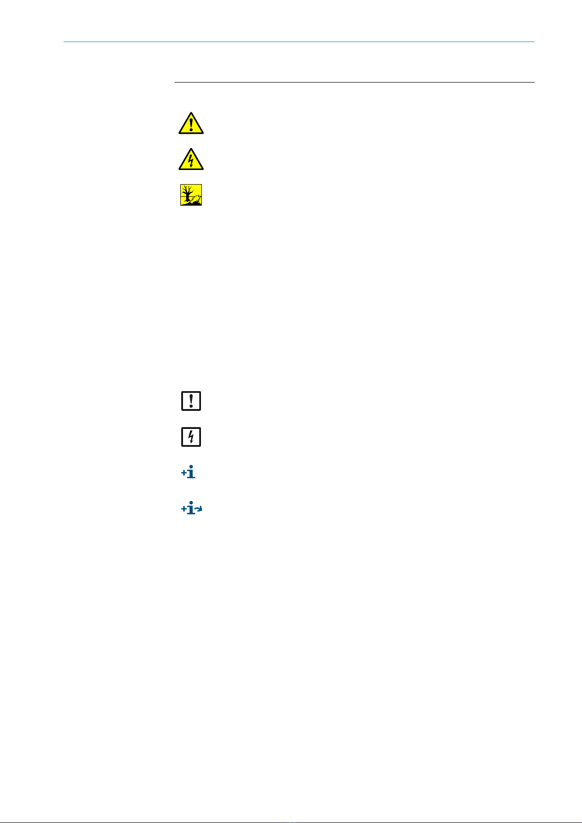
Fig. 1: Application example VISIC50SF
ca. 150 m
...
ca.150 m
ʛʛ
ʛ
ʛ
ʛ
ʛ
K-value
Option:
- Connection unit and/or control unit TAD
- Fog dissipation: Version with heating
Tunnel
control
room

12 8016984/1DPO/V2-0/2023-07| SICKO P E R A T I N G I N S T R U C T I O N S | VISIC50SF
Subject to change without notice
2PRODUCT DESCRIPTION
2.2 Device versions
2.2.1 Standard components: VISIC50SF visibility measurement (K-value)
Fig. 2: VISIC50SF sensor
2.2.2 Optional equipment
2.2.2.1 Temperature measurement PT1000
Fig. 3: Temperature sensor PT1000
4
5
6
2
7
2
1
3
Enclosure cover
Inlet opening for air to be measured
Rear enclosure panel with mounting bracket
Status LED
Screw plugs
Electrical screw fitting for line (10 ... 14 mm)
Electrical screw fitting for line (6 ... 12 mm)
Connection for functional grounding
8
1
2
Temperature sensor
Plug connections
13
8016984/1DPO/V2-0/2023-07| SICK O P E R A T I N G I N S T R U C T I O N S | VISIC50SF
Subject to change without notice
PRODUCT DESCRIPTION 2
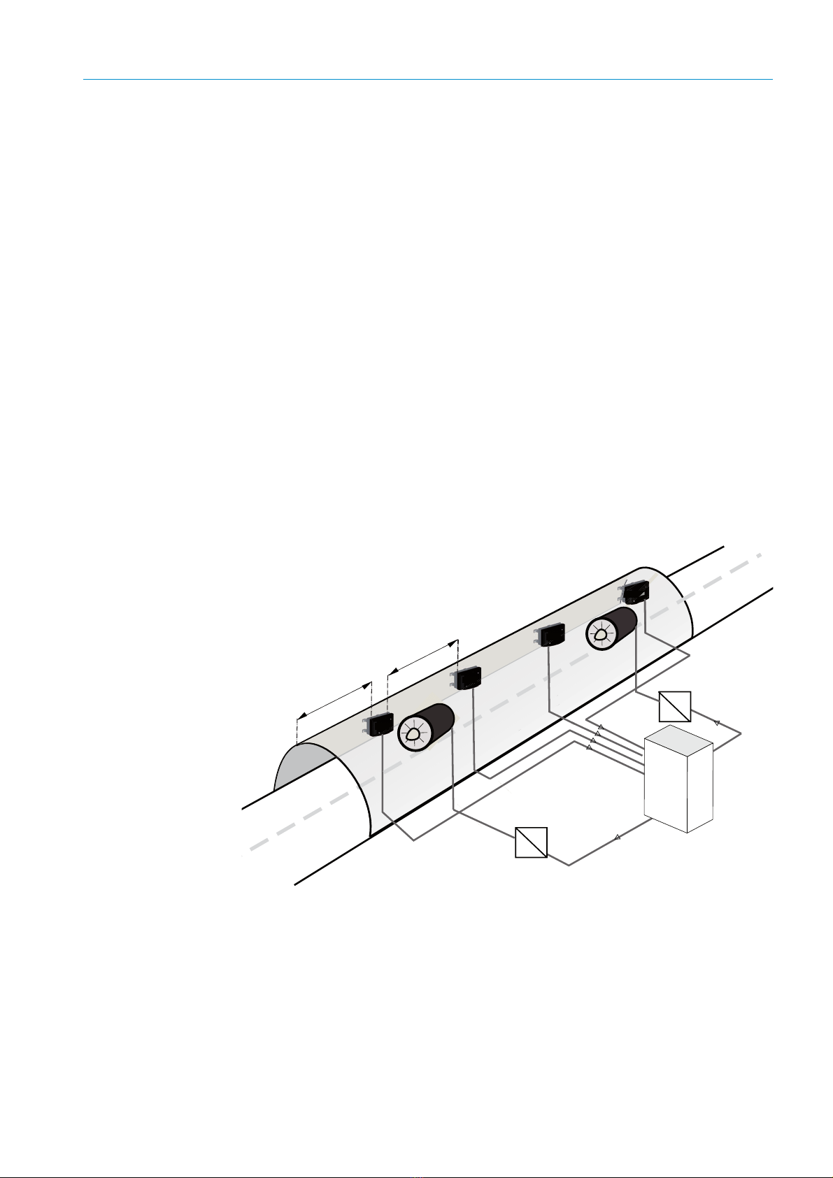
2.2.2.2 Connection unit
2 variants:
●TB-A1: Connection unit for reconnection of cables. It contains:
– 10 terminals to connect cables provided by the customer.
●TB-A2: Connection unit to connect the VISIC50SF to the power voltage. It contains:
– Power supply filter, terminals and a power supply unit.
Fig. 4: Connection unit with 24 V power supply for the sensor
Specifications concerning stub lines see “Stub line lengths for connection unit on all RS-
485 bus systems”, page 48 must always be adhered to when the VISIC50SF and the
associated connection unit are part of a bus system.
Enclosure cover
Rear enclosure panel with mounting bracket
Electrical screw fittings for cables:
●3 x 6 ... 11 mm
●2 x 10 ... 14 mm
Grounding
1
2
4
3
Ready-made connection cables are available for both variants. (Further details on
connection cables, see “Installation material”, page 21)
14 8016984/1DPO/V2-0/2023-07| SICKO P E R A T I N G I N S T R U C T I O N S | VISIC50SF
Subject to change without notice
2PRODUCT DESCRIPTION
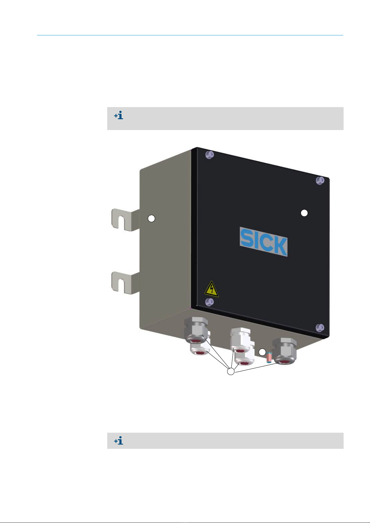
2.2.2.3 Control unit TAD
2 variants:
●TAD100 standard control unit
●TAD100 control unit with optional I/Os
Fig. 5: TAD control unit
1
2
Enclosure cover
Display unit
Screw fittings for the cables
– 4 x 6 ... 12 mm (M20 x 1.5)
– 1 x 5 ... 10 mm (M16 x 1.5)
4
3
15
8016984/1DPO/V2-0/2023-07| SICK O P E R A T I N G I N S T R U C T I O N S | VISIC50SF
Subject to change without notice
PRODUCT DESCRIPTION 2
2.2.2.4 Fog dissipation (cover with integrated heating element)
SICK provides a variant with a heating element in the cover for fog dissipation.
Fig. 6: VISIC50SF cover with heating element for fog dissipation
2.2.2.5 Bus interface: PROFIBUS DP-V0, Modbus-RTU
The VISIC50SF is delivered with the following bus interface depending on the configuration:
– Modbus-RTU (standard)
– PROFIBUS DP-V0 (option)
1
3
2
Enclosure cover
Heating element
Electrical contacts for heating element
Inlet opening for air to be measured
Flow direction of air to be measured
4
5
5
4
The heating element is integrated in the VISIC50SF cover and cannot be retrofitted
onsite.
The side openings for the air to be measured are closed off on the VISIC50SF version
with fog dissipation.
If the cover is not placed on the measuring unit, error message F004 (heating) is active
because the power supply to the heating is interrupted.
Modbus-RTU is not available when a control unit is used.

16 8016984/1DPO/V2-0/2023-07| SICKO P E R A T I N G I N S T R U C T I O N S | VISIC50SF
Subject to change without notice
2PRODUCT DESCRIPTION
2.2.3 Measuring principle
●Visibility: Scattered light measurement
●Temperature: Resistance measurement
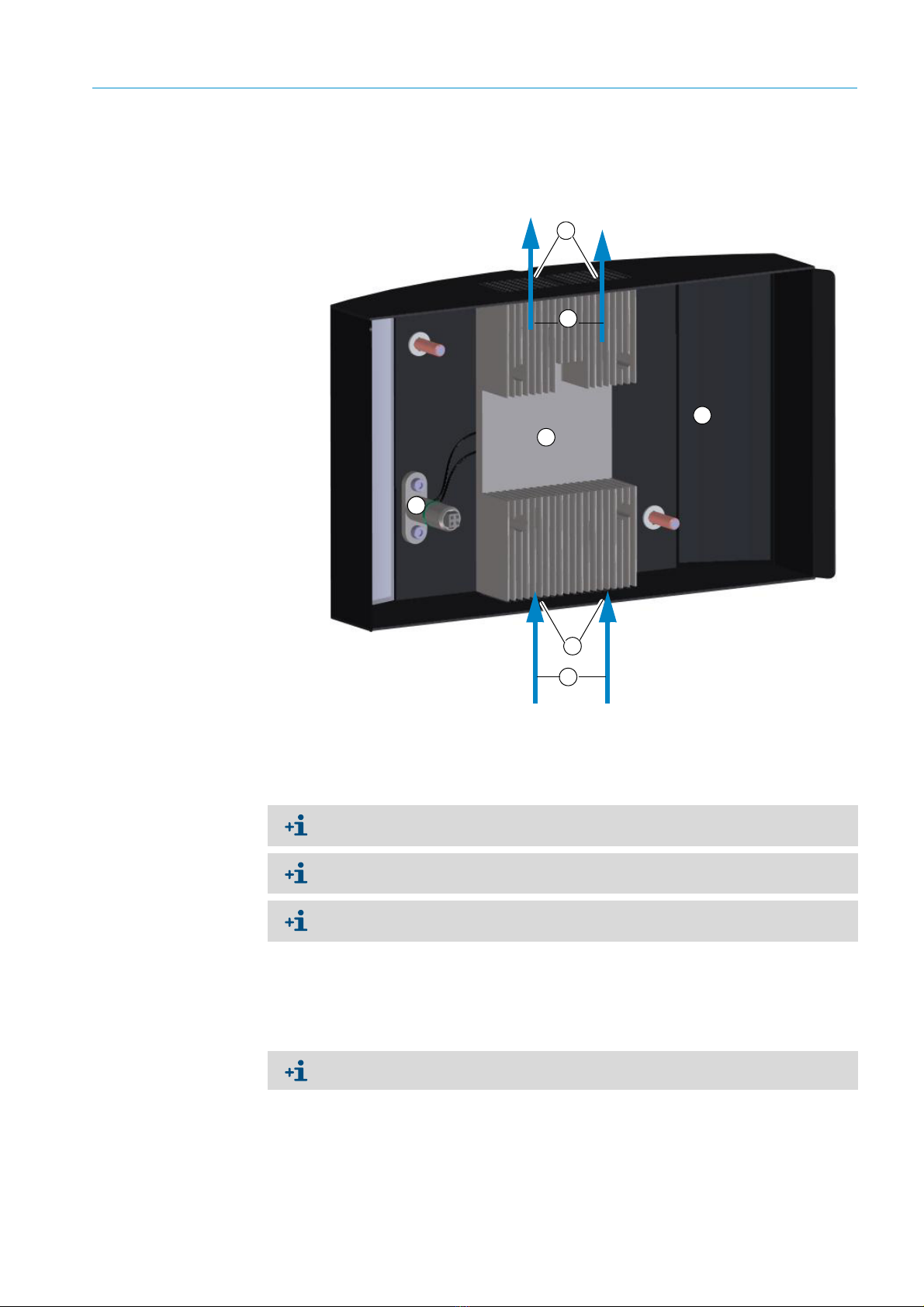
2.2.4 Interior view of the VISIC50SF
Fig. 7: Interior view - enclosure, complete
Enclosure cover
Rear enclosure panel with mounting bracket
Measuring unit
1
2
3
The enclosure cover can be held on the rear enclosure panel for maintenance purposes.

17
8016984/1DPO/V2-0/2023-07| SICK O P E R A T I N G I N S T R U C T I O N S | VISIC50SF
Subject to change without notice
PRODUCT DESCRIPTION 2
Fig. 8: Interior view - enclosure cover without heating
Interior view - enclosure cover with heating
see “VISIC50SF cover with heating element for fog dissipation”, page 15.
Interior view - measuring unit
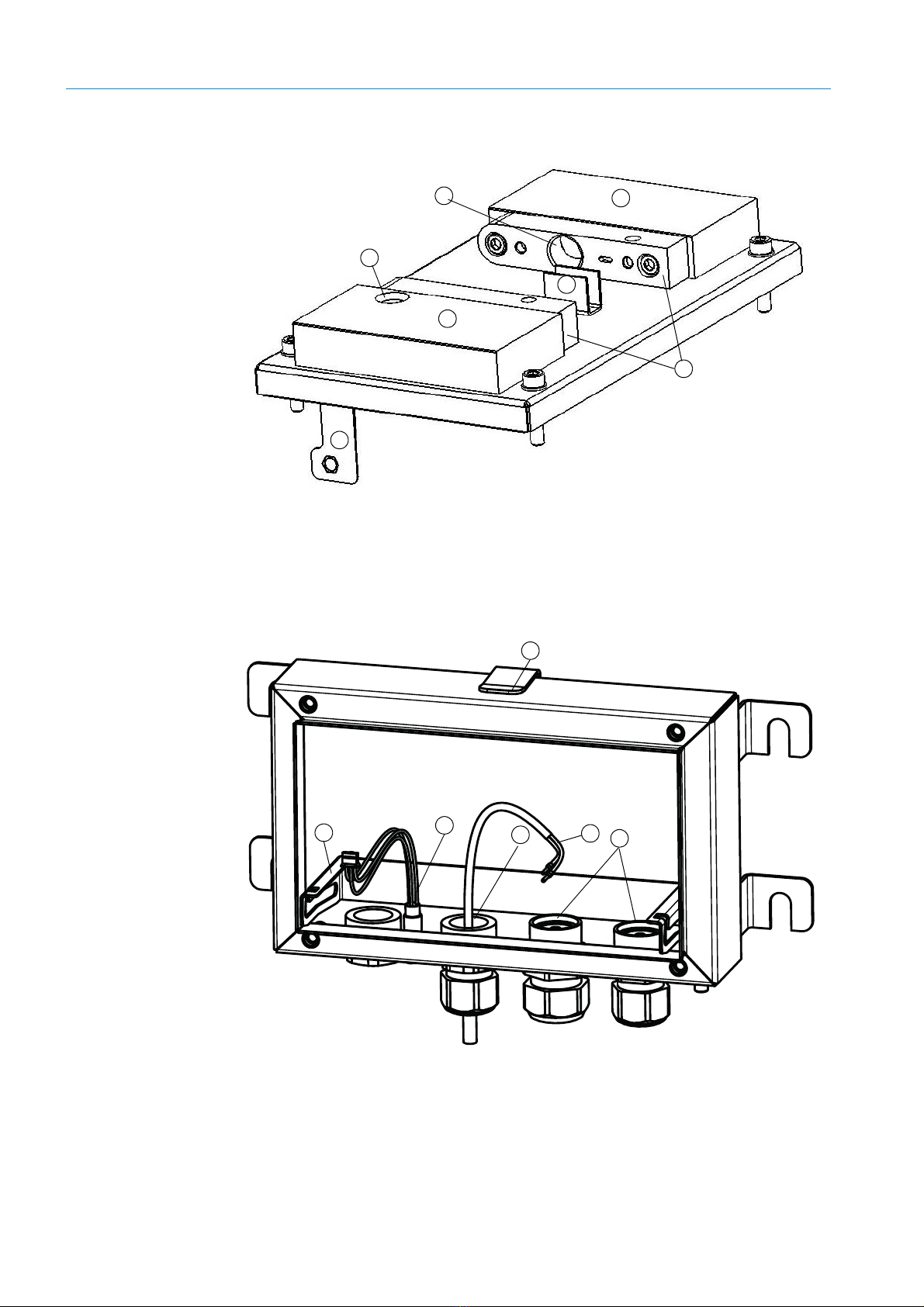
Fig. 9: Measuring unit - mainboard with display and keypad
Inlet opening for air to be
measured
1
Hinge fixture
Slot for Status LED
Wiring block for bus connections (RS-485)
Wiring block for 24 V and signals
Reset button
Display with keypad
1
23
4
5
6
18 8016984/1DPO/V2-0/2023-07| SICKO P E R A T I N G I N S T R U C T I O N S | VISIC50SF
Subject to change without notice
2PRODUCT DESCRIPTION
Fig. 10: Measuring unit
Fig. 11: Interior view - rear enclosure panel (with optional temperature sensor)
Hinge fixture
Sender side
Receiver side
Optical shielding
Dust shield tubes
Opening for plug contact for enclosure cover
Light trap
1
2
3
4
5
6
7
12345
Hinge rail for measuring unit
LED plug
Thread for optional temperature sensor
Optional temperature sensor
Cable glands
Bracket for enclosure cover
6
19
8016984/1DPO/V2-0/2023-07| SICK O P E R A T I N G I N S T R U C T I O N S | VISIC50SF
Subject to change without notice
PRODUCT DESCRIPTION 2
2.3 Interfaces
Standard:
●2 analog interfaces for measured value output
●3 digital interfaces for malfunction, maintenance requirement and limit value exceeded
●Alternatively: 3 digital interfaces for malfunction, exceeding pre-alarm, and exceeding
main alarm
●RS-485: Either Modbus-RTU or SICK bus to the TAD control unit
Optional:
●PROFIBUS DP-V0
2.3.1 Analog interfaces characteristics
The interfaces of the VISIC50SF provide 4 ... 20 mA signals. If an error exists on the
VISIC50SF, the relevant analog output changes to 1 mA.
The following formulas show the relation between the output current and the respective
measured variable:
Visibility:
Temperature:
2.3.2 Digital interfaces properties
If a device error is detected, an error is signaled via the malfunction relay. If no device error
exists, the malfunction relay is in a closed state. The relay opens when an error occurs.
2.3.3 Modbus-RTU interface characteristics
More information in Section Commissioning, see “Modbus-RTU (integrated in the
VISIC50SF standard version)”, page 40.
The switch to 1 mA only affects the analog output with a device error. The other analog
output continues to output a measured value between 4 ... 20 mA.
The analog interface can deliver a load of up to 500 Ohm.
The refresh rate is ≤1.6 seconds.
Messgröße (Sichttrübung)=(Ausgangsstrom − 4 )
16 ∗ Messbereichsendwert
Measured variable (visibility)
(Output current - 4mA)
x full-scale value
Messwert (Temperatur)=(െ4 )
16 כ100 െ30
Measured value (temperature)
(Output current - 4mA)

20 8016984/1DPO/V2-0/2023-07| SICKO P E R A T I N G I N S T R U C T I O N S | VISIC50SF
Subject to change without notice
3MOUNTING AND ELECTRICAL INSTALLATION
3 Mounting and electrical installation
3.1 Safety information
NOTICE: Preventive measures for operating safety
The VISIC50SF is normally used together with control technology.
▸Should a malfunction occur on the VISIC50SF, ensure this cannot lead to conditions
dangerous for traffic or can hinder traffic.
NOTICE: The system operator is responsible for the operating safety of the
device when integrated in a system
▸Observe the connection values in Section, see “Technical data”, page 106, when
integrating the device in a system.
WARNING: Preventive measures during mounting and installation
▸Observe the generally applicable regulations for protective clothes in tunnels.
▸Observe the regulations for personal safety (e.g., lane closure, warning devices).
NOTICE: Mounting of the VISIC50SF may be carried out by competent persons
only who, based on their device-specific training and knowledge of the device
as well as knowledge of the relevant regulations, can assess the tasks given
and recognize the hazards involved.
NOTICE: SICK original mounting material is recommended for safe mounting of
the VISIC50SF.
CAUTION: The connection unit and the control unit do not have independent
main power switches.
▸In accordance with EN 61010, the following must be ensured before installation:
●A main power switch is available in the tunnel.
●Service personnel can easily access the main power switch.
●The main power switch is marked as disconnecting device.
Table of contents


