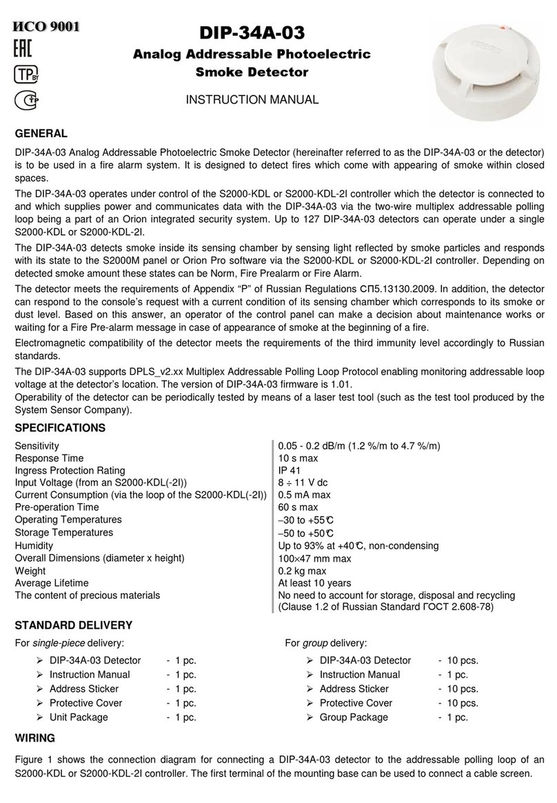
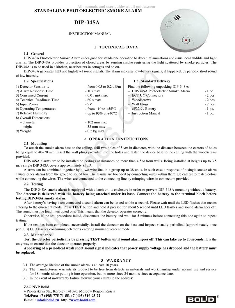
bolid DIP-34PA-03 User manual

DIP-34PA-03
Addressable Photoelectric Smoke Detector
INSTRUCTION MANUAL
GENERAL
DIP-34PA-03 Addressable Photoelectric Smoke Detector (hereinafter referred to as the DIP-34PA-03 or the detector) is
designed to be used in a fire alarm system in order to detect smoke inside enclosed premises by sensing light reflected
by smoke particles. The detector meets the requirements of Appendix “Р” of Russian Rules СП5.13130.2009.
The DIP-34PA-03 operates under control of a Signal-10 Intrusion and Fire Alarm Control Unit in an alarm loop of Type 14,
Fire Threshold Addressable. Up to ten detectors each having its own address from 1 to 10 can be brought into a single
Signal-10 alarm loop of Type 14. Each detector responds with its state to the Signal-10. These states can be Fire Alarm,
Trouble, Dusty, Norm, and Test. Electromagnetic compatibility of the detector meets the requirements for the third
resistance level.
The version of DIP-34PA-03 firmware is 1.00. Please read the Signal-10 User’s Manual to get more information about
DIP-34PA-03 operation.
The detector’s operability can be tested by means of a laser tester (such as the tester produced by System Sensor).
SPECIFICATIONS
Sensitivity 0.05 - 0.2 dB/m
Response Time 10 s max
Ingress Protection Rating IP 41
Input Voltage (via a Signal-10 alarm loop in threshold mode) 9 ÷ 30 VDC
Current Consumption (via an alarm loop of a Signal-10) 0.4 mA max in quiescent mode
Pre-operation Time 60 s max
The number of detectors per alarm loop Up to 10
Operating Temperatures −30 to +55°C
Storage Temperatures −50 to +50°C
Humidity 93% at 40°C, non-condensing
Overall Dimensions (diameter x height) 100 mm ×47 mm max
Weight 0.2 kg max
The detector doesn’t contain precious metals (Clause 1.2 of ГОСТ 2.608-78)
STANDARD DELIVERY
For single-piece delivery: For group delivery:
DIP-34PA-03 Detector - 1 pc. DIP-34PA-03 Detector - 10 pcs.
Instruction Manual - 1 pc. Instruction Manual - 1 pc.
Address Sticker - 1 pc. Address Sticker - 10 pcs.
Protective Cover - 1 pc. Protective Cover - 10 pcs.
Unit Package - 1 pc. Group Package - 1 pc.
WIRING
Figure 1 shows the standard wiring diagram to connect DIP-34PA-03
detectors into an alarm loop of the Type 14 of a Signal-10 control
unit. The first terminal of a detector base can be used to connect a
shield of the connecting wire.
Figure 1. Wiring Diagram

MOUNTING
When the detector is mounted on a ceiling, it is necessary to follow the requirements of Rules СП5.13130.2009, in
particular Table 13.3:
Height Average Area Monitored by
a Single Detector Distance
Between Detectors Between Detector and Wall
Below 3.5 m Up to 85 sq.meters 9.0 meters 4.5 meters
3.5 ÷6 m Up to 70 sq.meters 8.5 meters 4.0 meters
6 ÷10 m Up to 65 sq.meters 8.0 meters 4.0 meters
10 ÷12 m Up to 55 sq.meters 7.5 meters 3.5 meters
If cannot be installed on a ceiling, the DIP-34PA-03 can be mounted on wire ropes as well as on a wall, a column, or any
other structural. Installing point-type detectors on walls please follow the instructions of Appendix “П” of Rules
СП5.13130.2009.
Figure 2 shows two possible ways of attaching the detector. To attach the detector to a solid surface (variant A) use the
mounting base provided (see also the drilling pattern in Figure 3, at the left). Otherwise, a separately purchased mounting
kit MK-2 can be used to build the detector into a suspended ceiling (variant B). The size of the mounting hole is shown in
Figure 3, at the right.
1
:
DIP-34PA-03 Detector
2
:
Light Emitter
3
:
Alignment Guide
4
:
Mark and Bar,
OPEN HERE
5
:
Base Plate
6
:
MK-2 Suspended Ceiling Mounting Kit
(ordered separately)
Figure 3. Drilling Pattern
Figure 3 shows the drilling pattern to
install the detector for the variant A and
the diameter of the mounting hole in the
suspended ceiling for the variant B.
ATTENTION
To install the detector on the base plate, align the guide on the detector with the short guide of the base plate.
Then turn the detector clockwise until the detector guide is aligned with guide 3 as shown in Figure 2 (А).
INDICATION
Light Emitter Behavior Detector Status/Condition
Flashes once per 8 seconds Norm
Two flashes once per 8 seconds Fire Alarm or Test
Three flashes once per 8 seconds Service Required or Trouble
Three flashes (flickering) once per 2 seconds Indication of undefined (factory set) address in an addressable alarm
loop
Four flashes once per second Being connected to a non-addressable alarm loop or dc power supply;
or the DIP-34PA-03 is waiting for assigning an address
Figure 2

PROGRAMMING
In order the DIP-34PA-03 to operate properly within a Fire Threshold Addressable Alarm Loop of a Signal-10, the
detector must be assigned to a unique number from 1 to 10 within the alarm loop – the address which is stored in the
DIP-34PA-03 non-volatile memory. The detector is delivered without an address. Not assigning a detector connected to a
Fire Threshold Addressable Alarm Loop of a Signal-10 to an address is indicated by flickering of its light emitter once per
two seconds.
Assigning the DIP-34PA-03 to an Address
Bring the detector into a disarmed alarm loop of the Type 1 of a Signal-10 or to a 10V÷12V power supply. In 6 seconds
the detector’s light emitter will flash four times once per second indicating the detector’s being ready for assigning an
address. Push the light emitter and release after it lights up. Then press the light emitter again the number of times which
is equal to the required address (1 to 10). In 5 seconds the light emitter shall flash the number of times which is equal to
the current address, and then the detector lights up for a half of second.
Auto Assigning the DIP-34PA-03 to a First Vacant Address in a Loop
Bring the DIP-34PA-03 with pressed light emitter into an addressable alarm loop of Type 14 of the Signal-10. In three
seconds the light emitter illuminates for 1 second and shuts down indicating address’s being assigned. For example, if the
loop has already contained detectors with addresses 1, 2, 3, and 5 then the current detector will be assigned to the
address of 4.
How to Find Out the Address of the DIP-34PA-03
Bring the detector into a disarmed alarm loop of the Type 1 of a Signal-10 or to a 10V÷12V power supply. In 6 seconds
the detector’s light emitter will flash four times once per second indicating the detector’s being ready for assigning an
address. Push the light emitter and release when it lights up. In 5 seconds the light emitter shall flash the number of times
which is equal to the current address, and then the detector lights up for a half of second.
DIP-34PA-03 ROUTINE TESTING
Before testing DIP-34PA-03, please disconnect executive outputs of all system devices and modules that can
release an extinguishing agent or activate light and sound alarms. Notify the fire department and persons
where the audible signals can be heard.
After testing verify that all the detectors are ready to operate properly. Then restore operability of all the system
components disconnected before testing and inform the relevant departments about completing the test.
To test the DIP-34PA-03 detector, arm the alarm loop with the connected detector. Before arming the alarm loop should
be in the Norm state indicating this state by light emitter’s flashing once per 8 seconds.
Take a spray can of smoke detector test aerosol and spray some of the test material into the detector. (Or perform a
simplified test just by pressing on the detector’s light emitter for 2 to 5 seconds or by lighting the emitter with the laser
beam of a remote laser tester.)
The network controller shall display Fire Alarm message (or Test message in case of a simplified test) for the device with
the address of the DIP-34PA-03. The detector’s light emitter shall flash doubly every 8 seconds.
If no messages mentioned above are indicated then the detector is non-functioning and must be replaced.
Test tools are not provided with the detector and should be purchased aside.
MAINTENANCE
Please test the detector operability annually as said above.
When a Service Required message is received from the detector, remove pollution from the detector smoke chamber.
WARNINGS
To avoid contamination of the detector please DO NOT remove protective cover until the environment
is cleaned up from dust and debris.
DO NOT remove the detector PCB because this automatically cancels the warranty.
DO NOT mount the detector within the premises where air velocity values exceed 15 m/s.

WARRANTY
The average lifetime of the detector is at least 10 years.
The manufacturer warrants its product to be free from defects in materials and workmanship under normal use and
service for 18 months since putting it into operation, but no more than 24 months since the acceptance date.
In case of difficulties in programming or operating the product, please contact Technical Support by calling
In the event of in-warranty failure forward your claims to the address:
ZAO NVP Bolid
4 Pionerskaya Str., Korolev 141070, Moscow Region, Russia
Tel./Fax: (495) 775-71-55 (PBX), 777-40-20, 516-93-72
E-mail: info@bolid.ru,Technical Support: support@bolid.ru, http://bolid.ru.
CONFORMITY CERTIFICATES
The detector is approved by Conformity Certificate No. C-RU.ЧС13.В.00149.
Conformity Declaration ТС №RU Д-RU.МЕ61.В.00312 certifies that the detector meets the requirements of Technical
Regulations of Custom Union TR CU 020/2011.
Production of the detector is certified in line with Russian Standard ГОСТ ISO 9001 – 2011 by Conformity Certificate
№РОСС RU.ИК32.К00153.
ACCEPTANCE CERTIFICATE
The DIP-34PA-03 Addressable Photoelectric Smoke Detectors (the serial numbers are specified on the cases of the
detectors and written to the microprocessor memory) are qualified as proper for operation and packaged by CJSC NVP
“Bolid”.
Responsible for acceptance and packaging
QCD ________________________________________ ____________________________
Full Name Date, Month, Year
Other bolid Smoke Alarm manuals