Sidamo PE 22 A User manual
User’s manual PE22A
1
USER’S MANUAL
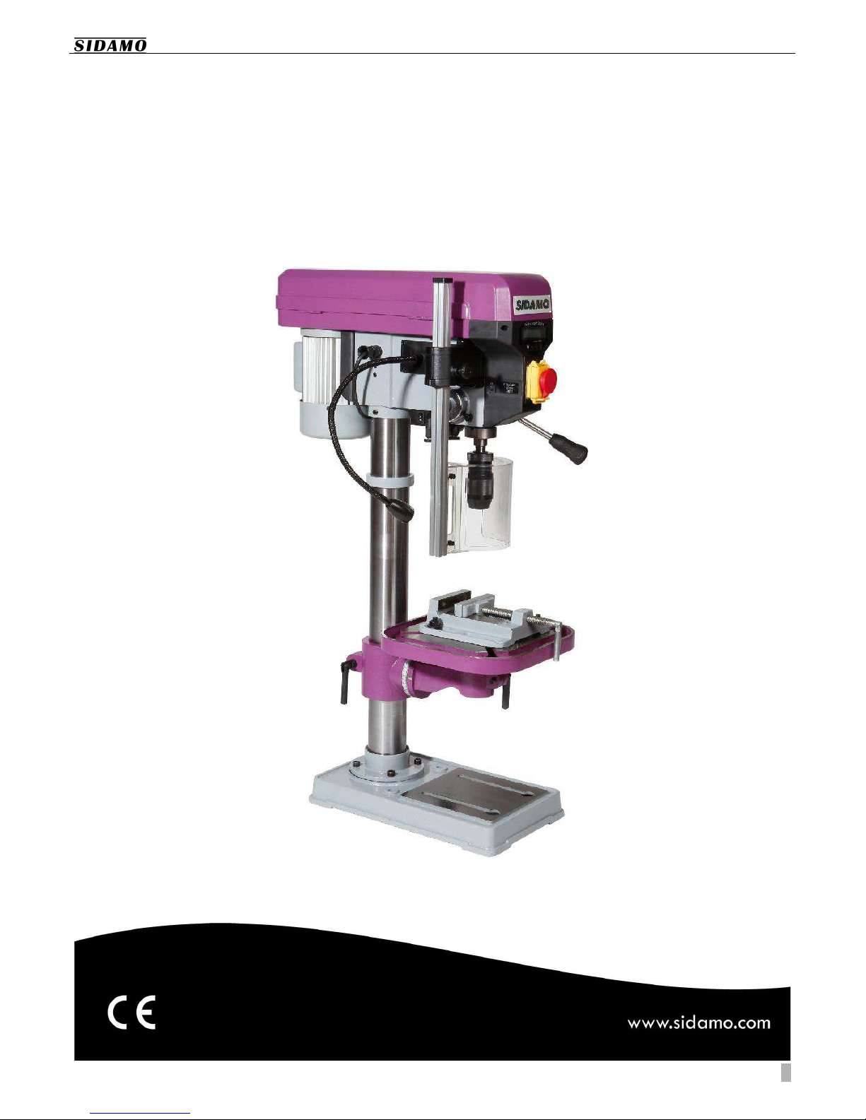
PE 22 A
BENCH DRILLING MACHINE
Original manual

User’s manual PE22A
2
CONTENTS
1.
1.1.
1.
INTRODUCTION
INTRODUCTIONINTRODUCTION
INTRODUCTION ................................
................................................................
................................................................
................................................................
................................................................
................................................................
................................................................
................................................................
................................................................
................................................................
................................................................
................................................................
..........................................
....................
..........3
33
3
2.
2.2.
2.
WARNING SIGNS
WARNING SIGNSWARNING SIGNS
WARNING SIGNS................................
................................................................
................................................................
................................................................
................................................................
................................................................
................................................................
................................................................
................................................................
................................................................
................................................................
................................................................
.......................................
..............
.......3
33
3
2.1.
WARNING SIGNS RELATED TO T E SAFETY OF T E MAC INE.............................................................................................................3
2.2.
WARNING SIGNS USED IN T IS MANUAL.......................................................................................................................................................3
3.
3.3.
3.
SAFETY
SAFETYSAFETY
SAFETY................................
................................................................
................................................................
................................................................
................................................................
................................................................
................................................................
................................................................
................................................................
................................................................
................................................................
................................................................
..........................................................
....................................................
..........................4
44
4
3.1.
GENERAL SAFETY INSTRUCTIONS.......................................................................................................................................................................4
3.2.
PARTICULAR SAFETY INSTRUCTION..................................................................................................................................................................5
3.3.
PROTECTION OF T E OPERATOR......................................................................................................................................................................... 6
4.
4.4.
4.
DESCRIPTION AND OPER
DESCRIPTION AND OPERDESCRIPTION AND OPER
DESCRIPTION AND OPERATING
ATINGATING
ATING................................
................................................................
................................................................
................................................................
................................................................
................................................................
................................................................
................................................................
................................................................
................................................................
............................................
........................
............6
66
6
4.1.
PURPOSE OF T E MAC INE ..................................................................................................................................................................................6
4.2.
SPECIFICATIONS.......................................................................................................................................................................................................... 6
4.3.
MAC INE OVERVIEW ................................................................................................................................................................................................7
5.
5.5.
5.
INSTALLATION
INSTALLATIONINSTALLATION
INSTALLATION ................................
................................................................
................................................................
................................................................
................................................................
................................................................
................................................................
................................................................
................................................................
................................................................
................................................................
................................................................
............................................
........................
............8
88
8
5.1.
PACKING..................................................................................................................................................................................................... 8
5.2.
TRANSPORT AND ANDLING ...........................................................................................................................................................8
5.3.
INSTALLING T E MAC INE.................................................................................................................................................................8
5.4.
ASSEMBLING ............................................................................................................................................................................................ 9
5.5.
ELECTRICAL CONNECTION...............................................................................................................................................................12
5.6.
TEST AND INITIAL INSPECTION PRIOR TO USING T E EQUIPMENT FOR T E FIRST TIME...................................12
6.
6.6.
6.
OPERATING T E BENC
OPERATING T E BENC OPERATING T E BENC
OPERATING T E BENC DRILLING MAC INE
DRILLING MAC INEDRILLING MAC INE
DRILLING MAC INE................................
................................................................
................................................................
................................................................
................................................................
................................................................
................................................................
................................................................
...............................................
..............................
...............13
1313
13
6.1.
CONTROL PANEL.................................................................................................................................................................................. 13
6.2.
RETURN SPRING OF T E SPINDLE...............................................................................................................................................13
6.3.
DRILLING DEPT .................................................................................................................................................................................. 13
6.4.
PROTECTIVE S IELD ...........................................................................................................................................................................14
6.5.
TABLE........................................................................................................................................................................................................ 15
6.6.
ASSEMBLING AND DISMANTLING T E TOOL.......................................................................................................................... 16
6.7.
SELECTING ROTATING SPEEDS OF T E SPINDLE................................................................................................................... 17
6.8.
LASER DEVICE........................................................................................................................................................................................ 19
6.9.
DIGITAL DISPLAY..................................................................................................................................................................................19
6.10.
DRILLING PROCEDURE ......................................................................................................................................................................20
6.11.
STORING T E MAC INE W EN IT IS NOT USED.................................................................................................................... 20
6.12.
TROUBLES OOTING............................................................................................................................................................................21
7.
7.7.
7.
MAINTENANCE
MAINTENANCEMAINTENANCE
MAINTENANCE................................
................................................................
................................................................
................................................................
................................................................
................................................................
................................................................
................................................................
................................................................
................................................................
................................................................
................................................................
........................................
................
........23
2323
23
7.1.
DAILY MAINTENANCE........................................................................................................................................................................23
7.2.
WEEKLY MAINTENANCE .................................................................................................................................................................. 23
7.3.
MONT LY MAINTENANCE............................................................................................................................................................... 23
7.4.
6-MONT MAINTENANCE................................................................................................................................................................23
8.
8.8.
8.
EXPLODED VIEW
EXPLODED VIEWEXPLODED VIEW
EXPLODED VIEW................................
................................................................
................................................................
................................................................
................................................................
................................................................
................................................................
................................................................
................................................................
................................................................
................................................................
................................................................
.....................................
..........
.....24
2424
24
9.
9.9.
9.
ELECTRICAL CIRCUIT
ELECTRICAL CIRCUITELECTRICAL CIRCUIT
ELECTRICAL CIRCUIT ................................
................................................................
................................................................
................................................................
................................................................
................................................................
................................................................
................................................................
................................................................
................................................................
.............................................................
..........................................................
.............................26
2626
26
10.
10.10.
10.
NOISE LEVEL
NOISE LEVELNOISE LEVEL
NOISE LEVEL................................
................................................................
................................................................
................................................................
................................................................
................................................................
................................................................
................................................................
................................................................
................................................................
................................................................
................................................................
.............................................
..........................
.............27
2727
27
11.
11.11.
11.
VIBRATIONS LEVEL
VIBRATIONS LEVELVIBRATIONS LEVEL
VIBRATIONS LEVEL................................
................................................................
................................................................
................................................................
................................................................
................................................................
................................................................
................................................................
................................................................
................................................................
................................................................
................................................................
.................................
..
. 27
2727
27
12.
12.12.
12.
PROTECTION OF T E EN
PROTECTION OF T E ENPROTECTION OF T E EN
PROTECTION OF T E ENVIRONMENT
VIRONMENTVIRONMENT
VIRONMENT ................................
................................................................
................................................................
................................................................
................................................................
................................................................
................................................................
................................................................
..............................................................
............................................................
..............................27
2727
27
13.
13.13.
13.
GUARANTEE
GUARANTEEGUARANTEE
GUARANTEE ................................
................................................................
................................................................
................................................................
................................................................
................................................................
................................................................
................................................................
................................................................
................................................................
................................................................
................................................................
.............................................
..........................
.............27
2727
27
14.
14.14.
14.
DECLARATION OF CONFO
DECLARATION OF CONFODECLARATION OF CONFO
DECLARATION OF CONFORMITY
RMITYRMITY
RMITY ................................
................................................................
................................................................
................................................................
................................................................
................................................................
................................................................
................................................................
................................................................
................................................................
.......................................
..............
.......28
2828
28

User’s manual PE22A
3
1.
1.1.
1.
INTRODUCTION
INTRODUCTIONINTRODUCTION
INTRODUCTION
For safety reasons, please careful
For safety reasons, please carefulFor safety reasons, please careful
For safety reasons, please carefully read these instructions, prior to using this machine.
ly read these instructions, prior to using this machine.ly read these instructions, prior to using this machine.
ly read these instructions, prior to using this machine.
Serious injuries to persons or damages to the machine may be caused by the non
Serious injuries to persons or damages to the machine may be caused by the nonSerious injuries to persons or damages to the machine may be caused by the non
Serious injuries to persons or damages to the machine may be caused by the non-
--
-observance of these instructions
observance of these instructionsobservance of these instructions
observance of these instructions.
..
.
This manual is intended to be used by operators, setters
and service engineers.
This manual is an important part of your equipment. It
provides rules and guidance to help you safely operating this
machine. You must read this manual and make sure of the
correct procedures and functions before operating the
machine. For your own safety, you must read these
precautions carefully and follow the instructions described
below.
These instructions must be followed anytime when
operating and servicing the machine. Serious injury and/or
failure of the machine may occur if operators fail in
observing safety guidance and instructions and operate the
machine in a wrong and different way from the one
described in this manual.
Please keep the manual with the machine or in a safe place
to make it available anytime. Make sure any person involved
in operating this machine can consult this manual. In case
this manual is damaged or lost, please contact us or your
dealer to be provided with a new manual.
Always use genuine SIDAMO parts and components.
Replacing SIDAMO parts and components by improper
parts may damage the machine and cause serious injuries
to operators.
This manual describes the safety instructions to be applied
by the operator. Both the employer and operators are
responsible, according to the article L.4122-1 of Labour
Laws, to take care of their health and safety and of the
health and safety of any other person involved by any action
or omission related to instructions given to them.
The employer is in charge of performing the assessment of
all particular risks related to the activity of his/her company.
e/she must train workers to operating the machine and
to the prevention of risks and provide with appropriate
information and instructions all workers in charge of
operating or servicing working equipments.
2.
2.2.
2.
WARNING SIGNS
WARNING SIGNSWARNING SIGNS
WARNING SIGNS
2.1.
2.1.2.1.
2.1.
WARNING SIGNS REL
WARNING SIGNS RELWARNING SIGNS REL
WARNING SIGNS RELATED TO T E SAFETY O
ATED TO T E SAFETY OATED TO T E SAFETY O
ATED TO T E SAFETY OF T E MAC INE
F T E MAC INEF T E MAC INE
F T E MAC INE
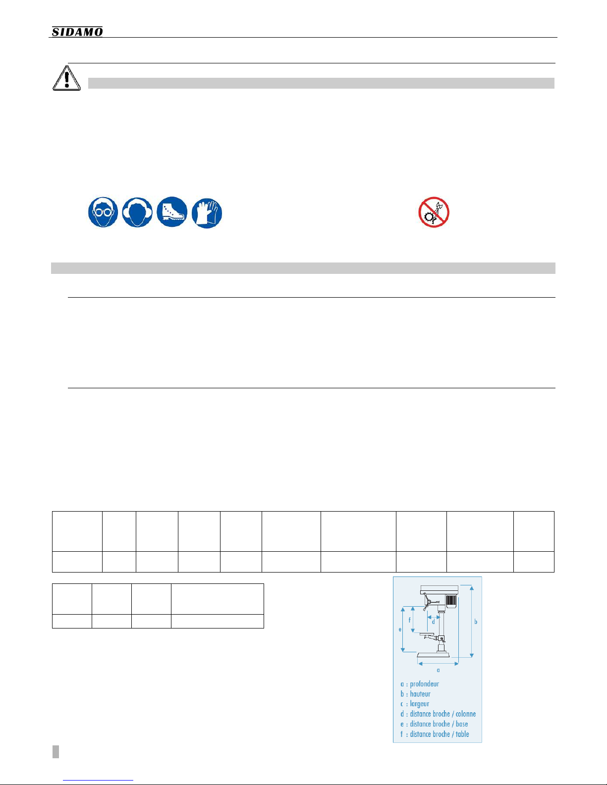
Meaning of the safety signs attached to the machine (They must remain clean. Replace them immediately in case they are peeled
off or illegible) :
Always wear protective goggles
Always wear ear protection
Carefully read the User’s Manual
Always wear protective shoes
Do not wear loose clothes, loose sleeves, jewels,
bracelets, watches, rings, …
Wear a hair covering to protect long hair
Wear protective gloves
We do not recommend wearing gloves when
machining. But we recommend wearing gloves
when cleaning, the machine being stopped, and
for any operation presenting any risk of cut, burn,
pinching … Rotation direction of the spindle
2.2.
2.2.2.2.
2.2.
WARNING SIGNS USED I
WARNING SIGNS USED IWARNING SIGNS USED I
WARNING SIGNS USED IN T IS MANUAL
N T IS MANUALN T IS MANUAL
N T IS MANUAL
Straight hazard for human persons and the
machine
The machine and its vicinity may be damaged
Technical ability level : operator, user
Minimal number of persons required to perform
some operations
Technical ability level : setter, service
Technical ability level : maintenance agent
Note
Only low voltage qualified and authorized workers should be allowed to perform interventions on the electrical
Only low voltage qualified and authorized workers should be allowed to perform interventions on the electrical Only low voltage qualified and authorized workers should be allowed to perform interventions on the electrical
Only low voltage qualified and authorized workers should be allowed to perform interventions on the electrical
circuit.
circuit.circuit.
circuit.

User’s manual PE22A
4
3.
3.3.
3.
SAFETY
SAFETYSAFETY
SAFETY
3.1.
3.1.3.1.
3.1.
GENERAL SAFETY INSTR
GENERAL SAFETY INSTRGENERAL SAFETY INSTR
GENERAL SAFETY INSTRUCTIONS
UCTIONSUCTIONS
UCTIONS
Always follow the basic safety instructions to reduce risks of fire, el
Always follow the basic safety instructions to reduce risks of fire, elAlways follow the basic safety instructions to reduce risks of fire, el
Always follow the basic safety instructions to reduce risks of fire, electric shock, mechanical crash and injury for any
ectric shock, mechanical crash and injury for any ectric shock, mechanical crash and injury for any
ectric shock, mechanical crash and injury for any
person using power tools
person using power toolsperson using power tools
person using power tools.
..
.
This manual considers only reasonably predictable
behaviours.
Our machines are designed keeping first in mind the safety
of operators.
We accept no responsibility for any damage cause by the
lack of experience, any improper use of the machine and/or
the machine being damaged and/or instructions provided
by this manual not being followed.
Accidents always happen following an improper use or
because the User’s Manual was not read and understood.
We remind you that in case changes are performed on the
machine, we will be freed from our obligations.
Before starting operating the machine, always check that
guards are in place and in working condition.
Make sure moving parts run correctly, that no element is
damaged and that the machine runs correctly when it is
commissioned.
Only authorized and qualified workers should be allowed to
repair or replace faulty parts.
Keep the vicinity of the machine tidy. Put everything in order.
Make sure the operator can see the entire working area
from the working station.
Untidy working areas and benches are hazardous and can
cause serious injuries.
Never use the machine outdoor ; never expose it to rain and
damp, or to an atmosphere containing flammable fluids.
Provide good lighting conditions to the machine.
No worker under the age of eighteen is allowed to operate
the machine.
Keep children, animals and unauthorized persons away from
the working area. They are not allowed to touch either tools
or electric cables.
Never leave a running machine unattended. Always switch
the machine off. Never leave the machine until it comes to a
full stop.
Never force a tool. It will do the job better and be
safer if it used at the rate it was designed for.
Do not force small tools to perform a machining that should
be done by a larger tool.
Use the right tool and do not use tools for a job they were
not designed for.
Never damage electric cables.
Never pull the power cable to unplug the machine.
Keep the main power cable away from heat sources, greasy
parts and/or sharp edges.
Never use the power cable in wet conditions and protect it
from any damage.
Regularly check the condition of the power cable. In case it
is damaged, have it repaired by an authorized repairer. Only
an authorized company should replace faulty switches.
Never try to run the machine in case the main switch is out
of work.
Do not overestimate your strength.
Do not overreach. Never lose balance.
Always be aware. Use common sense and do not run the
machine when you are tired.
Always use both hands to run the machine.
Use only recommended accessories. Using accessories
different from the ones recommended in this manual may
be hazardous.
The user is responsible for the machine and must make
sure that :
Only qualified, authorized and trained workers can
use the drilling machine.
Safety instructions are followed.
Users have read and understood the safety
instructions.
Users have read and understood the User’s
Manual.
Responsibilities for servicing and possibly repairing
have been correctly assigned and followed.
Failures and faults have immediately been
communicated to an authorized repairer or to your
dealer.
The drilling machine is used for applications
described in this manual.
Do not use the machine for any application other
than that it was designed for. Any other use is
hazardous.
Never remove or bypass mechanical and/or
electrical protections.
Never try to modify or retrofit the machine.
SIDAMO accepts no responsibility for any damage caused to
persons, animals or objects, and resulting from the non-
observance of the safety instructions described in this
manual.

User’s manual PE22A
5
3.2.
3.2.3.2.
3.2.
PARTICULAR SAFETY IN
PARTICULAR SAFETY INPARTICULAR SAFETY IN
PARTICULAR SAFETY INSTRUCTION
STRUCTIONSTRUCTION
STRUCTION
Particular safety instructions related to bench drilling machines.
Particular safety instructions related to bench drilling machines.Particular safety instructions related to bench drilling machines.
Particular safety instructions related to bench drilling machines.
Prior to using this machine, check it has been correctly
assembled.
Do not connect to power if the drilling machine has not been
installed on a flat and stable place, showing no obstacles
and where lighting conditions are correct.
Do not use the machine if the protective guard of the belts
is not fitted.
Adjust the protective shield to prevent any access to the
non-working part of the tool.
Do not use any damaged or warped drill.
Make sure you have selected the right drill and the right
rotating speed, in relation with the material to drill.
Check whether the tension of belts is correct.
Use only adapted drilling rotating speeds. Always select a
speed when the machine has stopped.
Make sure the drill is firmly clamped into the chuck.
Do not touch the drill when it is rotating.
Always wear protective goggles.
In any case, always be concentrated on the work.
We do not recommend wearing gloves when machining.
We do not recommend wearing gloves when machining. We do not recommend wearing gloves when machining.
We do not recommend wearing gloves when machining.
Wear gloves when cleaning.
Always stop the machine and wear protective gloves when
performing hazardous tasks, presenting risks of burn, cut,
pinching, entanglement, winding, crushing, especially when
loading and unloading the tool, when handling the table, the
vice, the clamps, the workpiece.
Do not rush as it is very often a waste of time : the tool
heats, it becomes blunted and it requires grinding. The work
is not well done. There are more risks of accidents.
Always wear an ear protection.
Never hold the workpiece by hand. Always clamp the
workpiece using adapted work-holding devices, such as vices
and clamps.
Thin metal sheets are the most hazardous work pieces :
- They can cut, as they are very thin.
- The drill tends to plunge once it goes through the metal
sheet.
- Offset holes increase hazards as the workpiece, when
rotating, moves along a circle. Fingers, wrists, forearms
and event the chest are particularly exposed.
Use fixtures and clamps :
- Support fixture for flexible work pieces and work pieces
with steps.
- Guiding bush to drill small holes in a thin sleeve.
To not drill the table, adjust the table or the drilling depth.
The working table must remain clean and not populated.
Wear a breathing apparatus to reduce the risk of breathing
harmful dusts.
Prevent coolant from overflowing all around the machine, as
it is a very slippery product.
Prior to changing the workpiece or performing any
positioning or any removal of material wastes, always stop
the machine by using the Emergency Stop Slam button with
lock.
To use this Emergency Stop Slam button with lock, simply
close the cover of the control box, but do not lock it.
Prior to performing any important operation (maintenance,
servicing, …) always unplug the machine from the main
power.
Do not install additional equipments to perform tasks they
were not designed for.
Using improper tools is hazardous.
Make sure the guard of the fan is clean. Do not cover it.
Otherwise the machine could not be correctly operated.
The drill must remain perfectly clean.
Do not clean the drill when it is rotating.
The drill can become very hot during the machining. Before
replacing the drill, wait until it is cold.
When cleaning, first stop the machine and wear protective
goggles and gloves to remove chips. Collect them into tanks.
Do not use an air gun. Prefer using a vacuum cleaner, a
brush, a painting brush with long handle or a hook.
Never wash the machine using water under pressure as
water can get into electric parts.
Never use solvent or aggressive detergents.
When moving the machine, stop it and make sure all moving
parts are safely fixed.
Store the machine in a cool place, out of the reach of
children.
Accidents usually happen because :
There are no accessories used to properly hold the
workpiece.
Disorder : accessories, if present, are not set in
order, and the operator do not use them, as he
cannot find them.
azardous or inappropriate operating mode.
Insufficient training, learning and/or experience of
operators to use the machine.
Lack of protective guards during the operating of
the machine.
Loose cloths, no protective goggles when
performing some tasks.
User’s manual PE22A
6
3.3.
3.3.3.3.
3.3.
PROTECTION OF T E OP
PROTECTION OF T E OPPROTECTION OF T E OP
PROTECTION OF T E OPERATOR
ERATORERATOR
ERATOR
T
TT
To ensure operator’s safety, make sure that non
o ensure operator’s safety, make sure that nono ensure operator’s safety, make sure that non
o ensure operator’s safety, make sure that non-
--
-working parts are protected by a guard.
working parts are protected by a guard.working parts are protected by a guard.
working parts are protected by a guard.
This machine was designed to be operated by only one
operator.
The operator should wear adapted Personal Protective
Equipments, such as :
Protective goggles.
Ear protections.
Safety shoes.
Protective gloves.
The operator should wear tight clothes and should wear a
hair covering to protect long hair, if necessary.
For example, the operator should never wear :
Loose clothes or sleeves.
Bracelets, watch, ring, jewels.
Any other object subjected to be caught or
entangled by moving parts of the machine.
4.
4.4.
4.
DESCRIPTION AND OPER
DESCRIPTION AND OPERDESCRIPTION AND OPER
DESCRIPTION AND OPERATING
ATINGATING
ATING
4.1.
4.1.4.1.
4.1.
PURPOSE OF T E MAC I
PURPOSE OF T E MAC IPURPOSE OF T E MAC I
PURPOSE OF T E MAC INE
NENE
NE
The bench drilling machine PE22A is designed and
manufactured only to perform drilling, on a fixed station,
using a vertical stroke, on steel, ferrous and non-ferrous,
plastic and wooden work pieces.
When operating and maintenance are correct, the drilling
machine can provide many years of safe and consistent
work.
To do so, please thoroughly examine the different functions
of the machine.
4.2.
4.2.4.2.
4.2.
SPECIFICATIONS
SPECIFICATIONSSPECIFICATIONS
SPECIFICATIONS
Digital display of the drilling depth
Protective shield of the servo chuck
Drilling position laser device
LED lighting
Belt guard fitted with a safety grip micro switch
« ON/OFF» switch fitted with an under voltage coil
Emergency Stop Slam button with lock
Transmission using dented belts pulleys
Spindle fitted with ball bearings
Ferro steel column
Square table tilting up to 45°, fitted with a coolant
collector
Rack-drive table
Comes standard with a self-clamping chuck, a
chuck shank, a taper drift, a screw vice and a set of
clamps
Max. drilling
Max. drilling Max. drilling
Max. drilling
capacity
capacitycapacity
capacity
(mm)
(mm)(mm)
(mm)
Morse
Morse Morse
Morse
taper
tapertaper
taper
Column
ColumnColumn
Column
Ø
ØØ
Ø
(mm)
(mm) (mm)
(mm)
Spindle
Spindle Spindle
Spindle
stroke
strokestroke
stroke
(mm)
(mm)(mm)
(mm)
Number
Number Number
Number
of gears
of gearsof gears
of gears
Spindle speed
Spindle speed Spindle speed
Spindle speed
range
rangerange
range
(rpm)
(rpm)(rpm)
(rpm)
Dimensions
DimensionsDimensions
Dimensions
(L x x D)
(L x x D)(L x x D)
(L x x D)
(mm)
(mm)(mm)
(mm)
Motor
Motor Motor
Motor
power
powerpower
power
(kW)
(kW)(kW)
(kW)
Power
PowerPower
Power
Weight
WeightWeight
Weight
(kg
(kg(kg
(kg)
))
)
22 MT2 72 85 16 180 – 2770 430 x 980 x 660 0,55 1-phase 230V 49
d
dd
d
(mm)
(mm)(mm)
(mm)
e
ee
e
(mm)
(mm)(mm)
(mm)
f
ff
f
(mm)
(mm)(mm)
(mm)
Table
TableTable
Table
dimensions
dimensionsdimensions
dimensions
(mm)
(mm)(mm)
(mm)
160 630 440 286 x 286
User’s manual PE22A
7
4.3.
4.3.4.3.
4.3.
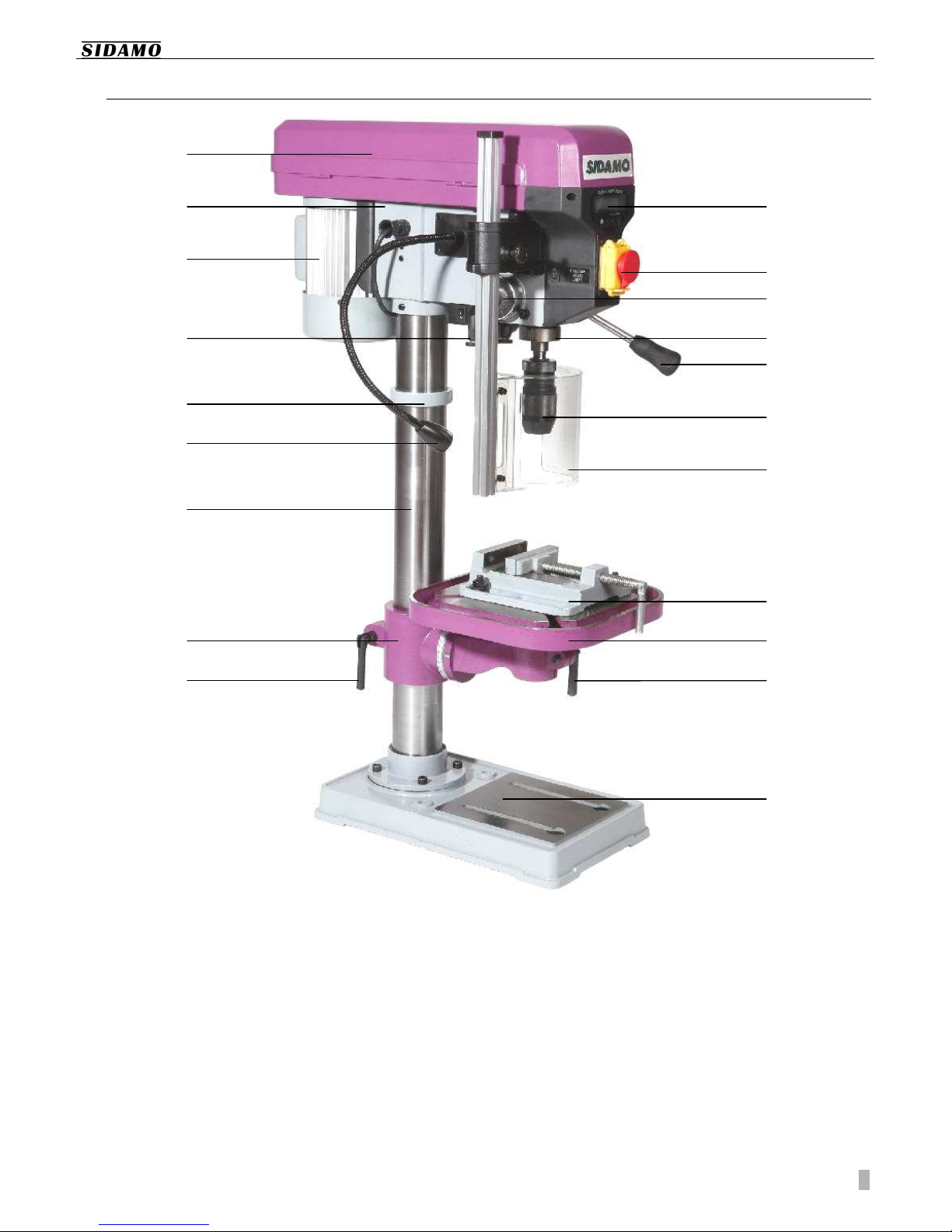
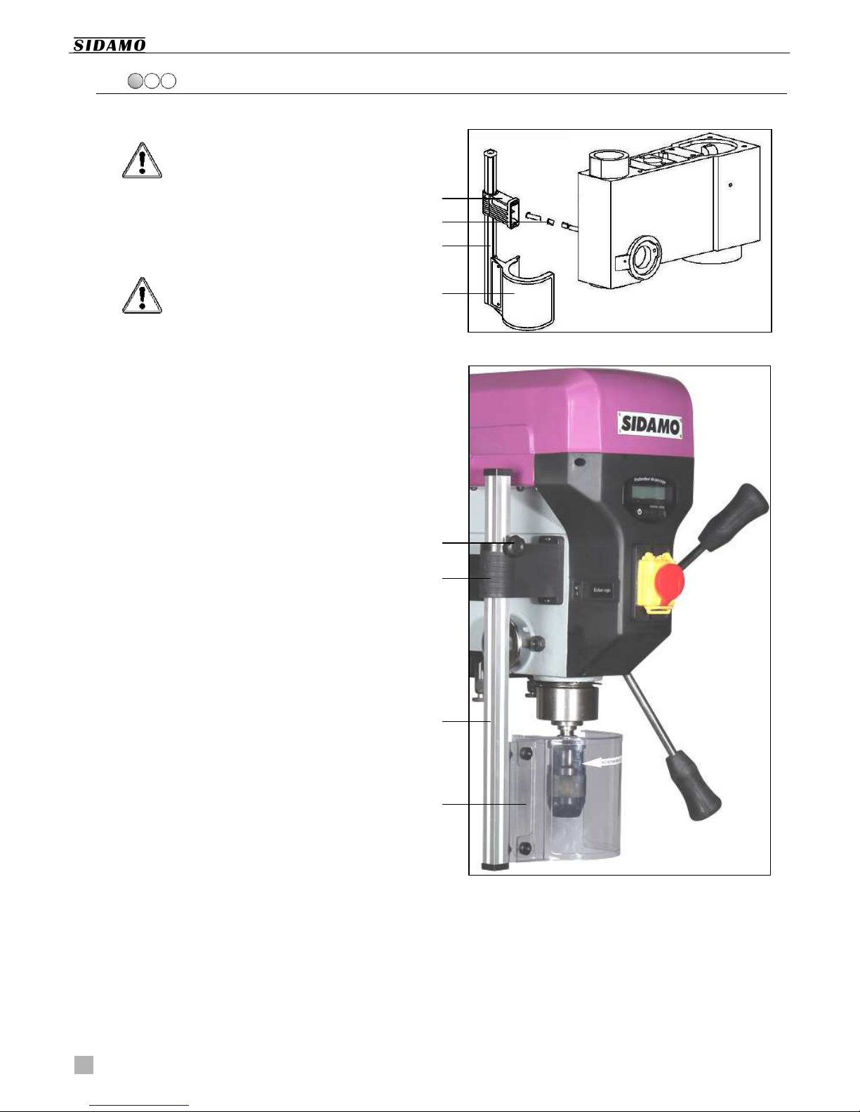
MAC INE OVERVIEW
MAC INE OVERVIEW MAC INE OVERVIEW
MAC INE OVERVIEW
1. Belt guard
2. ead of the drilling machine
3. Electric motor
4. Laser device
5. Rack ring
6. Light
7. Column
8. Support sleeve of the scale table
9. Lock lever of the support sleeve of the scale table
10. Base
11. Lock lever of table
12. Table
13. Vice
14. Servo polycarbonate shield
15. Chuck
16. Capstan wheel
17. Spindle
18. Return spring of spindle
19. Control box
20. Digital display
1
2
3
4
7
5
12
13
8
14
16
17
Figure 1
15
10
6
11
18
9
19
20

User’s manual PE22A
8
5.
5.5.
5.
INSTALLATION
INSTALLATIONINSTALLATION
INSTALLATION
5.1.
5.1.5.1.
5.1.
PACKING
PACKING PACKING
PACKING
The packing may include a desiccant bag. Discard it and keep out of reach of children.
The packing may include a desiccant bag. Discard it and keep out of reach of children.The packing may include a desiccant bag. Discard it and keep out of reach of children.
The packing may include a desiccant bag. Discard it and keep out of reach of children.
The drilling machine comes packed in a cardboard packing.
To move the drilling machine, use a pallet truck or a forklift
truck. Several persons are required to install the machine.
Take out each component of the drilling machine. Check
their condition and then assemble the drilling machine.
Please keep the manual with the machine or in a safe place
to make it available anytime.
In case the product is not in perfect condition or if some
parts are damaged or missing, please contact your dealer.
5.2.
5.2.5.2.
5.2.
TRANSPORT AND ANDL
TRANSPORT AND ANDL TRANSPORT AND ANDL
TRANSPORT AND ANDLING
INGING
ING
Only qualified and authorized persons can perform below operations.
Only qualified and authorized persons can perform below operations.Only qualified and authorized persons can perform below operations.
Only qualified and authorized persons can perform below operations.
The mass centre of this
The mass centre of thisThe mass centre of this
The mass centre of this machine is very high. Be careful as the machine can tip over.
machine is very high. Be careful as the machine can tip over. machine is very high. Be careful as the machine can tip over.
machine is very high. Be careful as the machine can tip over.
Control the good tightening of screws that fix the head on the column.
Control the good tightening of screws that fix the head on the column.Control the good tightening of screws that fix the head on the column.
Control the good tightening of screws that fix the head on the column.
Considering the weight of the machine (49 kg),
several persons, using an adapted lifting device, are
required to install the machine.
To lift the machine, use a slinging system (ex :
polyester cable, with lifting rings and a convenient capacity).
Position the lifting device as shown on next figure.
Make sure all moving parts are securely fixed and be very
careful when lifting the drilling machine. Keep any foreign
person away.
5.3.
5.3.5.3.
5.3.
INSTALLING T E MAC
INSTALLING T E MAC INSTALLING T E MAC
INSTALLING T E MAC INE
INEINE
INE
Only qualified and authorized persons can perform below operations.
Only qualified and authorized persons can perform below operations.Only qualified and authorized persons can perform below operations.
Only qualified and authorized persons can perform below operations.
Vicinity of the equipment :
Vicinity of the equipment :Vicinity of the equipment :
Vicinity of the equipment :
Main power should comply with the specifications
of the machine.
Ambient temperature : between +5°C and +35°C.
Relative umidity : not over 90%.
Sufficient ventilation of the workshop.
Good lighting conditions in the working area : min.
300 lux.
Consider the location of the machine in the room.
Movements and movings should be easy. Respect a
distance of min. 800 mm between the back of the machine
and the wall.
Several persons are required to install the machine.
Position the machine on a flat and horizontal
surface, so that it is level and as stable as possible.
Use a strong enough support base for the machine.
Drill the fixing holes in the support. They must match base
holes. Fix the machine.
Prior to tightening bolt, make sure the machine is level. To
adjust level, use adapted metal sheets (reference shims)
between the surface of the support and the feet.
To perform machining while respecting ergonomic criteria,
the vice plane should be ideally positioned at about 90/95
cm from the floor.
12

User’s manual PE22A
9
Cleaning a new machine :
Cleaning a new machine :Cleaning a new machine :
Cleaning a new machine :
All our machines are supplied with rustproof oil on
ground surfaces. Before using the machine, first
remove this oil, using a thinner. This is very
important. Please use extreme care when
performing this cleaning : jammings can occur if
this oil is not totally removed.
There should be no chips and no oil residues on the
surface of the clamping table.
Once the machine has been cleaned, apply a thin
film of oil onto all non-painted surfaces, using
medium-viscosity oil.
Clean the inner part of both spindle and chuck,
using a dry cloth and firmly insert the Morse taper
into the spindle. Then, insert firmly the chuck into
the shank of the Morse taper.
5.4.
5.4.5.4.
5.4.
ASSEMBLING
ASSEMBLING ASSEMBLING
ASSEMBLING
Only qualified and authorized persons can perform below operations.
Only qualified and authorized persons can perform below operations.Only qualified and authorized persons can perform below operations.
Only qualified and authorized persons can perform below operations.
Several persons are required to assemble
Several persons are required to assemble Several persons are required to assemble
Several persons are required to assemble the machine.
the machine.the machine.
the machine.
Figure 2
1. Install the base (9 fig.2) on a solid and flat surface.
2. Assemble the column (14 fig.2) to the base and fix
it using bolts (8 fig.2).

User’s manual PE22A
10
3. Insert the rack, in the right direction (6 fig.2), into
the support sleeve of the table (12 fig.2).
4. old the rack (teeth towards the inner right side of
the support sleeve of the table) and slide the
assembly into the column (14 fig.2).
5. Slide the rack ring (15 fig.2) on the column, the
chamfer being oriented downwards, to make sure
the top side of the rack is locked (value of the
clearance with the rack : 1 mm).
6. Tighten the screw of the ring.
7. Fit the table (10 fig.2) on its support (12 fig.2).
8. Fit the handle (13 fig.2) on the shaft of the support
sleeve of the table and tighten the screw.
9. Check whether you can move the table up and
down.
The ideal height between the table and the floor is
about 90/95 cm.
10. Fit the head (1 fig.2) on the column (at least two
persons are required).
11. Check whether the assembly of the head is correct.
12. To balance correctly the assembly, align the head
with the centreline of the base.
13. Tighten the screws to firmly hold the head in place.

User’s manual PE22A
11
14. Screw the three handles (2 fig.2) on the capstan
wheel, used to move the head down.
15. Connect the lamp to the terminals.
16. Fix it using convenient screws.
17. Connect the body of the protector to the terminals.
18. Fit the protective shield on the shield support, using
two screws.
19. Fit the assembly in the body of the protector.
20. Position the shaft and tighten the screw.
21. Clean the inner side of the chuck (5 fig.2).
22. Fit the chuck on the shank of the chuck (4 fig.2).
23. Clean the inner side of the spindle and the shank of
the chuck.
24. Fit the assembly shank of chuck + chuck into the
spindle.

User’s manual PE22A
12
5.5.
5.5.5.5.
5.5.
ELECTRICAL CONNECTIO
ELECTRICAL CONNECTIOELECTRICAL CONNECTIO
ELECTRICAL CONNECTION
NN
N
Only low voltage trained and authorized technicians should be allowed to perform interventions on the electric circuit
Only low voltage trained and authorized technicians should be allowed to perform interventions on the electric circuitOnly low voltage trained and authorized technicians should be allowed to perform interventions on the electric circuit
Only low voltage trained and authorized technicians should be allowed to perform interventions on the electric circuit.
..
.
POWER
POWERPOWER
POWER
Make sure the voltage of the motor matches the voltage of
the main power.
Perform the connection, using the power cable.
The power socket must match the plug of the machine.
The machine is connected to a power system. This system
must be connected to earth, according to in-force safety
regulations.
We remind the user that a magneto thermal breaker must
be installed before the electrical circuit to protect all
conductive devices against short-circuits and overloads.
This protection should always be selected according to the
electrical specifications of the machine, as stated on the
rate plate :
Voltage : one-phase 230 V
Frequency : 50 z
Rating : 2,6 A
Motor power : 0,55 kW
Power connections and extensions must be protected
against splashes and should be fitted onto dry surfaces.
Regularly inspect condition of the power cable, of the switch
and of the cable ducting.
Operating the machine, using a damaged power cable, is strictly prohibited.
Operating the machine, using a damaged power cable, is strictly prohibited.Operating the machine, using a damaged power cable, is strictly prohibited.
Operating the machine, using a damaged power cable, is strictly prohibited.
Always use a cable winder with both section and length adapted to the power
Always use a cable winder with both section and length adapted to the powerAlways use a cable winder with both section and length adapted to the power
Always use a cable winder with both section and length adapted to the power of the machine. Unwind completely the
of the machine. Unwind completely the of the machine. Unwind completely the
of the machine. Unwind completely the
cable.
cable.cable.
cable.
Never pull the cable to unplug the grinder. Always use the plug.
Never pull the cable to unplug the grinder. Always use the plug.Never pull the cable to unplug the grinder. Always use the plug.
Never pull the cable to unplug the grinder. Always use the plug.
Please check the spindle rotates clockwise, as shown on sign fixed on the front of the protective shield.
Please check the spindle rotates clockwise, as shown on sign fixed on the front of the protective shield.Please check the spindle rotates clockwise, as shown on sign fixed on the front of the protective shield.
Please check the spindle rotates clockwise, as shown on sign fixed on the front of the protective shield.
The guarantee does not cover dam
The guarantee does not cover damThe guarantee does not cover dam
The guarantee does not cover damages resulting from a poor connection
ages resulting from a poor connectionages resulting from a poor connection
ages resulting from a poor connection.
..
.
5.6.
5.6.5.6.
5.6.
TEST AND INITIAL INS
TEST AND INITIAL INSTEST AND INITIAL INS
TEST AND INITIAL INSPECTION PRIOR TO USI
PECTION PRIOR TO USIPECTION PRIOR TO USI
PECTION PRIOR TO USING T E EQUIPMENT FOR
NG T E EQUIPMENT FORNG T E EQUIPMENT FOR
NG T E EQUIPMENT FOR T E FIRST TIME
T E FIRST TIME T E FIRST TIME
T E FIRST TIME
Make sure all protections are in place and in
working condition.
Make sure moving parts correctly run and that no
part is damaged.
Check condition of the drill.
Make sure the head and the table are firmly fixed to
the column.
Make sure the bench drilling machine is located on
a flat and solid surface.
Perform a dry test : the machine should run
correctly.
Make sure the spindle goes down, the protective
shield can be adjusted and the table can go up and
down.
User’s manual PE22A
13
6.
6.6.
6.
OPERATING T E BENC
OPERATING T E BENC OPERATING T E BENC
OPERATING T E BENC DRILLING MAC INE
DRILLING MAC INEDRILLING MAC INE
DRILLING MAC INE
Prior to starting the drilling machine, make sure you are familiar with control devices
Prior to starting the drilling machine, make sure you are familiar with control devicesPrior to starting the drilling machine, make sure you are familiar with control devices
Prior to starting the drilling machine, make sure you are familiar with control devices.
..
.
Prior to any servicing or maintenance
Prior to any servicing or maintenancePrior to any servicing or maintenance
Prior to any servicing or maintenance, always unplug the machine.
, always unplug the machine., always unplug the machine.
, always unplug the machine.
6.1.
6.1.6.1.
6.1.
CONTROL PANEL
CONTROL PANEL CONTROL PANEL
CONTROL PANEL
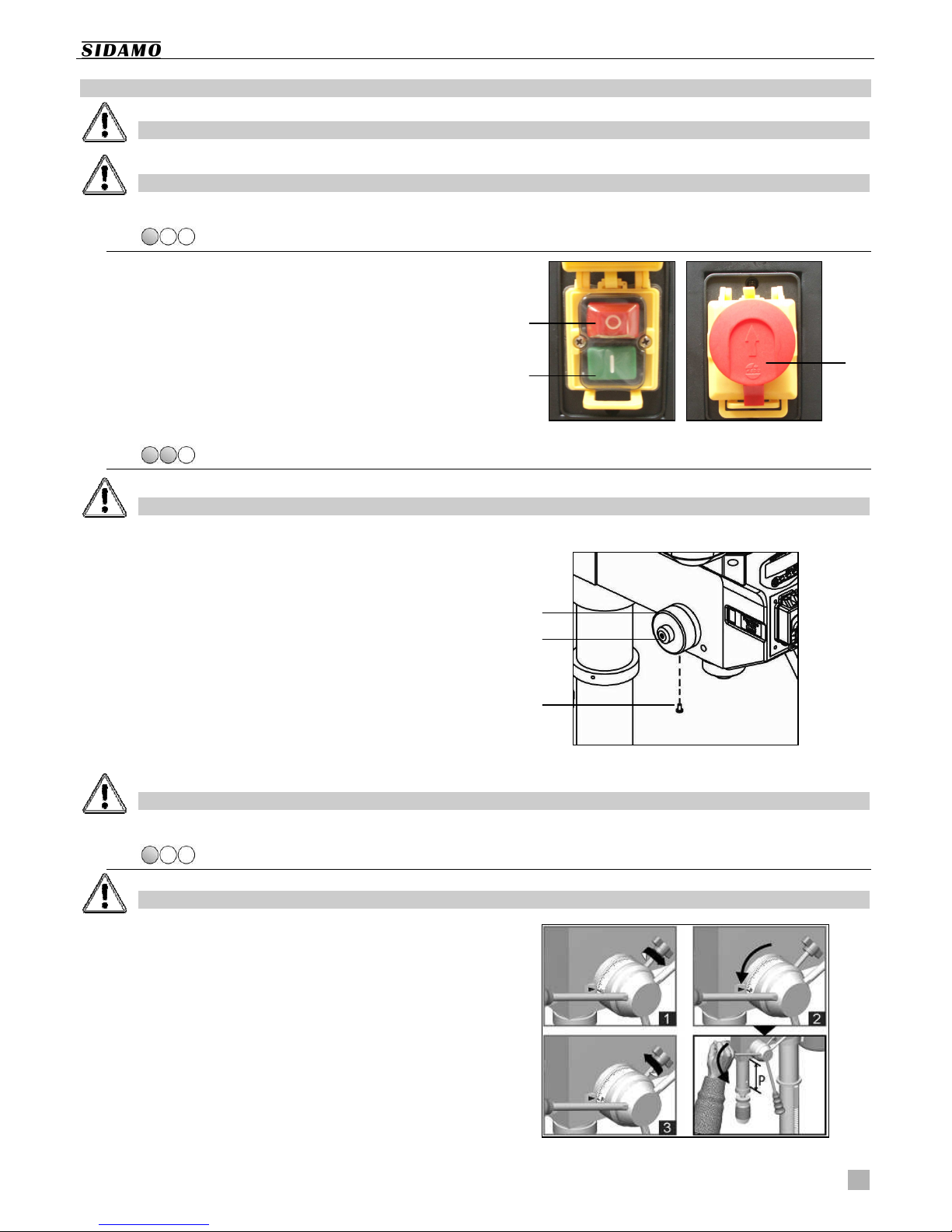
Control box :
Control box :Control box :
Control box :
A. Red Stop button « 0 »
B. Green Run button « I »
C. Emergency Stop slam button with lock
6.2.
6.2.6.2.
6.2.
RETURN SPRING OF T
RETURN SPRING OF T RETURN SPRING OF T
RETURN SPRING OF T E SPINDLE
E SPINDLEE SPINDLE
E SPINDLE
First switch off the machine prior to performing this operat
First switch off the machine prior to performing this operatFirst switch off the machine prior to performing this operat
First switch off the machine prior to performing this operation.
ion.ion.
ion.
The drilling machine is supplied with the spindle
counterbalanced by a spiral spring.
When the spindle cannot go up to its higher position,
adjusting the return spring of the spindle is possible :
1. Stop the machine.
2. Untighten the screw (A).
3. Untighten the screw (B).
4. Carefully rotate the casing (C) in the right direction
to tension, more or less, the spring (to tighten :
rotate anticlockwise). Be careful as the spring can
suddenly get out of the casing.
5. Tighten the screws.
6. Test whether the spindle can go up.
Do not move the spindle back too fast as it could be hazardous and could then threaten the lifespan of the spring.
Do not move the spindle back too fast as it could be hazardous and could then threaten the lifespan of the spring. Do not move the spindle back too fast as it could be hazardous and could then threaten the lifespan of the spring.
Do not move the spindle back too fast as it could be hazardous and could then threaten the lifespan of the spring.
6.3.
6.3.6.3.
6.3.
DRILLING DEPT
DRILLING DEPTDRILLING DEPT
DRILLING DEPT
First switch off the machine prior to performing this operation.
First switch off the machine prior to performing this operation.First switch off the machine prior to performing this operation.
First switch off the machine prior to performing this operation.
Using the drilling depth
Using the drilling depthUsing the drilling depth
Using the drilling depth stop
stop stop
stop
To stop drilling at the depth required :
1. Make sure the spindle is on its up position and the
depth stop is untightened.
2. Rotate the graduations until matching the drilling
depth required.
3. Tighten the depth stop.
4. Move the spindle down, using the capstan wheel, in
order to check the drilling height.
P = drilling depth
B
A
C
C
A
B
User’s manual PE22A
14
6.4.
6.4.6.4.
6.4.
PROTECTIVE S IELD
PROTECTIVE S IELD PROTECTIVE S IELD
PROTECTIVE S IELD
Before starting using the drilling machine, fit the servo
polycarbonate protective shield and adjust it correctly :
1. Check the good tightening of the electrical
connections of the protective shield (A) and of the
electrical connections coming out of the head of the
drilling machine (B).
2. Connect the support of the protective shield (A) to
electrical terminals (B) located on the head of the
drilling machine.
3. Set the tightening knob (C), located on the
support of the protective shield (A) by turning it
upwards (see fig.3).
4. Fit the protective shield (D) on the shaft of the shield
support (E) using two screws.
5. Fit the assembly into the support of the protective
shield (A).
6. Position the shaft (E) and tighten the knob (C).
7. To operate the drilling machine, adjust precisely the
protective shield of the chuck, the shaft being in its
closed position (a safety micro switch ensures the
closing) and tighten the knob (C).
To move the protective shield up and down :
1. Untighten the knob (C).
2. Set the protective shield (D) to the height
required, using the shaft (E).
3. Tighten the knob (C).
To fix the protective shield :
1. Tighten the knob (C).
A
B
C
Figure 3
A
D
D
E
E
User’s manual PE22A
15
6.5.
6.5.6.5.
6.5.
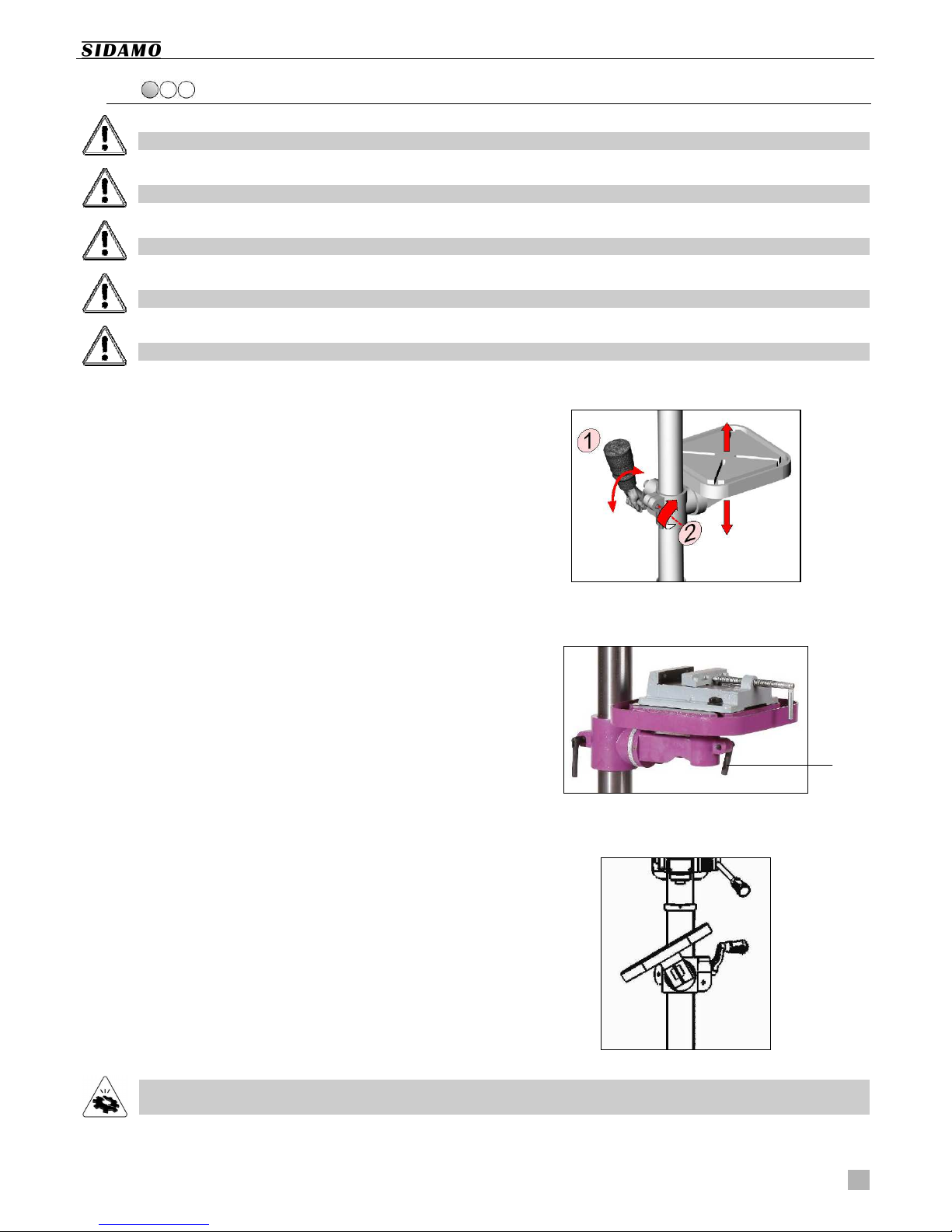
TABLE
TABLE TABLE
TABLE
Stop the machine before moving the table and the workpiece.
Stop the machine before moving the table and the workpiece.Stop the machine before moving the table and the workpiece.
Stop the machine before moving the table and the workpiece.
Never hold the workpiece with your hands. Always clamp it using a vice or clamps.
Never hold the workpiece with your hands. Always clamp it using a vice or clamps.Never hold the workpiece with your hands. Always clamp it using a vice or clamps.
Never hold the workpiece with your hands. Always clamp it using a vice or clamps.
Remove all objects from the table and remove the tool f
Remove all objects from the table and remove the tool fRemove all objects from the table and remove the tool f
Remove all objects from the table and remove the tool from the chuck, prior to any operation.
rom the chuck, prior to any operation.rom the chuck, prior to any operation.
rom the chuck, prior to any operation.
Mind the risk of pinching and crushing.
Mind the risk of pinching and crushing.Mind the risk of pinching and crushing.
Mind the risk of pinching and crushing.
Fix the vice of the workpiece to the table, using a set of clamps.
Fix the vice of the workpiece to the table, using a set of clamps.Fix the vice of the workpiece to the table, using a set of clamps.
Fix the vice of the workpiece to the table, using a set of clamps.
A.
A.A.
A.
To move the table up and down :
To move the table up and down :To move the table up and down :
To move the table up and down :
1. Untighten the locking handle of the support
sleeve of the table (2).
2. Rotate the handle to move the table (1) up or
down.
3. Tighten the locking handle of the support
sleeve of the table (2).
B.
B.B.
B.
To tilt the table :
To tilt the table :To tilt the table :
To tilt the table :
1. Untighten the locking handle of the table (3).
2. Tilt the table.
3. Tighten the locking handle of the table (3).
C.
C.C.
C.
To give an angle to the
To give an angle to theTo give an angle to the
To give an angle to the table :
table : table :
table :
1. Untighten the pivot bolt located under the
table.
2. Set the table to the angle required, using the
marking.
3. Tighten the pivot bolt.
To ensure a maximal safety when working, always firmly clam
To ensure a maximal safety when working, always firmly clamTo ensure a maximal safety when working, always firmly clam
To ensure a maximal safety when working, always firmly clamp the workpiece using a convenient clamping tool fixed to
p the workpiece using a convenient clamping tool fixed to p the workpiece using a convenient clamping tool fixed to
p the workpiece using a convenient clamping tool fixed to
the T slots of the table or into the vice.
the T slots of the table or into the vice.the T slots of the table or into the vice.
the T slots of the table or into the vice.
3

User’s manual PE22A
16
6.6.
6.6.6.6.
6.6.
ASSEMBLING AND DISM
ASSEMBLING AND DISM ASSEMBLING AND DISM
ASSEMBLING AND DISMANTLING T E TOOL
ANTLING T E TOOLANTLING T E TOOL
ANTLING T E TOOL
Stop the machine before any tool change.
Stop the machine before any tool change.Stop the machine before any tool change.
Stop the machine before any tool change.
Remove all objects from the table prior to any operation.
Remove all objects from the table prior to any operation.Remove all objects from the table prior to any operation.
Remove all objects from the table prior to any operation.
Mind t
Mind tMind t
Mind the risk of punching, pinching, prick, and crushing.
he risk of punching, pinching, prick, and crushing.he risk of punching, pinching, prick, and crushing.
he risk of punching, pinching, prick, and crushing.
Wear protective gloves.
Wear protective gloves.Wear protective gloves.
Wear protective gloves.
Use following tools :
CM2 - B18 shank of chuck with a self-clamping
chuck 1 to 16 mm - B18.
taper shank CM2.
I.
I.I.
I.
Assembling the tool :
Assembling the tool :Assembling the tool :
Assembling the tool :
1. Stop the machine.
2. Degrease the spindle and the shank of the chuck or
the taper part of the tool.
A. 1. Fit the shank of the chuck into the chuck.
2. Fit the assembly into the spindle.
3. Fit the cylindrical-shank tool Ø1 mm to Ø16
mm into the chuck.
B. 1. Directly fit the taper-shank tool into the
spindle (if necessary, adapt the size of the
morse taper, using a convenient adaptor).
II.
II.II.
II.
Dismantling the tool :
Dismantling the tool :Dismantling the tool :
Dismantling the tool :
1. Stop the machine.
2. Move the table up so it is 250 mm under the
accessory.
3. Move the spindle down, using the capstan wheel, on
about 100 mm.
4. Stop the spindle, so that it cannot move up, using
the drilling depth stop.
5. Rotate the spindle by hand until you can see the
shank of the chuck.
6. Fit a taper drift (A) into the port of the spindle (B).
7. Gently tap on the end on the taper drift, using a
mallet, to take the shank of the chuck or the taper
part of the tool out.
A
B

User’s manual PE22A
17
6.7.
6.7.6.7.
6.7.
SELECTING ROTATING S
SELECTING ROTATING SSELECTING ROTATING S
SELECTING ROTATING SPEEDS OF T E SPINDLE
PEEDS OF T E SPINDLEPEEDS OF T E SPINDLE
PEEDS OF T E SPINDLE
Stop the machine before selecting a gear.
Stop the machine before selecting a gear.Stop the machine before selecting a gear.
Stop the machine before selecting a gear.
Mind the risk of entanglement or winding.
Mind the risk of entanglement or winding.Mind the risk of entanglement or winding.
Mind the risk of entanglement or winding.
A safety grip micro switch prevents the machine from
starting in case the belt cover is opened.
To select a rotating speed for the spindle :
1. Stop the machine.
2. Remove the screw of the belt cover to open it.
3. Unlock the motor by untightening the three
tensioning nuts of the motor (A).
4. Rotate the tension knob of belts (B) to release the
belts and change the position of belts, according to
following table (see next page), to get the speed
required.
5. Tension the belts and lock the motor in this
position, using the three tensioning screws of the
motor.
6. To make sure the tension of the belt is correct, the
deflection must be about 13 mm when a 5 kg
pressure is applied.
7. Close the belt cover.
Perform the change of spindle speed, when
Perform the change of spindle speed, whenPerform the change of spindle speed, when
Perform the change of spindle speed, when the spindle is on its higher position.
the spindle is on its higher position. the spindle is on its higher position.
the spindle is on its higher position.
A
B
User’s manual PE22A
18
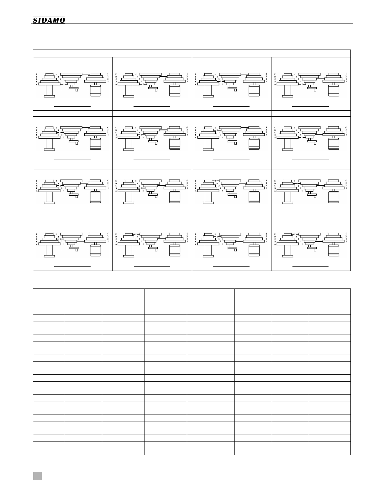
To the rotating speed, change the position of the belts on
the driving pulleys.
Please refer to the speed table fixed into the belt cover.
SPEEDS IN RPM ACCORDING TO T E TRANSMISSION RATIO
SPEEDS IN RPM ACCORDING TO T E TRANSMISSION RATIOSPEEDS IN RPM ACCORDING TO T E TRANSMISSION RATIO
SPEEDS IN RPM ACCORDING TO T E TRANSMISSION RATIO
1
11
1
2
22
2
3
33
3
4
44
4
180 rpm
180 rpm180 rpm
180 rpm
270 rpm
270 rpm270 rpm
270 rpm
310 rpm
310 rpm310 rpm
310 rpm
420 rpm
420 rpm420 rpm
420 rpm
BELTS : A–1 . 5–4
BELTS : A–1 . 4–3 BELTS : B–2 . 5–4 BELTS : A–1 . 3–2
5
55
5
6
66
6
7
77
7
8
88
8
430 rpm
430 rpm430 rpm
430 rpm
470 rpm
470 rpm470 rpm
470 rpm
580 rpm
580 rpm580 rpm
580 rpm
630 rpm
630 rpm630 rpm
630 rpm
BELTS : C–3 . 5–4
BELTS : B–2 . 4–3 BELTS : D–4 . 5–4 BELTS : A–1 . 2–1
9
99
9
10
1010
10
11
1111
11
12
1212
12
650 rpm
650 rpm650 rpm
650 rpm
720 rpm
720 rpm720 rpm
720 rpm
1230 rpm
1230 rpm1230 rpm
1230 rpm
1320 rpm
1320 rpm1320 rpm
1320 rpm
BELTS : C–3 . 4–3
BELTS : B–2 . 3–2 BELTS : E–5 . 4–3 BELTS : D–4 . 3–2
13
1313
13
14
1414
14
15
1515
15
16
1616
16
1460 rpm
1460 rpm1460 rpm
1460 rpm
1880 rpm
1880 rpm1880 rpm
1880 rpm
1950 rpm
1950 rpm1950 rpm
1950 rpm
2770 rpm
2770 rpm2770 rpm
2770 rpm
BELTS : C–3 . 2–1
BELTS : E–5 . 3–2 BELTS : D–4 . 2–1 BELTS : E–5 . 2–1
TABLE OF RECOMMENDED SPEEDS, IN RELATION WIT MATERIALS AND DRILL DIAMETERS
Diameter
DiameterDiameter
Diameter
Steel
SteelSteel
Steel
30 to 40
30 to 4030 to 40
30 to 40
kg/mm²
kg/mm²kg/mm²
kg/mm²
Steel
SteelSteel
Steel
50 to 70
50 to 7050 to 70
50 to 70
kg/mm²
kg/mm²kg/mm²
kg/mm²
Steel
SteelSteel
Steel
80 to 90
80 to 9080 to 90
80 to 90
kg/mm²
kg/mm²kg/mm²
kg/mm²
Allied steel
Allied steelAllied steel
Allied steel
140 to 180
140 to 180140 to 180
140 to 180
kg/mm²
kg/mm²kg/mm²
kg/mm²
Cast iron
Cast ironCast iron
Cast iron
Brass
BrassBrass
Brass
Al
AlAl
Aluminium
uminiumuminium
uminium
35
3535
35
248 181 105 76 171 457 1 190
34
3434
34
255 186 108 78 176 471 1 225
32
3232
32
271 198 115 83 188 500 1 302
30
3030
30
289 211 122 89 200 533 1 389
28
2828
28
310 226 131 95 214 571 1 488
25
2525
25
347 253 147 107 240 640 1 667
22
2222
22
394 288 167 121 273 727 1 894
20
2020
20
433 317 183 133 300 800 2 083
18
1818
18
481 352 204 148 333 889 2 315
16
1616
16
542 396 229 167 375 1 000 2 604
14
1414
14
619 452 262 190 429 1 143 2 976
13
1313
13
667 487 282 205 462 1 231 3 205
12
1212
12
722 528 306 222 500 1 333 3 472
11
1111
11
788 576 333 242 545 1 455 3 788
10
1010
10
867 633 367 267 600 1 600 4 167
9
99
9
963 704 407 296 667 1 778 4 630
8
88
8
1 083 792 458 333 750 2 000 5 208
7
77
7
1 238 905 524 381 857 2 286 5 952
6
66
6
1 444 1 056 611 444 1 000 2 667 6 944
5
55
5
1 733 1 267 733 533 1 200 3 200 8 333
4
44
4
2 167 1 583 917 667 1 500 4 000 10 417
3
33
3
2 889 2 111 1 222 889 2 000 5 333 13 889

User’s manual PE22A
19
6.8.
6.8.6.8.
6.8.
LASER DEVICE
LASER DEVICE LASER DEVICE
LASER DEVICE
Switch off the machine prior to opening the battery housing.
Switch off the machine prior to opening the battery housing.Switch off the machine prior to opening the battery housing.
Switch off the machine prior to opening the battery housing.
Do not open the battery housing when the machine is running.
Do not open the battery housing when the machine is running.Do not open the battery housing when the machine is running.
Do not open the battery housing when the machine is running.
The drilling machine PE22A is equipped with a Class 2 laser
device, to position the drilling :
1. Insert two batteries (type AAA R03 1.5V) into the
housing located opposite to the switch. Respect
polarities.
2. Press the « I » position of the switch (A) to start the
laser device.
3. Adjust the laser device, using both knobs (B) to
correctly position the drilling, the table and the
workpiece.
4. Do not move the table to not change the
position of the drilling.
Use only AAA R03 1.5V type batteries.
Use only AAA R03 1.5V type batteries.Use only AAA R03 1.5V type batteries.
Use only AAA R03 1.5V type batteries.
Do not attempt to charge the batteries supplied with the machine.
Do not attempt to charge the batteries supplied with the machine.Do not attempt to charge the batteries supplied with the machine.
Do not attempt to charge the batteries supplied with the machine.
Remove batteries from the housing in case they are not used for a long period of time.
Remove batteries from the housing in case they are not used for a long period of time.Remove batteries from the housing in case they are not used for a long period of time.
Remove batteries from the housing in case they are not used for a long period of time.
Replace all batteries at the same time.
Replace all batteries at the same time.Replace all batteries at the same time.
Replace all batteries at the same time.
In case batteries are damaged or in case of improper use of batteries, some corrosive liquid can be expelled and some
In case batteries are damaged or in case of improper use of batteries, some corrosive liquid can be expelled and some In case batteries are damaged or in case of improper use of batteries, some corrosive liquid can be expelled and some
In case batteries are damaged or in case of improper use of batteries, some corrosive liquid can be expelled and some
fumes
fumesfumes
fumes can come out : avoid any contact with the hands, the skin and the eyes (this liquid can cause
can come out : avoid any contact with the hands, the skin and the eyes (this liquid can cause can come out : avoid any contact with the hands, the skin and the eyes (this liquid can cause
can come out : avoid any contact with the hands, the skin and the eyes (this liquid can cause irritations or burns
irritations or burns irritations or burns
irritations or burns
and is poisonous when ingested) and ventilate the working place (the fumes can cause
and is poisonous when ingested) and ventilate the working place (the fumes can cause and is poisonous when ingested) and ventilate the working place (the fumes can cause
and is poisonous when ingested) and ventilate the working place (the fumes can cause irritations of airways). In case of
irritations of airways). In case of irritations of airways). In case of
irritations of airways). In case of
accidental contact,
accidental contact,accidental contact,
accidental contact, wash using water and/or in case of unease, contact a doctor.
wash using water and/or in case of unease, contact a doctor. wash using water and/or in case of unease, contact a doctor.
wash using water and/or in case of unease, contact a doctor.
Do not dispose of batteries in a fire (risk of explosion) or in a dustbin.
Do not dispose of batteries in a fire (risk of explosion) or in a dustbin.Do not dispose of batteries in a fire (risk of explosion) or in a dustbin.
Do not dispose of batteries in a fire (risk of explosion) or in a dustbin.
According to the European Directive 2006/66/CE, used or defective batteries must be put apart and recycled,
According to the European Directive 2006/66/CE, used or defective batteries must be put apart and recycled, According to the European Directive 2006/66/CE, used or defective batteries must be put apart and recycled,
According to the European Directive 2006/66/CE, used or defective batteries must be put apart and recycled,
following
followingfollowing
following a convenient process.
a convenient process. a convenient process.
a convenient process.
6.9.
6.9.6.9.
6.9.
DIGITAL DISPLAY
DIGITAL DISPLAY DIGITAL DISPLAY
DIGITAL DISPLAY
The drilling machine PE22A is equipped with a digital display
for the drilling depth, with a tolerance of +/- 5 mm :
There are three keys to operate the display :
A. Switching on the digital display.
B. Selection of the unit, for distances : « inch » and
« mm » (millimetre).
C. Stetting the spindle stroke to zero.
A
B
C
A
B

User’s manual PE22A
20
6.10.
6.10.6.10.
6.10.
DRILLING PROCEDURE
DRILLING PROCEDURE DRILLING PROCEDURE
DRILLING PROCEDURE
Always wear adapted personal protective equipments.
Always wear adapted personal protective equipments.Always wear adapted personal protective equipments.
Always wear adapted personal protective equipments.
All operations relating to drilling must be performed when the s
All operations relating to drilling must be performed when the sAll operations relating to drilling must be performed when the s
All operations relating to drilling must be performed when the spindle is on its up position. The drill must show no
pindle is on its up position. The drill must show no pindle is on its up position. The drill must show no
pindle is on its up position. The drill must show no
evidence of rotation.
evidence of rotation.evidence of rotation.
evidence of rotation.
Always keep your hands away from the drilling area when the machine is operated.
Always keep your hands away from the drilling area when the machine is operated.Always keep your hands away from the drilling area when the machine is operated.
Always keep your hands away from the drilling area when the machine is operated.
Always switch off the machine prior to performing any positioning of a workpiece or removal of chi
Always switch off the machine prior to performing any positioning of a workpiece or removal of chiAlways switch off the machine prior to performing any positioning of a workpiece or removal of chi
Always switch off the machine prior to performing any positioning of a workpiece or removal of chips.
ps.ps.
ps.
Never hold work pieces with your hands. Carefully clamp them using convenient a tooling, such as a vice or clamps.
Never hold work pieces with your hands. Carefully clamp them using convenient a tooling, such as a vice or clamps.Never hold work pieces with your hands. Carefully clamp them using convenient a tooling, such as a vice or clamps.
Never hold work pieces with your hands. Carefully clamp them using convenient a tooling, such as a vice or clamps.
Operating cycle
Operating cycleOperating cycle
Operating cycle
Drilling instructions :
1. The drill should be perfectly sharpened and
clamped. The workpiece should be firmly clamped
on the table or in the vice.
2. Adjust the height of the working table.
3. Properly adjust the protective shield of the chuck,
by positioning the pin (a safety micro switch is used
to closing) and tighten the screw.
4. Make sure the rotating speed of the spindle is in
relation with the type of work to do.
5. Adjust the depth-drilling stop.
6. Adjust the light, is necessary.
7. Switch on the laser device and adjust it, if
necessary.
8. Press the green start button « I » to start the
drilling machine (close the cover of the control box,
but do not lock it).
9. Start drilling. Gently apply a moderate pressure on
the capstan wheel.
Stopping :
1. Press the red stop button « 0 » to stop the drilling
machine.
2. Switch off the laser device.
3. Switch off the light.
4. Open the protective shield of the chuck.
When the drilling is finished, release the capstan wheel and gently move the spindle back (dead centre, upwards).
When the drilling is finished, release the capstan wheel and gently move the spindle back (dead centre, upwards).When the drilling is finished, release the capstan wheel and gently move the spindle back (dead centre, upwards).
When the drilling is finished, release the capstan wheel and gently move the spindle back (dead centre, upwards).
6.11.
6.11.6.11.
6.11.
STORING T E MAC INE
STORING T E MAC INE STORING T E MAC INE
STORING T E MAC INE W EN IT IS NOT USED
W EN IT IS NOT USED W EN IT IS NOT USED
W EN IT IS NOT USED
If the drilling machine is not used for a long time, please
follow below instructions :
1. Unplug the machine from the main socket.
2. Remove the batteries from the laser device.
3. Remove all objects from the table and remove the
tool from the chuck.
4. Release the return spring.
5. Carefully clean and oil the machine.
6. Cover the machine, if necessary.
Table of contents


