Sidewinder 105C User manual
OWNER’S MANUAL
ROTARY SURFACE CLEANER
Models 105C, 105F, 105CW, & 105FW
Revision 2.01

1
ROTARY SURFACE CLEANER
WARNING
HIGH PRESSURE CAN CAUSE SERIOUS INJURY,
MAXIMUM WORKING PRESSURE IS
4000 P.S.I.
Any fluid under high pressure, from spray or leaks, can penetrate the skin and cause serious tissue
damage. Therefore, extreme caution must be exercised when using any high pressure equipment.
If you are injured, see a physician immediately. DO NOT TREAT AS A SIMPLE CUT
OPERATING PRECAUTIONS
1. Handle the cleaning unit carefully. Never point the rotating nozzles at yourself or
anyone else.
2. Never permit any part of your body to come in contact with the fluid stream.
Never attempt to remove nozzles, disassemble or repair equipment without first doing the
following:
a. Shut off pressure washer engine or electric motor
b. Squeeze trigger gun to release pressure between the pressure washer and the surface
cleaner.
c. Disconnect the hose from the surface cleaner.
d. Remove nozzles or disassemble as required.
1. Inspect and tighten all fluid connections before use. Never exceed 4000 P.S.I.
2. Never attempt to plug a hose leak with any part of your body, adhesive tape or any other
makeshift device. Do not attempt to repair a spray hose, replace it instead.
3. Always wear protective eye ware and foot ware while operating the surface cleaner.
4. Never attempt to alter or modify any part of this equipment; doing so could result in a system
malfunction, injury, and void the warranty.
5. Never leave equipment unattended. Keep unit away from children, pets, or anyone not familiar
with high pressure cleaning equipment.
6. Never begin to use equipment without clearing debris from the area to be cleaned.
7. Never attempt to use equipment without adequate lighting.
8. Never attempt to clean objects or surfaces that protrude from surface.
9. Always operate cleaning unit at a safe rate of speed.
10.Never tie off trigger gun. Serious injury could result if the unit should malfunction. Always
operate the unit with sure footing, never over-reaching.
11.Never run chemicals through cleaning unit. This may result in a premature system failure and
will void warranties.

2
EQUIPMENT MAINTENANCE
1. Inspect unit daily.
2. Avoid unit abuse and neglect.
3. Tighten rotating bar, bolts, and fittings as needed during daily inspection.
4. Check for leaks and repair as required.
5. Check for water streaming from the swivel by-pass ports; some leaking is normal (see
troubleshooting below)
REQUIRED TOOLS
1. Check with distributor for repair kits and all necessary repair tools.
2. Tools required: Allen wrench, 5/8” open end wrench, snap ring pliers, flathead screw driver,
hammer, and vice grips.
TROUBLE SHOOTING
TROUBLE CAUSE SOLUTION
Insufficient pressure Pressure set too low Increase pressure
Plugged nozzle Clean or replace
Nozzle worn Replace nozzle
Incorrect nozzle size Change nozzle
Excessive vibration Clogged Nozzle Clean or replace
Rotating bar bent Replace
Swivel shaft bent Replace
Spray bar doesn’t spin Seal malfunction Replace
Bearing failure Replace
Snap ring dislodge Reinsert snap ring
Seal has drag Allow break-in
Streaking pattern Clogged Nozzle Clean or replace
Water flowing from Seal is worn Replace Seal;
swivel by-pass ports Replace rear shaft if
required.
OPERATING PRESSURE AND FLOW
The Rotary Surface Cleaner will operate at a minimum flow of 3.5 gpm @ 2000 psi and a
maximum flow of 12 gpm @ 4000 psi.
To determine your pressure washer’s flow rate and pressure, refer to your operating manual.

3
NOZZLES
Determine what size nozzle orifice your pressure cleaning system has. The best way to determine
nozzle orifice is by looking at the original nozzles recommended with your cleaning system.
EXAMPLE: Nozzle reads 2503 Power Nozzle
25 Indicates nozzle spray pattern.
03 Indicates nozzle orifice size.
When installing nozzles make sure that “V” grove in the nozzle is parallel to rotating bar; note
orientation prior to removal.
SEAL REMOVAL
1. Remove the four socket head cap bolts from the top of the swivel.
2. Remove the swivel rear shaft.
3. Remove the internal retaining ring.
4. Remove the back-up spacer.
5. Remove the seal using a flat-head screw driver to pry out seal. Do NOT scratch the walls of the
seal housing.
SEAL REPLACEMENT
1. Apply oil to outer surface of the new seal along the O-ring
2. Insert the seal into seal housing. Make sure that the “U-CUP” portion of the seal is facing
downward.
3. Position the seal and then lower into seal housing.
4. Press the seal to bottom of seal housing by hand. Keep seal as level as possible. Avoid seal
misalignment, this could result in premature seal failure.
5. Re-insert the back-up spacer. Make sure that the seal and back-up spacer are seated properly to
allow for the installation of the retainer ring.
6. Install the internal retaining ring. Make sure that the flat surface of the retainer ring is facing
up. If the rounded surface is facing up, the retaining ring may unseat itself from its grove when
pressure is introduced to the swivel. Also, make sure that the retaining ring expands into its
grove. A mistreated or bent retaining ring will result in swivel failure.
7. Apply a thin layer of grease the rear shaft and gently but firmly press the shaft into the seal.
Keep the rear shaft as straight as possible to avoid damaging the seal.
8. Re-install swivel rear shaft bolts.
See Figure 5 for a diagram of swivel components.

4
TESTING SWIVEL REPAIR
1. Connect all hose and fittings according to the manufacturer’s instructions.
2. Start the pressure washer and send high pressure water through swivel.
3. Allow the spray bar to spin for a period of 3-5 minutes during break-in period. During this
period, the seal will seat itself.
TROUBLE SHOOTING REPAIR PROCEDURE
TROUBLE SOLUTION
Swivel head will not come off. Install a 1/4” N.P.T. male plug into the swivel inlet. Then
insert a long Phillips-head screwdriver into swivel outlet and
gently tap screw driver head with hammer and remove
swivel head.
Bronze back-up spacer will not Invert swivel and gently tap
come out of housing on swivel outlet
. side or use an EZ Out tapping device to tap into bronze ring.
(If back-up spacer is damaged during removal it is
recommended to replace it).
Sparybar will not spin Make sure internal retaining ring is installed.
NOTE: Do not allow the Rotary Surface Cleaner to go into a vibrating motion induced by
excessive RPMs. If you experience excessive vibration, consult the factory.
NEVER RUN CHEMICALS THROUGH THE SWIVEL!
The swivel is intended to handle water only (cold or hot) maximum temperature = 212; F. Pressure
rating is limited to a maximum of 4000 P.S.I. @ 12 gpm and 2000 RPM.
5
Figure 1
(105C & 105F Models)

6
Figure 2
(105CW & 105FW Models)
7
Figure 3
(105C & 105CW Models)

8
Figure 4
(105F and 105FW Models

9
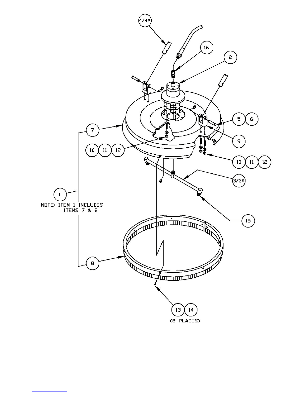
Figure 5
(All Models)

10
Parts List
Model # and Quantity
Item P/N Description 105C 105F 105CW 105FW
151000 Cover Assembly - - - -
252000 Model 105 Swivel Assembly - - - -
353200 Fixed Spraybar Assy. (with nozzles) - - - -
3A 53300 Fixed Spraybar Assy. (without nozzles) - - - -
454000 Collapsible Handle Assembly - - - -
4A 54100 Fixed Handle Assembly - - - -
551001 Handle Hinge Pin 2 2 2 2
651002 E - Clip 2 2 2 2
751003 Cover (Specify Color) 1 1 1 1
851004 Brush Assembly 1 1 - -
8A 51032 Brush Assembly, Wheel - - 1 1
951005 Lower Handle Hinge Bracket 2 2 2 2
10 21125-07 1/4-20 x 1 1/4" S. H. Set Screw, S.S. 10 10 10 10
11 21725 1/4-20 Flat Washer, S.S. 10 10 10 10
12 21525 1/4-20 Hex Nut with Nylon Insert, S.S. 12 13 12 13
13 21220-04 10-24 x 3/4" S.H. Cap Screw, S.S. 8 8 8 8
14 21520 10-24 Hex Nut with Nylon Insert, S.S. 8 8 8 8
15 25030 Nozzle (standard) 2 2 2 2
16 31802 1/4” Male x Female Swivel Adapter 1 1 1 1
17 51006 Outer Low Pressure Seal 1 1 1 1
18 51007 105 Swivel Housing 1 1 1 1
19 51008 Bearing 2 2 2 2
20 51009 Internal Retaining Ring, Bearing 1 1 1 1
21 51010 Inner Low Pressure Seal 1 1 1 1
22 51011 External Retaining Ring, Bearing Shaft 1 1 1 1
23 51012 105 Bearing Shaft 1 1 1 1
24 51013 TFE Swivel Seal with O-Ring 1 1 1 1
25 51014 Back-Up Spacer 1 1 1 1
26 51015 Internal Retaining Ring, Swivel Seal 1 1 1 1
27 23000 Swivel Repair Kit N/A N/A N/A N/A
28 51016 Rear Shaft Assembly 1 1 1 1
29 21220-05 10-24 x 7/8" S.H. Cap Screw, S.S. 4 4 4 4
30 51017 Rubber Hand Grip, Fixed - 1 - 1
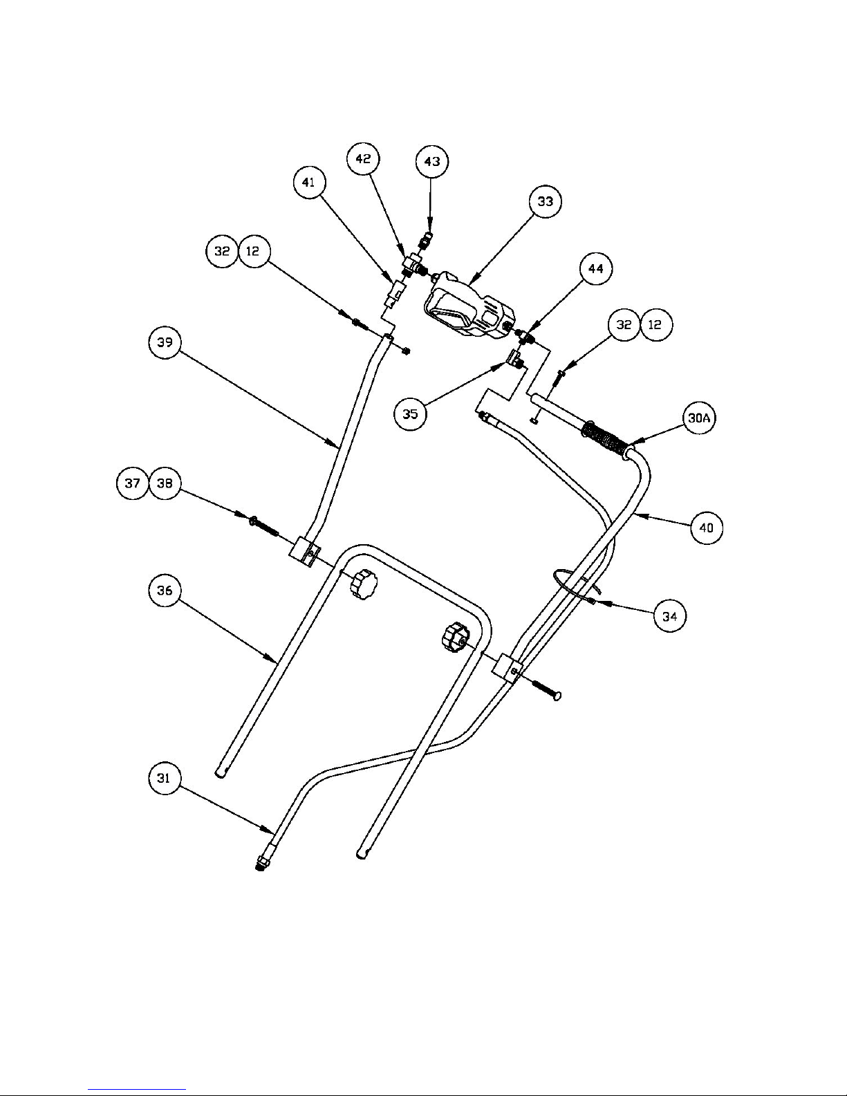
30A 51033 Rubber Hand Grip, Collapsible 1 - 1 -
31 51020 61" High Pressure Hose 1 1 1 1
32 21325-07 1/4-20 x 1 1/4" Hex Head Bolt, S.S. 2 1 2 1

11
Parts List
Model # and Quantity
Item P/N Description 105C 105F 105CW 105FW
33 51024 Trigger 1 1 1 1
34 51019 Tie Wrap 1 - 1 -
35 31702 1/4 90 Degree Female Swivel Fitting 1 1 1 1
36 51021 Lower Handle Tube Assembly 1 - 1 -
37 21430-12 5/16-18 x 2 1/2" Carriage Bolt, S.S. 2 - 2 -
38 21830 5/16-18 Hand Knob 2 - 2 -
39 51022 Upper Handle Tube, Right 1 - 1 -
40 51018 Upper Handle Tube, Left 1 - 1 -
41 51023 Handle Extension Plug 1 - 1 -
42 31403 3/8F x 3/8M x 3/8M Branch Tee 1 - 1 -
43 31503 3/8" Male Quick Disconnect 1 1 1 1
44 31602 1/4M x 1/4M x 1/4M Tee 1 1 1 1
45 51026 Handle Tube, Right - 1 - 1
46 51029 Handle Tube, Left - 1 - 1
47 51028 Handle Clamp - 4 - 4
48 21325-10 1/4-20 x 2" Hex Head Bolt, S.S. - 2 - 2
49 51027 Hose Clamp - 2 - 2
50 51030 Wheel Tab - - 4 4
51 51031 Caster Wheel - - 4 4
52 21922-01 10-32 x 3/8" Long, Flat Head, S.S. - - 24 24
53 22022 10-32 External Tooth Hex Nut, S.S. - - 16 16
HYDRAMOTION CLEANING SYSTEMS
401 E. Fourth Street, Building 20, Bridgeport, PA 19405
Phone: 800-726-1526 •Fax: 610-239-7863
This manual suits for next models
3
Table of contents


