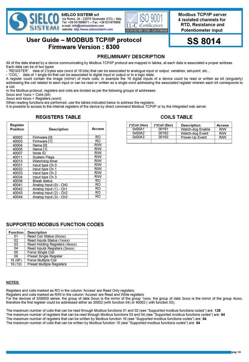
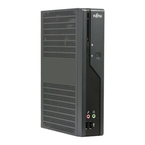
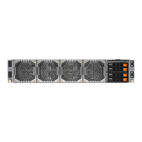
SIELCO SISTEM SS 8148 User manual

SIELCO SISTEMI srl
via Roma, 24 - 22070 Guanzate (CO) – Italy
Tel: +3 0318 671 – Fax: +3 031 76 66
e-mail: info@sielcosistemi.com
website: http://www.sielcosistemi.com
TECHNICAL SPECIFICATIONS (Typical @ 25 °C and in th nominal conditions)
SS 8148
SS 8148
FEATURES
- Int rfac Eth rn t 10/100 Bas -T, Modbus TCP S rv r
- N.16 Digital inputs
- Built-in W b s rv r to acquir th digital inputs stat via w b brows r
- R mot ly programmabl
- Conn ction by r movabl scr w-t rminals
- LED signalling for Link/Act Eth rn t, pow r supply
- LED signalling for digital inputs stat
- Galvanic isolation on all th ways
- EMC compliant – CE mark
- In complianc to EN-50022 DIN rail mounting
GENERAL DESCRIPTION
The device SS8148 is a Modbus TCP server unit with 16 digital input channels.
For the digital inputs are available up to 4 counters at 32 bit with measure of frequency up to 300 Hz.
The Ethernet interface allows to read and write in real time the value of device's internal registers.
The built-in Web Server of SS8148 allows the remote visualization and acquisition of the digital inputs state and access to and configure the main
Ethernet parameters via web browser.
The device SS8148 realizes a full electrical isolation between the lines, introducing a valid protection against the effects of all ground loops eventually
existing in industrial applications.
The LEDs of signalling of Ethernet activity, input and power supply allow a direct monitoring of the system functionality.
The connection is made by removable screw-terminals (inputs and power supply) and RJ45 plug (Ethernet).
The device is housed in a rough self-extinguishing plastic enclosure which, thanks to its thin profile of 22.5 mm only, allows a high density mounting on
EN-50022 standard DIN rail.
Modbus TCP/IP s rv r
16 Digital Inputs
In complianc with Eth rn t IEEE 802.3
N twork int rfac Ethernet 10/100Base-T
Protocol Modbus TCP
Max. cable length 100 meters
Channels 16
Input voltage (bipolar)
OFF state 0 ÷ 3 V
ON state 10 ÷ 30 V
Impedance 4.7 KW
Sample time 5 ms
Number of counters 4
Counters register bit-length 32 bit
Counters frequency up to 300 Hz
Minimum pulse width 1 ms
Digital Inputs Pow r supply 10 ÷ 30 Vdc
Current consumption 60 mA typ @24 Vdc(standby)
140 mA max @24Vdc
230 mA max
Isolations
Power supply / Ethernet 1500 Vac, 50 Hz, 1 min.
Inputs / Ethernet 1500 Vac, 50 Hz, 1 min.
Inputs 0÷7/ Inputs 8÷15 1500 Vac, 50 Hz, 1 min.
Inputs / Power supply 1500 Vac, 50 Hz, 1 min.
T mp ratur & Humidity
Operative temperature -10 ÷ +60 °C
Storage temperature -40 ÷ +85 °C
Relative humidity (not cond.) 0 ÷ 0 %
Conn ctions
Ethernet RJ-45 (on terminals side)
Inputs / Supply Removable screw terminals
Housing
Material Self-extinguishing plastic
Mounting DIN rail EN-50022
Dimensions in mm.(WxHxT) 100 x 120 x 22.5
Weight about 160 gr.
EMC ( for industrial nvironm nts )
Immunity EN 61000-6-2
Emission EN 61000-6-4

Sielco Sistemi s.r.l. reserves its right to modify the characteristics of its products totally or in part without warning at any time.
ED.03.16 REV.00
CONNECTIONS
POWER SUPPLY
+
-
10÷30 Vdc
O
P-V
+V
INIT
ON: short-circuit
to GND
Q
PV-
INIT
DIGITAL INPUTS
MECHANICAL DIMENSIONS (mm)
120
22.5
100
“ SS 8148 “
Note: the device is provided with default configuration as:
IP address: 1 2.168.1.100
Modbus address: 1
HOW TO ORDER
NOTES:
th input chann ls from 0 to 7 ar not isolat d b tw n th m .
th input chann ls from 8 to 15 ar not isolat d b tw n th m .
Th group of input chann ls 0÷7 is isolat d from th group of input chann ls 8÷15.
F
E
DI0
G
H
I
DI1
DI2
DI3
J
E
DI4
L
M
N
DI5
DI6
DI7
COM COM
2
1
DI8
3
4
5
DI9
DI10
DI11
6
1
DI12
7
8
9
DI13
DI14
DI15
COM1 COM1
GROUP DIGITAL INPUTS 0÷7
GROUP DIGITAL INPUTS 8÷15
INSTALLATION INSTRUCTIONS
The device is suitable for fitting to DIN rails in the vertical position.
It is always a good thing to space the devices together 5mm. Make sure that sufficient air
air flow is provided for the device avoiding to place raceways or other objects which could
obstruct the ventilation slits. Moreover it is suggested to avoid that devices are mounted
above appliances generating heat. Install the device in a place without vibrations. It is
also suggested to avoid routing conductors near power signal cables and to use shielded
cables for connecting signals.
MODULE CONFIGURATION
To configure the SS8000 series devices, it is necessary to enable the INIT mode. This
mode allows you to access the device with the following default parameters :
IP Addr ss:192.168.1.174 (DHCP disabled), or IP provided by DHCP (if enabled)
Modbus Addr ss: 245
To enter the INIT mode follow these steps:
- Turn off the device;
- Connect the INIT terminal to the -V terminal as shown in figure.
- Turn on the device and connect with an internet browser to the device using the default
parameters listed above and using the default login credentials:
Us rnam : admin
Password: admin
To exit INIT mode follow these steps:
- Turn off the device;
- Remove the INIT connection;
- Turn on the device and connect with the new parameters.
RESET FUNCTION- “P” BUTTON
If it is necessary to restore the default device parameters, with device powered and not in
INIT condition, push the front located “P” button for at least 5 seconds.
The green led PWR will switch-off, the yellow led STS will become orange and the reset
of the device will occur. When the reset procedure will be finished, both the leds will set
back to the default condition and the following parameters will be loaded :
Ethernet: Username: admin
- IP Address: 1 2.168.1.100 Password: admin
- Subnet Mask : 255.255.255.0
- Gateway Mask: 1 2.168.1.1 Modbus Address: 1
Device not powered
LIGHT SIGNALLING
LED COLOUR STATE DESCRIPTION
PWR GREEN ON
OFF
Device powered
STS YELLOW OFF Device in RUN modality
ON Digital Inputs High Level (1)I n RED
OFF Digital Inputs Low Level (0)
BLINK Device in INIT modality
BLINK Watchdog alarm
MAPPATURA REGISTRI MODBUS
R gist r
Position
Winlog
Syntax D scription Acc ss
40007 3:06 Node ID R/W
40011 3:10 System Flags R/W
40013 3:12 Watchdog timer R/W
40032 3:31 Digital Inputs RO
40033 3:32 Digital Inputs Rise Latch R/W
40034 3:33 Digital Inputs Fall Latch R/W
40035 3:34 Freq. Digital Input 0 RO
40036 3:35 Freq. Digital Input 1 RO
40037 3:36 Freq. Digital Input 2 RO
40038 3:37 Freq. Digital Input 3 RO
4003 35:38 32 bit Counter Digital Input 0 R/W
40041 35:40 32 bit Counter Digital Input 1 R/W
40043 35:42 32 bit Counter Digital Input 2 R/W
40045 35:44 32 bit Counter Digital Input 3 R/W
Other SIELCO SISTEM Server manuals
Popular Server manuals by other brands

Dell
Dell PowerEdge C410X Getting started manual
Gigabyte
Gigabyte E283-S90-AAD1 user manual
Tektronix
Tektronix IntelliFrame VX14 A Series instruction manual
Digital Equipment
Digital Equipment DECserver 700 Hardware Installation Card
Cisco
Cisco APIC M3 Installation and service guide

Red Hat
Red Hat SATELLITE 5.3.0 RELEASE NOTES release note
