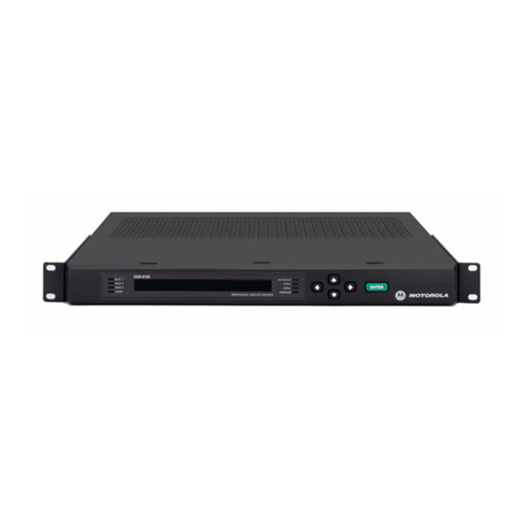
sielco RTX19/1 Operating instructions

Rev. 1.4 - 02/17
SIELCO srl - Via Toscana, 57/59 - 20090 BUCCINASCO (Mi) - ITALY - tel. 02 - 45713300 - www.sielco.org
RTX19/1
FM BROADCAST RECEIVER
87.5 ÷ 108 MHz
USER AND MAINTENANCE MANUAL

SIELCO srl - Via Toscana, 57/59 - 20090 BUCCINASCO (Mi) - ITALY - tel. 02 - 45713300 - www.sielco.org
RTX19/1 - USER & MAINTENANCE MANUAL - rev.1.4 - 02/17
Page 2
CONTENTS
1R&TTE DECLARATION OF CONFORMITY (DoC)......................................................... 3
2INTRODUCTION ................................................................................................................... 4
3GENERAL DESCRIPTION ................................................................................................... 5
4TECHNICALFEATURES ...................................................................................................... 6
4.1 FRONT VIEW ................................................................................................................... 6
4.2 REAR VIEW ...................................................................................................................... 7
4.3 TECHNICAL SPECIFICATIONS .................................................................................... 8
5REMOTE CONTROL FUNCTIONS .................................................................................... 9
6STL MANAGING FIRMWARE.......................................................................................... 10
6.1 INTRODUCTION ....................................................................................................... 10
6.2 PASSWORD ORGANISATION ................................................................................ 11
6.3 FACTORY DEFAULTPASSWORDS ....................................................................... 12
6.4 MENU AND COMMANDS DESCRIPTION .......................................................... 13
6.5 RECEIVER MENU .................................................................................................... 14
6.6 FACTORY MENU ...................................................................................................... 25
7SERVICE AND MAINTENANCE ...................................................................................... 26
8GUARANTEE ........................................................................................................................ 26
9SERVICE MANUAL............................................................................................................. 27
9.1 RECEIVER INTERNAL DESCRIPTION ................................................................ 27
9.2 RECEIVER INTERNAL MODULES & ELECTRICAL DIAGRAMS ................. 29

SIELCO srl - Via Toscana, 57/59 - 20090 BUCCINASCO (Mi) - ITALY - tel. 02 - 45713300 - www.sielco.org
RTX19/1 - USER & MAINTENANCE MANUAL - rev.1.4 - 02/17
Page 3
EU Declaration of Conformity (DoC)
Prot. 16/106/2016
We
SIELCO s.r.l
via Toscana 59
20090 - BUCCINASCO (MILANO) - ITALIA
declare that the DoC is issued under our sole responsibility and belongs to the following products:
RTX19/1 and RTX18B/1, FM Broadcast receiver
The object of the declaration described above is in conformity with the relevant Union harmonisation
legislation:
EMCDirective 2014/30/EU
LowVoltage Directive 2014/35/EU
RoHSDirective 2011/65/EU
The following harmonised standards and technical specifications have been applied:
Title,dateofstandard/specification:
EN 301 489-1 V1.9.2 ElectromagneticcompatibilityandRadiospectrumMatter
EN 60215: 1989+A1 : 1992+A2 : 1994 Safetyrequirements for radio transmitting equipment
EN 50581: 2012 Technicaldocumentationforthe assessment of electrical
and electronic products with respect to the restriction of
hazardoussubstances
Notified body (where applicable) notinvolved
Signed for and on behalf of:
Placeof issue: Date of issue (yyyy/mm/dd) Name,function,signature
Buccinasco- Italy 2016/05/05 ing. Salvatore Cosentino
SIELCOtechnical Manager

SIELCO srl - Via Toscana, 57/59 - 20090 BUCCINASCO (Mi) - ITALY - tel. 02 - 45713300 - www.sielco.org
RTX19/1 - USER & MAINTENANCE MANUAL - rev.1.4 - 02/17
Page 4
RTX19/1
FM BROADCAST RECEIVER
87.5 ÷ 108 MHz
INTRODUCTION
TheRTX19/1 Receiver isthe latestresult of theexperience gainedby SIELCO(formerly SIEL)during
years of producing FM broadcast equipment, transmitters, stl and stereo encoders.
This Receiver is specifically designed to be used in the harsh and noisy environment of a broadcast site
discriminatingweeksignalsinacrowdedspectrum,filledwithstronginterferingsignalstoprovidehighquality
modulation for a local FM repeater transmitter.
Great care was spent into producing a Hi-Fi-quality modulated signal, with low residual noise and
distortion.Notwithstandingtherobust interference management capability, adequate care must be provided
to protect the received signal from strong local interfering signals on the FM band coming from on site
transmitters.This can be usually accomplishedby using atop quality directiveantenna and RF cablewhich
mustbe mountedasmuchas possible farfromthetransmitting antennas.Intheworst casesanexternalpassive
high Q tuned filter mast also be adopted.
Toverifythisrequirementsinordertoobtainoutstandingperformance,SIELCOstronglyrecommendto
relyon qualified personnel to installandverifytheequipmentwhichmakesup the receiver installation andall
the radio station. This will assure to achieve the best performance and stability in time.
Tothisaim,SIELCOespecially recommendthattheir equipmentshouldnot betamperedwith byunskilled
personnel and its after-sale service is available to customers for any technical problem. Before proceeding
toinstallation, please carefullyreadatleast the generalinstallationpartof this manual,togainconfidencewith
theequipment.
Thisequipment is verystable and changesto theinternal pre-setting otherthan frequencyand fewother
optionsare not usuallyrequiredbut,if they are,onceagainthey mustbedoneby skilled personnel,withproper
instrumentationand service documentation. Improperly tamperingwiththesettingsmay harm the apparatus
or jeopardize the guaranteed performance.
THIS EQUIPMENT COMPLIES WITH ALL RELEVANT EMI/EMC AND SAFETY
REQUIREMENTS, ETSI EN300454-1/2 AND ETS301489-01/11 STANDARDS.
NO INTERNAL ADJUSTMENT OR PRESETTING IS REQUIRED DURING NORMAL
OPERATIONS. THE APPARATUS SHALL BE PROPERLY EARTHED AND BE OPERATED
WITH ALL THE COVERS CLOSED TO PREVENT ELECTRICAL HAZARDS AND COMPLY
WITH EMC STANDARDS.
——— MAINS VOLTAGE MAY KILL ———

SIELCO srl - Via Toscana, 57/59 - 20090 BUCCINASCO (Mi) - ITALY - tel. 02 - 45713300 - www.sielco.org
RTX19/1 - USER & MAINTENANCE MANUAL - rev.1.4 - 02/17
Page 5
GENERAL DESCRIPTION
The RTX19/1 Receiver is the front-end of a high quality FM Transponder which repeats the program
coming from another FM broadcast site coupled with a local standard FM transmitter. Design of this
apparatusderives from theextablishedEXC/RTX19series STL (StudiotoTransmitterLink) whosecircuitry
isusedinconjunction with an advanced sinthesized FM receiver front-end in the same modern and attractive
slimcase.Itallowsthereceptionofmonoorstereosignalanditsretransmissionwithoutusinganyadditional
stereo-coderonthe subsequent transmitter. In both cases theLF output signal from the receivermust be sent
to the stereo input (linear or not pre-emphasised) of the local FM rebroadcast transmitter.
Beingthe Receiver fully sintesized and completelydigitallycontrolled,itisextensivelyon field program-
mable by front panel or remotely in every respect. The alphanumeric display permits easy and accurate
metering, adjustment and continuous monitoring of modulation levels, power, operation and internal
parameters. All these information are externally available on a RS232 I/O serial port that may be used to
remotelycontroltheequipment. In addition to this, some signals andcontrols are also available on a parallel
I/O socket for easy interfacing with others analog controllers or supervisory systems. A powerful 3-levels
password management permits a very high degree of security and privacy as may be required in different
situations.
The LF MPX output level is precisely adjustable over a broad range by means of 0.5dB stepwise
variable attenuator. In addition to the main MPX output which is present on two BNC connectors with
opposite phase, the receiver is equipped with a balanced XLR connector which outputs a filtered
monophonic signal and an additional auxiliary buffered BNC connector which may be internally assigned
to another mono or mpx filtered or wide-band filtered LF monitor output. The MPX output is capable to
provide RDS and SCA signals, with almost no attenuation.
Anoptional top-quality stereo laboratory-grade decoderboardmaybefactory installed or field retrofitted
withminimumrequiredtechnicalskill. Thepowerfulinternalsoftware andmonitoringfunctions recogniseits
presenceandenable the function. A universal switch-mode power supply permits operation inthe extended
95-250 Vac range with no external or internal preset.

SIELCO srl - Via Toscana, 57/59 - 20090 BUCCINASCO (Mi) - ITALY - tel. 02 - 45713300 - www.sielco.org
RTX19/1 - USER & MAINTENANCE MANUAL - rev.1.4 - 02/17
Page 6
1 3 4 52 6 7 8
TECHNICAL FEATURES
RECEIVER FRONT VIEW
TheReceiverfront panel accommodates the user control interface, fewstatusLEDs,anIFmonitoroutput
and a headphone jack
1Alphanumeric display
2Single control knob. Clockwise or counterclockwise rotation shifts the menu tree or the selected funtion
or character in the row. A short pressure on the central knob (<1sec) cause an "Enter" which confirms
the selection or descend in the menu hierarchy. A longer pressure (>1sec) means "Escape" and discards
the command or selection or raises in the menu hierarchy.
3Modulation red LED: signals modulation absent or excessive
4Alarm red LED: signals a generic alarm
5Field LED. Lights in green when the received field is good, yellow/red when too low
6Lock LED. Shall be green during regular operation
7IF Monitor output. IF test output, 10.7MHz / 0dBm on BNC connector
8Stereo headphone output, 1/4" jack

SIELCO srl - Via Toscana, 57/59 - 20090 BUCCINASCO (Mi) - ITALY - tel. 02 - 45713300 - www.sielco.org
RTX19/1 - USER & MAINTENANCE MANUAL - rev.1.4 - 02/17
Page 7
FUSE T 2A L 250V
POWER
10/100T MONITOR
110-240V~
50-60Hz 40VA 50 OHM
RF INPUT
1 Ground
2 Signal +
3 Signal -
STEREO
RIGHT LEFT MONO
RS232REMOTE
MPX+MPX-
10-75000 Hz
N+1 CONTROL
MADE IN ITALY
910 11 14 15 1613 17 18 19 20 21 2212
REAR VIEW
All the Receiver I/O connectors but the IF monitor output are on the rear panel:
9Mains power supply switch
10 IEC320 mains socket
11 Fuse holder with internal reserve fuse
12 Additional earth screw
13 RF antenna, N-type connector
14 10/100T LAN port
15 "N+1" parallel optional control port, on a Dsub9 female type connector
16 Stereo decoded output (optional), on XLR balanced male connectors
17 Monophonic filtered output, on XLR balanced male connector
18 LF Monitor output, on BNC-type connector. May be internally connected as an additional MPX
composite or wide-band or mono signal output.
19 Main MPX output reversed in phase, on BNC-type connector
20 Main MPX output, on BNC-type connector
21 Parallel Remote Control port, on a Dsub9 male type connector
22 Serial RS232 Remote Control port, on a Dsub9 female type connector

SIELCO srl - Via Toscana, 57/59 - 20090 BUCCINASCO (Mi) - ITALY - tel. 02 - 45713300 - www.sielco.org
RTX19/1 - USER & MAINTENANCE MANUAL - rev.1.4 - 02/17
Page 8
TECHNICALSPECIFICATIONS
-Frequency range: 88.50÷108.00 Mhz
-Synthesis step: 10kHz
-Noise figure: ≤9 dB
-RF input: N connector, 50 ohm
-Image frequency rejection:≥60 dB 70 typ.
-Dynamic selectivity: >+10dB typ @ δF=300 kHz
>+35dB typ @ δF=500 kHz
>+45dB typ @ δF=1.0 MHz
-AM suppression: >45dB
-Usable input level: -90÷-10dBm
(7µV÷70mV)
-Sensitivity (typical): Sin= -90dBm (7µV) mono
(S/N=60dB) Sin= -70dBm (70µV) stereo
-IF monitor output: 10.7 MHz / 0dBm
-Mpx composite output response:
15 Hz ÷ 67 kHz +0.1/-0.5dB
<-6 dB @ 100 kHz
<-20 dB @ 125 kHz
-Monitor output wide-band response:
15 Hz ÷ 100 kHz +0.1/-1.5dB
-3 dB typ. @ 125 kHz
-6 dB typ. @ 160 kHz
-Mono/stereo decoded response:
30 Hz ÷ 15 kHz ±0.1dB
-Out-of-band mono or stereo audio response:
>50 dB @ F≥19 kHz
-Stereo crosstalk (typical): >50 dB (400÷10000 Hz)
>40 dB (30÷15000 Hz)
-De-emphasis time constant: 0/50/75µs ±2%
-Wide-band demodulated output level: +6dBm
-MPX/Mono output level: -1.5 ÷ +12 dBm,
0.5dB/step
-Headphone output: >100mW on 16 ohm
-S/N ratio (30÷20000Hz rms):
>75 dB, 80 typ. mono
>72 dB, 76 typ. stereo
-Modulation distortion (100% dev.):
@ 1 kHz/
mono ≤0.1% 0.07% typ.
stereo, 1ch ≤0.30% 0.20% typ.
@ 30÷7500 Hz
mono ≤0.25% 0.15% typ.
stereo, 1ch ≤0.30% 0.20% typ.
-I/O lines: LF disable, Low RF field, Alarm.
RS232 control and monitoring
-Operating temperature range:
0÷35° C recomm.
-10÷45 °C max.
-Mains absorption: 15 Wmax @ 90 / 260 Vac
-Dimensions, without handles: 19" 1 un. std. rack
483 x 43.5 x 320 mm

SIELCO srl - Via Toscana, 57/59 - 20090 BUCCINASCO (Mi) - ITALY - tel. 02 - 45713300 - www.sielco.org
RTX19/1 - USER & MAINTENANCE MANUAL - rev.1.4 - 02/17
Page 9
MONITOR
RS232
2051
MADE IN ITALY
REMOTE
MPX+MPX-
10-75000 Hz
Receiverserialandparallel
remote control I/O ports
REMOTE CONTROL FUNCTIONS
Complete Receiver control is possible by remote through the serial RS232 port, which is located on the
rear of the equipment. A parallel one is also provided, on which some signal and control are alsowired.
RS232 port
The RS232 port manages only Tx, Rx and Return data signals, with no handshake. Being the two former
signals inverted wired to the port, it needs a simple straight wired serial cable with appropriate connectors
to connect to a PC. A female DB9 or DB25 female goes to the PC port and a male DB9 connector to the
Receiverend.AppropriatesoftwareisneededforcommunicationwhichisnotsuppliedbySIELCO:simple
tests may be performed with standard Windows "Hyperterminal". Do not connect the cable with either the
Receiver or the PC on. For the command protocol refer to the EXC/RTX19 RS232 control User Manual.
Parallel remote control port
Thisportaccommodatessomelinesfor simple direct control / monitor on a DB9 male connector. Many lines
maybe optionally assigned todiffernt functions andlogic polarity maybe reseversed from adedicate setup
menu.Defaultassignationis:
-Pins 1 & 5 Ground.
-Pin 2, “modulation ok” output. Open collector transistor circuit with a resistive pull-up: a low logic
state signals modulation is present on the received signal. On the contrary, a high logic state, + 12V /
10kΩ, warns on modulation loss. As alternate function the pin may be assigned to signal “remote
lock”status.
-Pins 3 & 8, “field good”. The insulated contacts of a relay are wired to these pins: the relay is default
driven by the received RF. When the field trespass the preset threshold, the relay is excited. The
contacts may be chosen through an internal bridge to be "normally open (n.o.)" or "normally closed
(n.c.)". Factory default is "n.o.". Alternatively the relay may be assigned to “Alarm”
-Pin 6, "LF disable" input. Base input of a common emitter transistor with a resistive pull-up. A shorted
circuit to ground disables main LF outputs. Maximum voltage and current available are nearly +10V
and 1mA. Alternate function is “Remote lock”: when choosen, a shorted circuit disables front panel
setup functions.
-Pin 7, Alarm output. Open collector transistor circuit with a resistive pull-up: a logic low signal means
alarm condition. Correct functioning is signalled by +12V with10kΩimpedance. Maximum current
sinking capability <10mA. This pin may be alternatively assigned to signal “Field good”
-Pins 4 & 9: future upgrades

SIELCO srl - Via Toscana, 57/59 - 20090 BUCCINASCO (Mi) - ITALY - tel. 02 - 45713300 - www.sielco.org
RTX19/1 - USER & MAINTENANCE MANUAL - rev.1.4 - 02/17
Page 10
RX19 - rev. 1.00
FM BROADCAST RECEIVER MANAGEMENT FIRMWARE
INTRODUCTION
A modern microcontroller (CPU) controls all internal functions of the RTX19 Receiver, supervises the equipment
and manages all the necessary tasks of measure, process and remote control. As far as possible great care was
spent to simplify the software operations and to make it intuitive operation.
The internal microcontroller software or "firmware", is periodically revised to correct possible defects or to
incorporate new functions and peripheral module control. The firmware updating can be done only at factory
or at specially equipped laboratories by flashing a new progam over the old one on the microcontroller without
substituing any component. A special interface is required.
NOTE: while new software releases may be provided to take advantage of experience and to add new functions,
factory supplied equipment always incorporate the latest stable firmware available at the time being. The customer
of an equipment which do not incorporate the latest release do not need to change it unless there are explicit
functional defects or needing of the new functions added.
SIELCO WILL NOT IN ANY CASE BE RESPONSIBLE OF POSSIBLE DAMAGES DUE TO THE
DIFFERENT OPERATING MODE OF THE EQUIPMENT DUE TO CHANGE OF ITS INTERNAL
CPU OR FIRMWARE RELEASE. WARRANTY, IN THIS CASE, IS LIMITED TO SUBSTITUTION
OF THE CPU CONSIDERED AS NOT-FUNCTIONAL OR TO ITS REFUND.

SIELCO srl - Via Toscana, 57/59 - 20090 BUCCINASCO (Mi) - ITALY - tel. 02 - 45713300 - www.sielco.org
RTX19/1 - USER & MAINTENANCE MANUAL - rev.1.4 - 02/17
Page 11
PASSWORD ORGANISATION
The equipment software controls a complete password system, which permits to restrict the functions
allowed at any level. A greater or lesser privacy is granted on information and equipment presets. The
managing of these restricted functions is optional and we recommend its use only were strictly needed. As
factorydefault, the equipment isdelivered without any accessrestriction.
Thepassword organisation is setin 3 securitylevels, each withits own password. Ahigher level permits
to change the lower levels authorisations and passwords.
Thepasswordis composed by 4 alphanumeric characters, including extended capitalandlowercaseones
and several special symbols. We suggest using a wide range of characters as the security level raises, to
increasethe possible combinations. Nopassword isever shown: itis alwaysmasked by dummycharacters
as "...." or "****". Nevertheless it may be always changed with the higher level authorisation. Here is the
purposeof each level:
Level1: Lower securitylevel. Itis needed toaccess tomost of themonitoring andcontrol menu fields,not
permittingto alter orprogramminganyoperating parameter. Asfactorydefaultitis set to"off"state,
permittingto anybody to freelynavigate through equipment'smonitoring menu information. We
suggest leaving it in this state if a high privacy level is not needed.
Ifthelevel is set to "on" itwill show the default menufield #00 (cf. menu tree), requiringpassword
for any other information or pre-set. Failure to insert a correct password of any level will impede
any other access to the commands for the time-out length (usually 3 minutes).
Nochange to the functioningmode is donein case ofincorrect password input.No informationis
availableonthedisplayregardingtheequipmentfunctions.
Level2: Service level. This password is needed for any functioning set-up as frequency and power,
sensitivities,output level etc. Its use isreserved to service technicianswho need wide accessto the
equipmentpresetsandfunctions.
While the default factory state is "off", SIEL suggests changing the default state and password
immediatelyat the firstpower on, toprevent tounauthorised people totamper withcommands, if
the default word is known or the state is set to "off".
Level3: Highest securitylevel. It is always "on"by default and anywayreset to "on" afterthe display time-
out, for security purpose. Its knowledge is deserved only to very few people and must be
immediately registered after setup and kept in a secure place: there is no way to read itafter you
have setup and confirmed on the transmitter.
This password must be immediately changed at the first pre-set of the apparatus: if any
unauthorisedpeople tampers with itor youloose it, thereis noway to changeit if youdo notknow
the correct word for security reasons and the apparatus may become unmanageable.
Gainingagainaccess to the apparatus willrequire factory reprogramming or changingthe
internalCPU.
Forpracticallyany parameters that may require some settinginthefield,the2ndlevelpassword is enough
and may be used for any standard service requirement. The main purpose of the existence of the 3rd level
is a security assurance for the user if he looses control on the lower password levels.

SIELCO srl - Via Toscana, 57/59 - 20090 BUCCINASCO (Mi) - ITALY - tel. 02 - 45713300 - www.sielco.org
RTX19/1 - USER & MAINTENANCE MANUAL - rev.1.4 - 02/17
Page 12
Only very few critical parameters, usually factory presets, require this password.
FACTORYDEFAULT PASSWORDS
These are the factory default password:
Level1: P001
Level2: P002
Level3: ABCD
Forwhat previously said, besuretochangeat least the 3rdandpossiblythe2nd level as soonasyoureceive
and turn on the apparatus.
PASSWORD ENABLING MAY LEAD TO SERIOUS EQUIPMENT ACCESS LIMITATION TO
ANYBODYWHO IS NOTCUSTOMED TO INSERT ANDMANAGE THEPASSWORD SYSTEM.
WE RECOMMEND HENCE TO LIMIT THE PASSWORD USE ONLY WHERE STRICTLY
REQUIRED.
IWARNING!

SIELCO srl - Via Toscana, 57/59 - 20090 BUCCINASCO (Mi) - ITALY - tel. 02 - 45713300 - www.sielco.org
RTX19/1 - USER & MAINTENANCE MANUAL - rev.1.4 - 02/17
Page 13
MENU AND COMMANDS DESCRIPTION
The menu tree is composed by two separate parallel branches. Navigation through the menu fields is
straightforwardandnatural, with the jog knob. Rotatingthe knob counterclockwise or clockwisewill scroll
upand downthemenufields in boththemeasureand setupbranch.Aquick push ontheknobwill actas"enter"
or confirm while a longer push will be interpreted as "escape" , aborting the operation.
Choosingbetweenthe measure and setup branch is immediatelyproposed after the display of the default
field,whichreportstheequipmentmodelandthefirmware revision. At any time, repeatedly "escaping" will
returnbacktothe default field. It is not possible topass from the measure branch directly tothe setup without
passingthrough this field.
Inthe setup menu, the "enter"key changes from scrollingto program mode.Program mode is signalised
byhighlightingandflashing of the variable words. When in program mode, rotating the knob will change the
charactersortheoptionsinthelocalfield. Pushing"enter"willconfirmtheinputdatawhile"escaping"willabort
it.
A local input time-out will automatically escape the command mode resetting input data if this is not
confirmedin 60secondsafterthe lastvariation.Inthe samemanner,3minutes later ofthelast input inthesetup
menu,a local time-outwill resetthe menu andenter intothe modulationcontrol field.
Navigation on the menu tree is subjected to the security authorisation by the password management
system.In order to navigate in themeasure/control branch, only thefirst level of authorisationis required. If
the security option is enabled, at least the first password must be input. Factory default preset state is
"disabled".
Inthesamemanner,toaccessto the setup branch, the second level of authorisation is required or theinput
ofthe second level password. Again,factorydefaultpresetstate is "disabled". Only somehardwareorfactory
presets require the third level authorisation. This is also the case of the edition of the Organisation name on
thefirst row ofthe defaultmenu field.
Fewminutesofexperimentswillenablemost users to gain confidence with control keys and menu and to
be able to access all main features of the transmitter, without any previous training.
The hierarchical trees of the menus are shown in a table before detailing each submenu field of both the
transmitter and the receiver, with a small number near the left side of each field for easy reference. In the
followingpages we will examineeach menufield and option,with referenceto these numbers.

SIELCO srl - Via Toscana, 57/59 - 20090 BUCCINASCO (Mi) - ITALY - tel. 02 - 45713300 - www.sielco.org
RTX19/1 - USER & MAINTENANCE MANUAL - rev.1.4 - 02/17
Page 14
20
ESCAPE 00 ESCAPE
03 01 21
04 22
05 23
06 24
07 25
08 26
09 28
10 29
30
31
32
33
34
40
ALARMS SETUP
I/O PIN ALLOCATION
& LOGIC SETUP
MODEL SETUP
TEMPERATURE: +27°C
01 JAN 10 17:22:00
L######## 0 |
R######## 0 |
VS2 Vs+ Vs-
PASSWORD SETUP
SETUP
OPERATIONFREQ: 2470.000MHz
TUNING +1.2kHz
RX19 S/W - ver.1.XX
STEREO DECODER: YES
27.5V +12.5V -12.7V
FIELD: -58dBm
ENTER PASSWORD
CODE
SETUP
SIELCO - ITALY
RX TYPE - Vers. 1.XX
RIGHT level -4.0dB
LEFT level -3.0dB
######### 0 |
OPERATION
MPX 75KHz +7.1dB
OPTIONS DETECTION
DISPLAY CONTRAST
SETUP
DEEMPHASIS TIME CST
SETUP
MUTING SETUP
DEEMPHASIS ON/OFF
SETUP
MUTING: OFF
LOCAL / REMOTE
CONTROL SETUP
ELAPSED TIME COUNTER
DATE & CLOCK SETUP
PILOT TONE LEVEL
DEV. 7.5kHz -20.0dB
FREQUENCY SETUP
LF OUTPUT LEVEL
SETUP
RECEIVER MENU
Menu tree

SIELCO srl - Via Toscana, 57/59 - 20090 BUCCINASCO (Mi) - ITALY - tel. 02 - 45713300 - www.sielco.org
RTX19/1 - USER & MAINTENANCE MANUAL - rev.1.4 - 02/17
Page 15
RTX19 SW rev. 1.XX
STEREO DECODER: YES
SIELCO -ITALY
RTX19 - rev. 1.XX
NORTH-WEST RADIO
RTX19 - rev. 1.XX
Startmenu
Thestartmenufieldistheunnumberedoneonthetopof the menu tree. It is shown only at the initialisation
step,when theapparatusisturned onfrommainsor softwareresetandall theledsandthe displaywillbeturned
on and off for testing purpose. It will show the kind of the apparatus, the software release and the presence
ofsomeparticular internal options.
Inthis case, immediately after theinizialisation, the receiver willbriefly show the presence(YES) or not
(NO)oftheinternalStereoDecoder,avoiding to open the apparatus to visually inspect. From this field, if the
securityallows, it will passdirectly tothe next menufield.
Field #00: Default Message
Thisfieldshowsagaintheapparatusmodel,thesoftwarereleaseandthemanufacturer'sname. Thisisthe
field to which we always return back if we will press the escape key once or twice.
Ifthe3rd level authorisation is granted (see later "passwordsetupandinput"),bypreviouslyinput"enter",
itis possible to changethe Manufacture'sname to anyuser definedalphanumeric 20 charactersstring, asin
thefollowingexample:
If the security authorisation is granted at least for the first level, rotating the jog will give access to the
subsequent menu field #01. Otherwise a valid password will be requested (see #20).

SIELCO srl - Via Toscana, 57/59 - 20090 BUCCINASCO (Mi) - ITALY - tel. 02 - 45713300 - www.sielco.org
RTX19/1 - USER & MAINTENANCE MANUAL - rev.1.4 - 02/17
Page 16
SETUP
OPERATION
ENTER PASSWORD
....
Field #20: Initial Password
Thisfield requests to inputa valid passwordcode. When theinput isconfirmed by "enter",the word will
becomparedwiththememorisedpassword table and, if recognised, the corresponding security level will be
allowed.Ifthe password is incorrect or the input is terminatedbyan"escape",thepasswordwillbesignalised
as invalid and the security level allowed will be that actually in memory, i.e. 0 (no permission at all), 1 or 2.
Thesecurity level isas factory pre-setto "off"for the 1stand the2nd level:in this case,which isthe most
common, there is no need to input any password to freely navigate in the menu tree and to change most
parameters. This field will not be displayed if not expressly required by setup field #32 (see later).
When the password is recognised as valid and the corresponding level is displayed, press on the escape
key to turn on the first menu field #01.
Field #01: Operation and setup menus
As the title suggests, this field permits to chose to operation (default choice) or setup menu branches.
Pressingthe"enter", the highlighted one will bechosen.

SIELCO srl - Via Toscana, 57/59 - 20090 BUCCINASCO (Mi) - ITALY - tel. 02 - 45713300 - www.sielco.org
RTX19/1 - USER & MAINTENANCE MANUAL - rev.1.4 - 02/17
Page 17
TUNING +1.2kHz
FREQ. 98.100MHz
FIELD -58dBm
MUTING OFF
MPX 75.0kHz + 0.0dB
##############O|
Field #03: Reception Frequency setup
Thisisthe first control field and shows thereceiver preset frequency and the centretuning of the received
signal. In case of absence or very weak received signal (<-90dBm), the tuning indication is casual. The
received signal is correctly tuned when its centre frequency is comprised in ±6.0kHz.
Field #04: Received RF field and muting
Hereareshown the received signal field in dBm and the possiblemutinginterventionincaseofweakfield
orsevere mistuning.
Field #05: LF Output level
Thisfieldshowstheactualfrequencydeviationofthereceivedsignalduetothewholemultiplexmodulation,
asshown on the correspondingtransmitter field.
Take care that while deviation reading is very precise with clean channel reception, in the absence of
receivedfield or with veryweekfieldabigamount of noise willbedisplayedwhichwill show up amuchwide
deviationthanreal.

SIELCO srl - Via Toscana, 57/59 - 20090 BUCCINASCO (Mi) - ITALY - tel. 02 - 45713300 - www.sielco.org
RTX19/1 - USER & MAINTENANCE MANUAL - rev.1.4 - 02/17
Page 18
LEFT level - 3.0dB
RIGHT level - 4.5dB
L########### O |
R######### O |
PILOT TONE LEVEL
DEV. 7.5kHz -20.0dB
Vbat Vs+ Vs-
+27.8V +12.5V -12.4V
Fields #06 & #07: Left and Right decoded Output levels
As in the previous field, here are shown the modulation level separately due to the Left and Right stereo
channels.expressedindB, where 0dB refers to 75kHz-peak deviation. The bottom field (#7) shows the same
informationasananalogmoving bar.
These fields are shown only if the optional internal stereo decoder is present.
Field #08: Stereo Pilot Frequency level
Thisfield too is shownonly in caseof presenceof the optionalstereo decoder board.Here it isshown the
modulationdue only tothestereopilot19kHz tone embeddedinthemultiplexsignal, in anymomentandwith
excellent precision. There is no need to mute the modulation or to do any special action to measure it.
Field #9: Internal Voltages
Thisfieldshows the internal regulated voltages.Voltages on the EXC19 transmitter'sfamily are nominally
equal to: Vs+ = +12.5 ±0.3V, Vs- = -12.4V (+1/-2V).
The battery voltage usually reads Vbat= +27.4 ±0.4V, when the battery is completely charged and mains
is on. In case of battery operation, the equipment works satisfactory at any level comprised in 22 to 28V.

SIELCO srl - Via Toscana, 57/59 - 20090 BUCCINASCO (Mi) - ITALY - tel. 02 - 45713300 - www.sielco.org
RTX19/1 - USER & MAINTENANCE MANUAL - rev.1.4 - 02/17
Page 19
T(A/H): +30°C n.a.
31 JAN 10 13:45:00
SETUP CONTROL
LOCAL & REMOTE
REMOTELY LOCKED
PRESET TO LOCAL!
Field #10: Temperature, Data and Clock
Thisfield shows theinternal temperature inCelsius centigrade(°C). The ambienttemperature sensoris
placed just behind the front panel. It may even be up to 5 - 6 °C higher than the external temperature at full
outputpower: i.e. nearly +50 to+51°Cassuming an external temperatureof+45°C(themaximum allowed).
The field supports heatsink temperature reading (Th) which is not measured on these equipment.
Thereis not aTemperature management: onlyan alarmis issued sincereduction inpower donot permit
power saving, so user is full advised to not trepass temperature limits.
Bearinmindthatthehighertheambienttemperature,thelowertheMTBF.Asruleofthumbthelifeishalved
each10°Cthetemperatureis increased. Assuming 10 years operating life at +25°C, whichisnot unrealistic,
it may become 2.5 years at +45°C.
SETUP MENU
Field #21: Local/Remote control setup
The apparatus may be controlled either locally from the front panel or remotely from the I/O lines and
RS232 serial port. It is possible to permit concurrently control as default shown (remote I/O lines may be
prevalentin case of any function disable)or only local orby remote. So thehighlighted line may bechanged
in
LOCAL ONLY
or REMOTE ONLY
Incase the apparatus is remotelylocked, any temptativeto access tosetup menu will showthe following
message:
Pushingtwice"Enter"on thecontroljogwillselect the"SETUPCONTROL"menuand highlighttheupper
field ("REMOTELY LOCKED") permitting to change it to "LOCAL & REMOTE" or "LOCAL ONLY"
if required.

SIELCO srl - Via Toscana, 57/59 - 20090 BUCCINASCO (Mi) - ITALY - tel. 02 - 45713300 - www.sielco.org
RTX19/1 - USER & MAINTENANCE MANUAL - rev.1.4 - 02/17
Page 20
FREQ. 98.100 MHz
F= -55dBm T=+ 1.2kHz
MUTING SETUP
level:-75dBm / OFF
LF out lev. + 2.5dBm
Nom. level: + 6.0dBm
Field #22: Frequency setup
Hereitis possible to preset the receivedfrequencyinasimilarmanneras in the transmitters. In thereceiver
thefrequency is changed in realtime with editing,whenever possible.
Thebottomlineshowstheassociated received field and center tuning. Bear in mind thatveryoften major
frequencychangesrequiresseveralseconds to be effective and during this time the infomation on the bottom
lineismeaningless.
Field #23: LF Output level setup
Itisherepossibletovaryat the same time the level of the main LF outputs, either theMultiplex(Mpx)and
Monosignals.Inthefirstrowitis shown the actual level in dBm, while in the bottom row itisshownand may
be preset the nominal output level referred to 75kHz deviation. Preset range is comprised in -1.5 and
+12dBm.
Field #24: Useful Received Field and Muting setup
Fromthis fieldtheuser mayvarythe insertionlevelof themutingcircuit anditsintervention.Suitablelevels
are -70 to -80dBm for stereo signals and -85 to -90dBm for mono signals, depending on the received signal
strength.The mutinglevelisunrelated tothefieldalarm level whichmaybe differently presetbyitsown menu
(see alarm setup, menu #32)
Bypre-setting"ON"or "OFF", the muting circuit may be enabled or disabled either by "mistuning alarm"
orremote control function.
Table of contents
