Sierra Video openGear UDA-8705A User manual

UDA-8705A
Analog Utility Distribution Amplifier
User Manual
Part Number: UDA-8705A-OM
Version: 1.1

UDA-8705A •Analog Utility Distribution Amplifier User Manual
•Sierra Video Part Number: UDA-8705A-OM
•Document Issue: 1.1
•Printed in United States.
The information contained in this User Manual is subject to change without notice or obligation.
Copyright
© 2010 Sierra Video. All rights reserved.
Contents of this publication may not be reproduced in any form without the written permission of
Sierra Video. Reproduction or reverse engineering of copyrighted software is prohibited.
Notice
The material in this manual is furnished for informational use only. It is subject to change without
notice and should not be construed as a commitment by Sierra Video. Sierra Video assumes no
responsibility or liability for errors or inaccuracies that may appear in this manual.
Trademarks
•is a registered trademark of Ross Video.
•is a registered trademark of Sierra Video.
•DashBoard Control System™ is a registered trademark of Ross Video.
•Ross, ROSS, ROSS, and MLE are registered trademarks of Ross Video.
•All other product names and any registered and unregistered trademarks mentioned in this
manual are used for identification purposes only and remain the exclusive property of
their respective owners.
Important Regulatory and Safety Notices
Before using this product and any associated equipment, refer to the “Important Safety Instructions”
listed below so as to avoid personnel injury and to prevent product damage.
Products may require specific equipment, and /or installation procedures be carried out to satisfy
certain regulatory compliance requirements. Notices have been included in this publication to call
attention to these Specific requirements.
Symbol Meanings
This symbol on the equipment refers you to important operating and maintenance
(servicing) instructions within the Product Manual Documentation. Failure to heed
this information may present a major risk of damage or injury to persons or
equipment.
Warning
The symbol with the word “Warning” within the equipment manual indicates a
potentially hazardous situation, which if not avoided, could result in death or serious
injury.
Caution
The symbol with the word “Caution” within the equipment manual indicates a
potentially hazardous situation, which if not avoided, may result in minor or
moderate injury. It may also be used to alert against unsafe practices.
Notice
The symbol with the word “Notice” within the equipment manual indicates a
situation, which if not avoided, may result in major or minor equipment damage or a
situation which could place the equipment in a non-compliant operating state.
ESD
Susceptibility
This symbol is used to alert the user that an electrical or electronic device or
assembly is susceptible to damage from an ESD event.
Important Safety Instructions
Caution
This product is intended to be a component product of the openGear 8300 series
frame. Refer to the openGear 8300 series frame User Manual for important safety
instructions regarding the proper installation and safe operation of the frame as well
as it’s component products.
Warning
Certain parts of this equipment namely the power supply area still present a safety
hazard, with the power switch in the OFF position. To avoid electrical shock,
disconnect all A/C power cords from the chassis' rear appliance connectors before
servicing this area.
Warning
Service barriers within this product are intended to protect the operator and service
personnel from hazardous voltages. For continued safety, replace all barriers after
any servicing.
This product contains safety critical parts, which if incorrectly replaced may present
a risk of fire or electrical shock. Components contained within the product’s power
supplies and power supply area, are not intended to be customer serviced and should
be returned to the factory for repair.
To reduce the risk of fire, replacement fuses must be the same type and rating.
Only use attachments/accessories specified by the manufacturer.

EMC Notices
US FCC Part 15
This equipment has been tested and found to comply with the limits for a class A Digital device,
pursuant to part 15 of the FCC Rules. These limits are designed to provide reasonable protection
against harmful interference when the equipment is operated in a commercial environment. This
equipment generates, uses, and can radiate radio frequency energy and, if not installed and used in
accordance with the instruction manual, may cause harmful interference to radio communications.
Operation of this equipment in a residential area is likely to cause harmful interference in which case
users will be required to correct the interference at their own expense.
Notice
Changes or modifications to this equipment not expressly approved by Sierra Video.
could void the user’s authority to operate this equipment.
CANADA
This Class “A” digital apparatus complies with Canadian ICES-003.
Cet appareil numerique de classe “A” est conforme à la norme NMB-003 du Canada.
EUROPE
This equipment is in compliance with the essential requirements and other relevant provisions of CE
Directive 93/68/EEC.
INTERNATIONAL
This equipment has been tested to CISPR 22:1997 along with amendments A1:2000 and A2:2002 and
found to comply with the limits for a Class A Digital device.
Notice
This is a Class A product. In domestic environments this product may cause radio
interference in which case the user may have to take adequate measures.
Maintenance/User Serviceable Parts
Routine maintenance to this openGear product is not required. This product contains no user
serviceable parts. If the module does not appear to be working properly, please contact Technical
Support using the numbers listed under the “Contact Us” section on the last page of this manual. All
openGear products are covered by a generous 5-year warranty and will be repaired without charge for
materials or labor within this period. Refer to the “Warranty and Repair Policy” section in this manual
for details.
Environmental Information
The equipment that you purchased required the extraction and use of natural resources for its
production. It may contain hazardous substances that could impact health and the environment.
To avoid the potential release of those substances into the environment and to diminish the need for the
extraction of natural resources, Sierra Videoencourages you to use the appropriate take-back systems.
These systems will reuse or recycle most of the materials from your end-of-life equipment in an
environmentally friendly and health conscious manner.
The crossed-out wheeled bin symbol invites you to use these systems.
If you need more information on the collection, reuse, and recycling systems, please contact your local
or regional waste administration.
You can also contact Sierra Videofor more information on the environmental performances of our
products.


UDA-8705A User Manual (Rev. 1.1) Contents •i
Contents
Introduction 1-1
In This Chapter .......................................................................................................................1-1
A Word of Thanks....................................................................................................1-1
Overview ..................................................................................................................1-1
Functional Block Diagrams......................................................................................1-2
Features ....................................................................................................................1-3
Documentation Terms ..............................................................................................1-3
Installation and Setup 2-1
In This Chapter .......................................................................................................................2-1
Static Discharge........................................................................................................2-1
Unpacking.................................................................................................................2-1
Rear Module Installation (Optional).........................................................................2-2
Board Installation .....................................................................................................2-3
BNC Labels..............................................................................................................2-3
Cable Connections....................................................................................................2-3
User Controls 3-1
In This Chapter .......................................................................................................................3-1
Jumper Locations......................................................................................................3-2
LEDs.........................................................................................................................3-2
Button Controls ........................................................................................................3-3
Control and Monitoring 4-1
In This Chapter .......................................................................................................................4-1
DashBoard Control System ......................................................................................4-1
SNMP Monitoring and Control................................................................................4-3
Specifications 5-1
In This Chapter .......................................................................................................................5-1
Service Information 6-1
In This Chapter .......................................................................................................................6-1
Troubleshooting Checklist........................................................................................6-1
Power LED Conditions.............................................................................................6-2
Bootload Button .......................................................................................................6-2
Warranty and Repair Policy......................................................................................6-2
Ordering Information 7-1
UDA-8705A and Related Products.........................................................................................7-1

ii •Contents UDA-8705A User Manual (Rev. 1.1)

UDA-8705A User Manual (Rev. 1.1) Introduction •1-1
Introduction
In This Chapter
This chapter contains the following sections:
•A Word of Thanks
•Overview
•Functional Block Diagrams
•Features
•Documentation Terms
A Word of Thanks
Congratulations on choosing the openGear UDA-8705A Analog Utility Distribution Amplifier. The
UDA-8705A is part of a full line of Digital Products within the openGear Terminal Equipment family
of products, backed by Sierra Video's experience in engineering and design expertise.
You will be pleased at how easily your new UDA-8705A fits into your overall working environment.
Equally pleasing is the product quality, reliability and functionality. Thank you for joining the group of
worldwide satisfied Sierra Video customers!
Should you have a question pertaining to the installation or operation of your UDA-8705A, please
contact us at the numbers listed on the back cover of this manual. Our technical support staff is always
available for consultation, training, or service.
Overview
The UDA-8705A is an analog general-purpose distribution amplifier. It is very useful in digital systems
when there is a requirement for the distribution of a few analog signals, such as a color black reference.
The UDA-8705A is a general-purpose amplifier for use in the distribution of analog SD-video, Tri-
level sync or AES3id audio. It is intended for use in situations where cable equalization and differential
input are not needed, and clamping is not required. Gain is adjustable over a wide range of ±3dB.
This amplifier is DC-coupled and will faithfully provide all aspects of a video input signal to eight
identical output copies with very low distortion. The use of new generation integrated circuits and
innovative engineering has resulted in excellent performance combined with economy.
The UDA-8705A is designed for use in the openGear DFR-8300 series frames.
1-2 •Introduction UDA-8705A User Manual (Rev. 1.1)
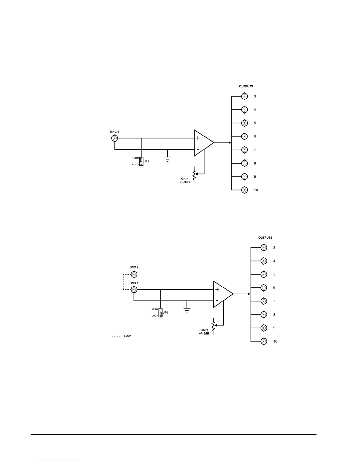
Functional Block Diagrams
This section includes functional block diagrams to illustrate the UDA-8705A functions including the
looping feature.
Figure 1. Simplified Block Diagram of UDA-8705A Functions
Figure 2. Simplified Block Diagram of UDA-8705A with Looping Function

UDA-8705A User Manual (Rev. 1.1) Introduction •1-3
Features
The following features make the UDA-8705A the best solution for general analog distribution:
•8 analog video outputs
•DC Coupled
•Wide adjustable gain range of ±3dB
•Low distortion
•Excellent isolation between outputs
•Power to each card is individually fused
•Fits DFR-8310 and DFR-8320 series frames
•Fully compliant with openGear specifications
•5-year transferable warranty
Documentation Terms
The following terms are used throughout this guide:
•“Frame” refers to the DFR-8300 series frame that houses the UDA-8705A card, as
well as any openGear frames.
•All references to the DFR-8300 series frame includes versions of the 10-slot (DFR-
8310) and 20-slot (DFR-8320) frames and any available options.
•“Operator” and “User” both refer to the person who uses the UDA-8705A.
•“Board” and “Card” both refer to the UDA-8705A unit itself, including all
components and switches.
•“System” and “Video system” both refer to the mix of interconnected production
and terminal equipment in which the UDA-8705A operates.

1-4 •Introduction UDA-8705A User Manual (Rev. 1.1)

UDA-8705A User Manual (Rev. 1.1) Installation and Setup •2-1
Installation and Setup
In This Chapter
This chapter contains the following sections:
•Static Discharge
•Unpacking
•Rear Module Installation (Optional)
•Board Installation
•BNC Labels
•Cable Connections
Static Discharge
Whenever handling the UDA-8705A and other related equipment, please observe all static discharge
precautions as described in the following note:
ESD
Susceptibility
Static discharge can cause serious damage to sensitive
semiconductor devices. Avoid handling circuit boards in high
static environments such as carpeted areas, and when wearing
synthetic fiber clothing. Always exercise proper grounding
precautions when working on circuit boards and related
equipment.
Unpacking
Unpack each UDA-8705A you received from the shipping container, and check the contents against the
packing list to ensure that all items are included. If any items are missing or damaged, contact your
openGear sales representative or Sierra Videodirectly.

2-2 •Installation and Setup UDA-8705A User Manual (Rev. 1.1)
Rear Module Installation (Optional)
The UDA-8705A is compatible with the DFR-8310 and DFR-8320 series frames. The procedure for
installing the Rear Module in your openGear frame is the same regardless of the frame or module used.
However, a different module is required depending on the openGear frame you are using.
Rear Modules for the UDA-8705A
The Rear Module for the UDA-8705A depends on the openGear frame you are installing the card into.
•DFR-8310 series frames — When installing the UDA-8705A in the DFR-8310 series
frames, the R1-8705 or R1L-8705 Rear Modules are required. The UDA-8705A is
also compatible with the DFR-8310-BNC frame.
•DFR-8320 series frames —When installing the UDA-8705A in the DFR-8320 series
frames, the Split Rear Module (R2S-8705) or Full Rear Modules (R2-8705 or R2L-
8705) are required.
Installing the Rear Module
If you received a Rear Module with your UDA-8705A, you will need to install the module in your
DFR-8300 series frame before you can install the UDA-8705A in the frame, or connect cables to the
slot you have chosen for the UDA-8705A. Skip this section if you are installing the UDA-8705A in a
DFR-8310-BNC frame, or the Rear Module is already installed.
Use the following procedure to install the Rear Module in a DFR-8300 series frame:
1. Refer to the DFR-8300 series frame User Manual, to ensure that the frame is properly
installed according to instructions.
2. On the rear of the frame, locate the card frame slot.
3. Remove the Blank Plate from the rear of the slot you have chosen for the UDA-
8705A installation. If there is no Blank Plate installed, proceed to the next step.
4. As shown in Figure 3, seat the bottom of the rear module in the seating slot at the
base of the frame’s back plane.
Figure 3. Rear Module Installation in a DFR-8310 Series Frame (UDA-8705A not shown)

UDA-8705A User Manual (Rev. 1.1) Installation and Setup •2-3
5. Align the top hole of the rear module with the screw hole on the top edge of the
frame back plane.
6. Using a Phillips driver and the supplied screw, fasten the rear module to the back
plane. Do not over tighten.
7. Ensure proper frame cooling and ventilation by having all rear frame slots covered
with Rear Module or blank metal plates. If you need blanks, refer to the chapter,
“Ordering Information” in your DFR-8300 series frame User Manual, and contact
your Sierra Video sales representative.
This completes the procedure for installing the Rear Module in a DFR-8300 series frame.
Board Installation
Use the following procedure to install the UDA-8705A in a DFR-8300 series frame:
1. Refer to the User Manual of your DFR-8300 series frame to ensure that the frame is
properly installed.
2. After selecting the desired frame installation slot, hold the UDA-8705A card by the
edges and carefully align the card edges with the slots in the frame.
3. Fully insert the card into the frame until the rear connection plugs are properly seated
on the midplane and rear modules.
This completes the procedure for installing the UDA-8705A in an DFR-8300 series frame.
BNC Labels
Affix the supplied BNC label, as per the included instructions, to the BNC area on the rear of the rack
frame.
Cable Connections
This section provides instructions for connecting cables to the installed Rear Modules on your DFR-
8300 series frame backplane.
Connections for the DFR-8310 Series Frames
In the DFR-8310 series frames, the UDA-8705A occupies one slot and provides eight analog outputs.
The input of the UDA-8705A can be terminated on the card depending on the rear module used. It is
not necessary to terminate unused outputs.
In the DFR-8310 series frames, the UDA-8705A may be used with the following Rear Modules:
•R1-8705 Full Rear Module — Each card provides eight outputs. The input must be
terminated on the UDA-8705A using JP1. Refer to Figure 4 for cable connections.
•R1L-8705 Full Rear Module — Each card provides eight outputs and one looping
output. If the input is looped on the rear module to another device, JP1 must be set
to LOOP. If looping is not used, either set JP1 to TERM, or terminate the input
externally at BNC 2. Refer to Figure 5 for cable connections.

2-4 •Installation and Setup UDA-8705A User Manual (Rev. 1.1)
Figure 4. Cable Connections for the R1-8705 and
R2-8705 Rear Modules
Figure 5. Cable Connections for the R1L-8705 and
R2L-8705 Rear Modules
Connections for the DFR-8320 Series Frames
In the DFR-8320 series frames, the UDA-8705A may be used with the following Rear Modules:
•R2-8705 Full Rear Module — Each card occupies two slots and provides eight
outputs. The input must be terminated on the card by setting JP1 to TERM. Refer to
Figure 4 for cable connections.
•R2L-8705 Full Rear Module with Looping — Each card occupies two slots and
provides eight outputs plus one looping output. If the input is looped on the rear
module to another device, JP1 must be set to LOOP. If looping is not used, either
set JP1 to TERM, or terminate the input externally at BNC2. Refer to Figure 5.
•R2S-8705 Split Rear Module — Each card occupies one slot and provides four
outputs. Note that each Rear Module provides connections for two cards. Ensure the
input is terminated on the card at JP1. Refer to Figure 6 for cable connections.
Figure 6. Cable Connections for the R2S-8705 Rear Module

UDA-8705A User Manual (Rev. 1.1) User Controls •3-1
User Controls
In This Chapter
This chapter includes the following sections:
•Jumper Locations
•LEDs
•Button Controls
3-2 •User Controls UDA-8705A User Manual (Rev. 1.1)
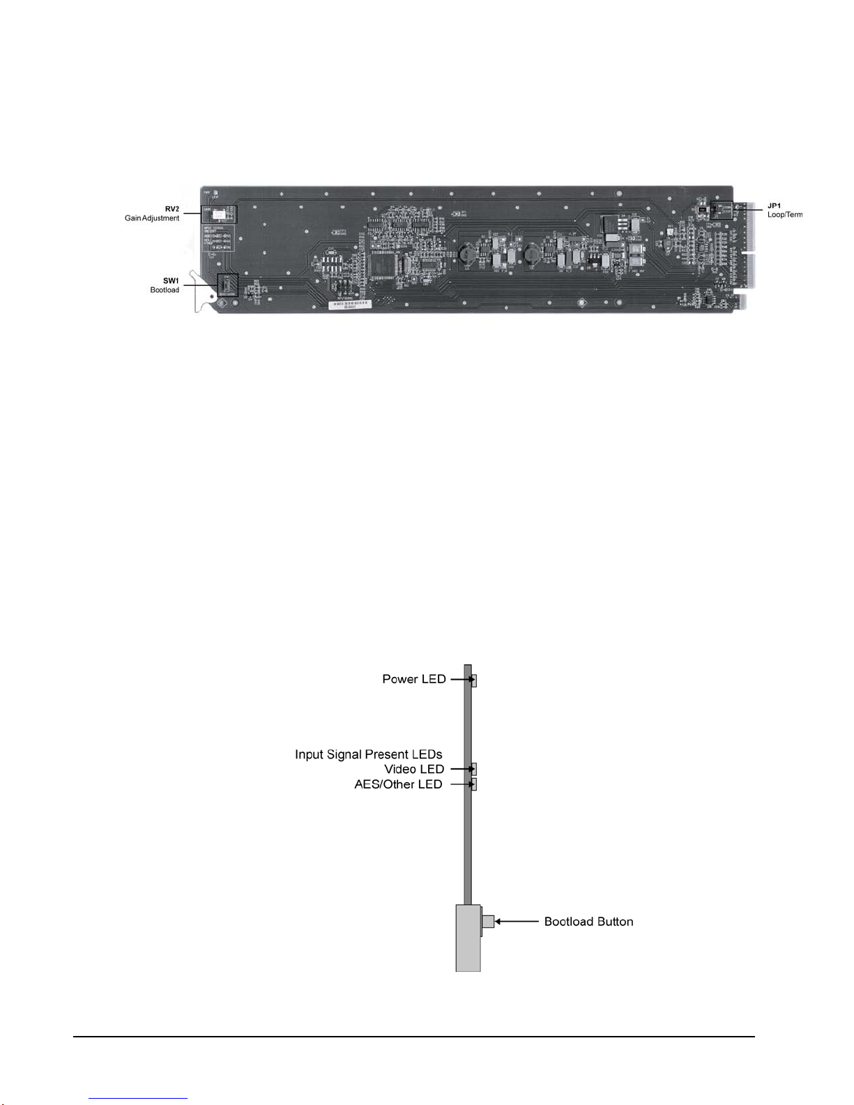
Jumper Locations
The following sections describe the jumpers on the UDA-8705A.
Figure 7. Jumper Locations
JP1 — Local Termination Jumper
The position of JP2 selects an optional 75ohm termination on the input of the UDA-8705A card.
Select one of the following options:
•TERM — Install the jumper in this position to terminate the input signal on this
card. This is the default setting.
•LOOP — Install the jumper in this position to leave the input unterminated. For
example, configure this setting if you wish to loop the signal to another device.
RV2 — Gain Adjustment
The rotation of RV2 adjusts the Gain level of the UDA-8705A and provides a gain range of +/- 3dB.
LEDs
The following sections describe the UDA-8705A LEDs. Refer to Figure 8for LED locations.
Figure 8. LED Locations

UDA-8705A User Manual (Rev. 1.1) User Controls •3-3
PWR (Power) LED
The PWR LED indicates the overall operating status of the UDA-8705A. This LED displays the
following conditions:
•Green — The card is operating normally.
•Flashing Green — The card requires a software upgrade.
•Red — The card is not operational. Refer to the chapter, “Service Information” for
details on this condition.
Input Signal Present LEDs
The Input Signal Present LEDs indicates the status of the analog input. This group of LEDs display
the following conditions:
•VIDEO — If the VIDEO LED is lit, a valid analog video input signal is present on
BNC 1.
•AES/OTHER — If the AES/OTHER LED is lit, a valid AES signal, or some other
analog signal, is present on the input. The signal must be greater than 0.5Vp-p.
Note Slowly changing, or small, amplitude signals will pass through the card, but the
LEDs may be unlit. In this case, it is recommended to disable the Notify on
Input Loss option via DashBoard. Note that the Input Signal Present threshold
is set to assume a level of 1Vp-p.
Button Controls
The following sections describe the UDA-8705A buttons. Refer to Figure 8 for button location.
SW1 — Bootload Button
This button is used for factory service in the unlikely event of a complete card failure. The Bootload
process is further described in the chapter, “Service Information”, of this manual.

3-4 •User Controls UDA-8705A User Manual (Rev. 1.1)
Table of contents
Other Sierra Video Amplifier manuals


