manuals.online logo
Brands
  1. Home
  2. •
  3. Brands
  4. •
  5. Pioneer
  6. •
  7. Amplifier
  8. •
  9. Pioneer DC-111Z User manual

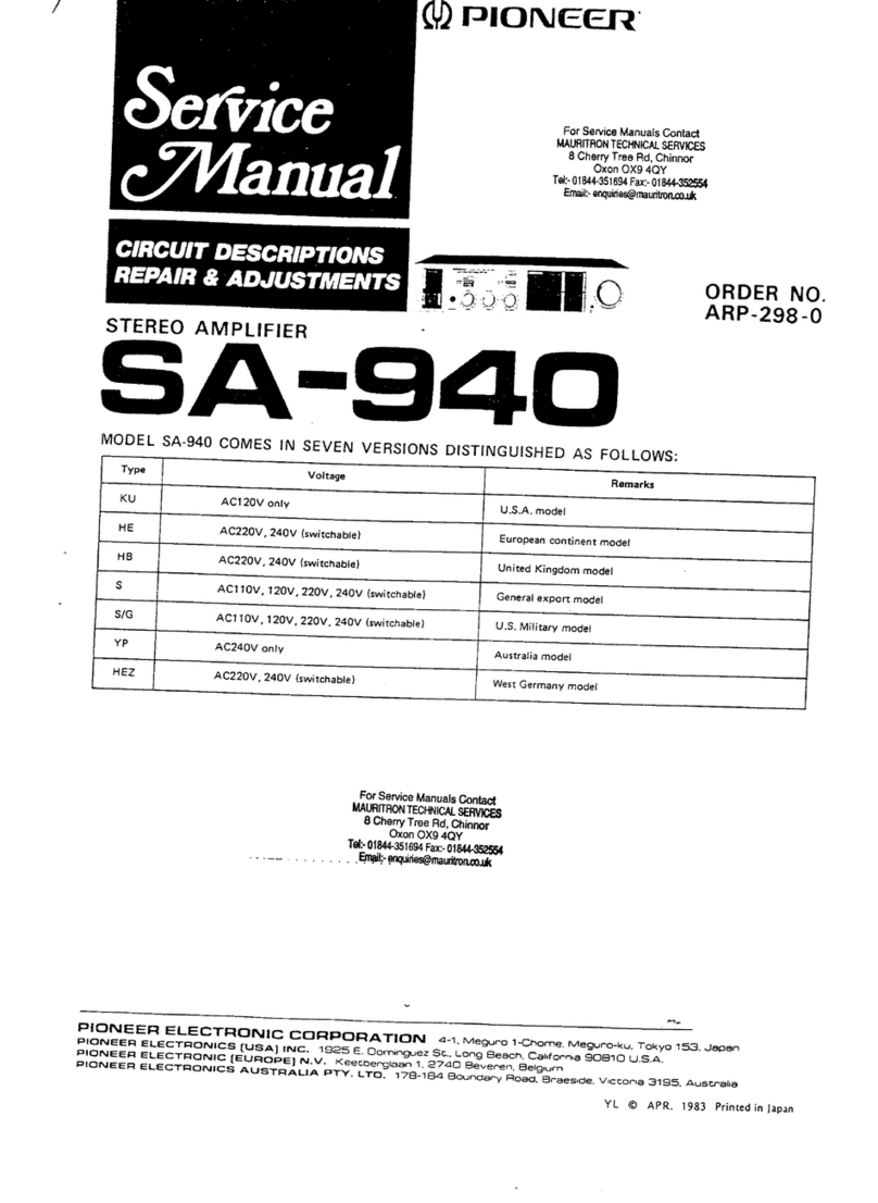
Pioneer DC-111Z User manual

WD)
PIONEER
Setvice
PALEY
ET
CIRCUIT
DESCRIPTIONS
ORDER
NO.
ARP
-
814-0
REPAIR
&
ADJUSTMENTS
STEREO
CASSETTE
TAPE
DECK
AMPLIFIER
C-1117
DC-1102
(Silver
version
of
DC-1112Z)
e
DC-111Z
is
the
same
as
the
DC-110Z
except
for
the
exterior
design
(color).
e
Models
DC-111Z
and
DC-110Z
come
in
seven
versions
distinguishes
as
follows:
Applicable
model
DC-111Z
DC-110Z
i
Oo
AC
120V
only
U.S.A
Power
requirement
Destination
AC
220V
(240V)*
(Switchable)
European
continent
a
idl
AC
240V
(220V)*
(Switchable)
United
Kingdom
AC
110V/120V/240V
(Switchable)
General
market
4
AC
240V
only
Australia
AC
120V
only
Canada
AC
220V
(240V)*
(Switchable)
West
Gemany
*
Change
the
primary
wiring
of
the
power
transformer.
This
service
manual
is
applicable
to
the
KU,
HE,
HB,
S
and
YP
types.
As
to
the
HE,
HB,
S
and
YP
types
please
refer
to
the
page
46.
As
to
the
KC
type,
please
refer
to
the
additional
service
manual
(ARP-813).
As
to
the
HEZ
type,
please
refer
to
the
additional
service
manual
(ARP-815).
Ce
manual
d’instruction
se refer
au
mode
de
réglage,
en
francais.
(P36-P40)
Este
manual
de
servicio
trata
del
método
adjuste
escrito
espanol.
(P41-P45)
PIONEER
ELECTRONIC
CORPORATION
4-1,
Meguro
1-Chome,
Meguro-ku,
Tokyo
153,
Japan
PIONEER
ELECTRONICS
[USA]
INC.
P.O.
Box
1760,
Long
Beach,
California
90801
U.S.A.
TEL:
(800)
421-1404,
(B00)
237-0424
PIONEER
ELECTRONIC
[EUROPE]
N.V.
Keetberglaan
1,2740
Beveren,
Belgium
TEL:
03/775:28:08
PIONEER
ELECTRONICS
AUSTRALIA
PTY.
LTD.
178-184
Boundary
Road,
Braeside,
Victoria
3195,
Australia
TEL:
(03)
580-9911
SA:
APR.
1985
Printed
in
Japan
DC-1112/1102
CONTENTS
1.
SPECIFICATIONS
..........
00.00.00
cues
2
2.
FRONT
PANEL
FACILITIES
................
3
3.
DISASSEMBLY
.........
0.0.0...
0c
ee
eee
4
4.
PARTS
LOCATION
.............0000
eee
uue
9
Bi
“PACKING
osca
esac
pectiaees
tie
Wain
accra
acne
11
6.
EXPLODED
VIEW
............
000
eee
eee
12
7.
ELECTRICAL
PARTS
LIST
.................
18
8.
P.C.
BOARDS
CONNECTION
DIAGRAM
.....
21
1.
SPECIFICATIONS
AMPLIFIER
SECTION
Continuous
Average
Power
Output
is
25
Watts*
per
channel,
min.,
at
8
ohms
from
40
Hertz
to
20,000
Hertz,
with
no
more
than
0.3%
total
harmonic
distortion.
*Measured
pursuant
to
the
Federal
Trade
Commission's
Trade
Regulation
rules
on
Power
Output
Claims
for
Amplifiers.
Continuous
Power
Output
40
to
20,000HZ
oo.
eceeeseseeeeceeeeeees
25W
+
25W(T.H.D.
0.3%
8
ohms}
TkHz(DIN)
oo...
--.
32
W
+
32
W(T.H.D.
1%
8
ohms}
1
kHz
(DIN
music
power)
...
..
45W
+
45
W(T.H.D.
1%
8
ohms}
Hum
and
Noise
(IHF,
short-circuited,
A
network)
PHONG?
eovescocteas
crattang
ian
Fader
scan
seaseavivl
Realeceoea
delet
72
dB
Hum
and
Noise
(DIN
continuous
Power/50
mV)
PHONO’
essential
Av
aces
adeat
dcbtecehees
sera
ed
ode
dolce
ob
68
dB/60
dB
Total
Harmonic
Distortion
(40
Hz
to
20,000
Hz,
8
ohms),
from
CD/VIDEO
12.5
Watts
per
channel
power
output
..........0000ececcces
No
more
than
0.2%
9.
SCHEMATIC
DIAGRAM..................0.
25
10.
BLOCK
DIAGRAM
................0000a
ee
29
11.
CIRCUIT
DESCRIPTIONS
.................
30
12.
ADJUSTMENTS
...........
0...
cece
ee
ees
31
REGIAGE
ik
GaAs
costar
cde
wey
eects
cima
ed
36
BIUSTE”
shsctig
abe
bat
eit
ile
a
teatereeehd
Bete
s
41
13.
FOR
HE,
HB,
S
AND
YP
TYPES...........
46
14.
SAFETY
INFORMATION
..................
48
Tape
Deck
Section
PSV
BRGITIS
wedi
sic
rexvhas
srceatn
bos
Cha
acces
cove
andleedca
Shee
4
track,
2-channel
stereo
Heads:
ict
ctcses
tetincesodeseeeaeh
et
“Hard
Permalloy’’
recording/
playback
head
x
1
“Ferrite”
erasing
head
x
1
Rajon
ee
scar
aapnesieeuuic
tacstonnes
se
rauceuepavuauasates
feteetmteenees
DC
servo
motor
x
1
No
more
than
0.08%
(WRMS)
No
more
than
+0.20%
(DIN)
Fast
Winding
Time
................000cc00eeee
Approximately
115
seconds
(C-60
tape)
Frequency
Response
—20
dB
recording:
Norimal
tapes.
vid
ca
sansscetge
cisbuncsisgesate
eho
sohedaseatace
aadork
35
to
13,000
Hz
Metal
tapes:
ni
.sis
caccteiesdcacaveasi
ona
sader
ase
cu
eset
erevel
chougeeuee
35
to
15,000Hz
Signal-to-Noise
Ratio
Dolby:
NR
OFB:
aces
csesaessaeegeseceteusane
cdedddeccuse
sin
shacetasiees
More
than
55
dB
Noise
Reduction
Effect
Dolby
NR
Btype
ON
uu...
eee
More
than
10
dB
(at
5
kHz)
Furnished
Parts
Operating
Instructions
.........0::cccccccccceccessccussecetsssseccesnsnusansesaceveesersinens
1
Miscellaneous
Power
requirements
KU
and
KC
models
.........
cece
cceseseccctsvescceeseessarausaeascees
AC
120
V,
60
Hz
HE
model
.............
AC
220
V,
50/60Hz
HB
and
YP
models
AC
240
V,
50/60
Hz
S
and
S/G
models
..........
AC
110
V/120
V/220
V/240
V,
50/60
Hz
(switchable)
Power
Consumption
KUO)
rset
estas
eek
cal
pete
eens
be
nae
oi
199
W
KO
MOdel:
0.
oo:
ester
dnereadards
deck
idbaedd
cds
iantaacaidqevea
eg
tietaceeacde
ees
199
W
HE,
HB,
and
YP
models
.
.
270
W
SANG:
S/GiMOdels
35.6035)
eevee
ates
A
ettacs
Ses
WEED
douse
dais
tect
hieste
199
W
DMCS:
6
cocse
act
daon
vv
ciserceven
nn
Shasaveesawcdes
420(W)
x
188(H)
x
224
(D)
mm
16-9/16(W)
x
7-6/16(H)
x
8-13/16(D)
in
Weight
(without
package)
...............cccccceeeeseeseeeecececseeraus
5.5
kg
(12
Ib
2
oz)
QUESTIONNAIRE
MODEL
One
Model
per
questionnaire
Dear
Servicer,
Thank
you
for
your
cooperation
in
the
post-sale
service
of
Pioneer
products.
This
questionnaire
is
used
as
a
tool
to
improve
the
serviceability
of
our
products
and
service
manuals.
Please
evaluate
this
model
and
service
manual
by
answering
the
following
questions.
Your
ideas
may
be
realized
in
our
future
products.
Your
answers
will
be
appreciated.
Thank
you.
PIONEER
ELECTRONIC
CORP.
T.
Nakagawa,
Manager,
Service
Section,
International
Division
1.
SERVICING
EVALUATION
Circle
applicable
number:
Good
Fair
Poor
Disassembly
/Re-assembly:
b.
Circuit
Checks:
1
gS
8
4
8G
c.
Replacement
of
Parts:
1
2 3
*4
*5
d.
Adjustment
(s):
1
2.
8
¥4
5
*
If
(4)
or
(5)
was
circled,
please
be
specific.
e.
Your
advice,
opinion
or
ideas
related
to
servicing
this
product.
SERVICE
MANUAL
EVALUATION
Circuit
&
Mechanism
Description
Circuit
Diagram
OTHER
Please
describe
other
areas
of
servicing
which
you
may
find
difficult.
Completed
by
:
Company
Name
:
Address
:
City/State/Zip
:
Please
send
this
form
filled
to
the
distributor
in
your
country.
2.
FRONT
PANEL
FACILITIES
@
POWER
indicator
@
POWER
switch
@
HEADPHONES
jack
@
GRAPHIC
EQUALIZER
controls
By
operating
these
five
controls,
equalization
effects
can
be
added
to
program
source
or
tape
playback
sounds.
@
BALANCE
control
@
FUNCTION
switches
TAPE
(
00
):
Push
when
playing
back
tapes.
CD/VIDEO
(
0°
):
Push
when
listening
to
a
component
connected
to
the
CD/VIDEO
terminals.
DC-1112/110Z
TUNER
(
*
}:
Push
when
listening
to
broadcasts
on
the
tuner.
PHONO
(
@
):
Push
when
playing
records
on
the
turntable.
VOLUME
control
REC
switch
(
©
)
PLAY
switch
(
>
}
REW
switch
(
<
)
FF
switch
(
>
)
e@ee86
0 8
PAUSE
switch
(
0
)
@
STOP/
EJECT
switch
(
~
)
@
TAPE
COUNTER
@
RESET
button
Push
this
button
to
reset
the
tape
counter
display
to
000.
@
REC
indicator
This
lights
during
the
recording
mode.
@
*DOLBY
NR
switch
Push
this
switch
to
ON
when
recording
with
the
built-in
Dolby
noise
reduction
system
(B
type),
and
when
playing
back
tapes
which
have
been
recorded
using
the
system.
aia
h
1
hhh
tha
TA
AAAS
AUT
A
TATA
TATA
*Noise
Reduction
manufactured
under
ticense
from
Dolby
Laboratories
Licens-
ing
Corporation.
“Dolby”
and
the
double-D
symbol
are
trademarks
of
the
Dolby
Laboratories
Licensing
Corporation.
Iai
1h ih
11h
1A
ThA
AA
TAA
AAA
AAA
ATA
ATA
AACA
TOT
DC-1112/110Z
3.
DISASSEMBLY
Cassette
Replacement
Procedures
1.
2.
3.
4
Remove
7
pieces
of
screw
dd).
Remove
Bonnet
case.
Remove
2
pieces
of
screw
Q)
and
|
piece
of
nut
Q).
Push
the
claw
at
the
bottom
of
chassis,
remove
the
Front
panel
assembly,
and
pull
out
toward
you.
Remove
the
LED
assembly
(A)
and
(B)
from
the
Front
panel
assembly.
Remove
6
pieces
of
screw
GB).
and
enable
the
Power
amplifier
assembly
to
move
upward.
(See
Fig.
3-2)
Front
panel
——____
assembly
Knob
{VOLUME}
ge
10.
Fig.
3-1
Remove
connectors
J7,
J11
and
J21
of
the
wiring
coming
out
of
the
Tape
transport
unit.
(Separate
the
Front
panel
assembly
from
the
main
body.)
Open
the
Cassette
door.
(See
Fig.
3-3)
Remove
4
pieces
of
screw
(4).
Remove
Counter
belt
from
Tape
counter,
and
hook
onto
the
Tape
transport
unit.
Remove
the
Tape
transport
unit
from
the
Front
panel
assembly.
LED
assembly
(A)
DC-1112/110Z
Power
amplifier
assembly
Connector
J21
SS
ea
Connector
J11
eae
Connector
J7
/
Tape
transport
unit
Fig.
3-2
Cassette
door
Front
panel
assem
bly
Tape
transport
unit
Counter
belt
Fig.
3-3
DC-1112/110Z
COMPONENT
PARTS
REPLACEMENT
PROCEDURES
Replacement
of
Motor
1.
Remove
lead
wire
of
motor
terminal.
8.
While
applying
a
Belt
to
the
flywheel
side,
attach
2.
Remove
set
screw
(1)
and
detach
Motor
holder.
Motor
plate
to
Tape
transport
unit.
3.
Remove
2
set
screws
(2),
and
detach
the
Motor.
9.
Apply
Belt
to
driving
pulley
and
pulley.
4.
Pull
out
Motor
pulley
from
Motor.
10.
Solder
lead
wire
to
motor
terminal.
5.
Attach
Motor
pulley
to
new
motor.
11.
Fasten
securely
head
lead
and
control
lead
with
6.
Adjust
the
height
of
Motor
pulley.
(see
Fig.
3-4-1)
binder.
7.
Attach
Motor
to
Motor
holder.
12.
Adjust
the
tape
speed.
Leadwire
Tape
transport
unit
Motor
holder
Motor
pulley
Motor
Fig.
3-4
DC-1112/110Z
4.
Apply
belt
to
driving
pulley
and
pulley.
Fasten
securely
head
lead
and
control
lead
with
binder.
6.
Adjust
the
tape
speed.
Replacement
of
Belt
1.
Remove
set
screw
(1)
and
detach
Motor
holder
the
Tape
transport
unit.
2.
Replace
the
old
belt
with
a
new
one.
3.
While
applying
the
Belt
on
the
flywheel
side,
attach
Motor
holder
to
the
Tape
transport
unit.
my
Motor
holder
Tape
transport
unit
Fig.
3-5
DC-1112/1102Z
Replacement
of
Head
1.
Detach
cassette
knob.
7.
Check
the
running
of
tape.
2.
Remove
head
lead
from
head.
8.
Perform
azimuth
adjustment.
3.
Remove
set
screw
qd)
of
head.
9.
Perform
bias
adjustment.
4.
Remove
former
head
and
install
a
new
one.
5.
Solder
the
head
lead
while
taking
precaution
not
to
touch
the
wirings.
6.
Attach
cassette
knob.
Head
lead
wires
Cassette
knob
REC/PB
head
Erase
head
Erase
head
\
Agta
te
REC/PB
head
Fig.
3-6
4.
PARTS
LOCATION
NOTES:
e
The
A,
mark
found
on
some
component
parts
indicates
the
importance
of
the
safety
factor
of
the
part.
Therefore,
when
replacing,
be
sure
to
use
parts
of
identical
designation.
e
For
your
Parts
Stock
Control,
the
fast
moving
items
are
indicated
with
the
marks
* *
and
*.
*&%*
GENERALLY
MOVES
FASTER
THAN
*
This
classification
shall
be
adjusted
by
each
distributor
because
it
depends
on
model
number,
temperature,
humidity,
etc.
Front
Panel
View
(DC-111Z)
Knob
(STOP/EJECT)
AAY-106
Knob
(PAUSE)
Tape
counter
AAW-140
%
LED
(REC)
AAY-105
AEL-388
Knob
(FF)
Bonnet
case
AAY-104
ANE-543
Knob
(REW)
AAY-103
Knob
(PLAY)
AAY-102
Knob
(REC)
Knob
(DOLBY
NR)
AAY-101
AAY-099
*LED
(POWER)
AEL-388
Knob
(VOLUME)
AAB-412
Knob
(POWER)
AAY-200
Phone
Jack
(PHONES)
AKN-049
Knob
(FUNCTION)
AAY-098
*
Variable
resistor
assembly
Knob
(BALANCE)
ACX-311
AAB-411
DC-1112/1102
Rear
Panel
View
(DC-111Z)
Terminal
(TUNER)
Terminal
(SPEAKERS)
AKP-083
AKE-109
A\AC
power
cord
Terminal
(DC
SUPPLY)
ADG-073
AKN-034
Terminal
(PHONO,
CD/VIDEO)
AKB-094
*
Variable
resistor
(INPUT)
ACT-198
Top
View
(DC-1112Z)
#x*
Fuse
(2.5A,FU4,5)
AEK-123
**
Fuse
(1.6A,FU3)
AEK-121
Fuse
holder
assembly
A\
*&*
Fuse
(2A,FU1)
AEK-122
Power
amplifier
assembly
GWH-179
A\
x
Power
transformer
(120V)
ATS-196
Complex
assembly
GWM-388
Switch
assembly
*
x
Push
switch
(FUNCTION)
*
Variable
resistor
SUJ6L4B2B2B2LF
(VOLUME)
ACT-197
10
DC-1112/1102
5.
PACKING
6.
EXPLODED
VIEW
NOTES:
Mark
No.
Part
No.
Description
e
Parts
without
part
number
cannot
be
supplied.
1
AHA-400
Front
pad
e
The
A\
mark
found
on
some
component
parts
indicates
the
importance
of
the
2
AHA-401
Rear
pad
safety
factor
of
the
part.
Therefore,
when
replacing,
be
sure
to
use
parts
of
identical
Bi
ke
designation.
4
AHE-527
Packing
case
for
DC-1112Z
e
For
your
Parts
Stock
Control,
the
fast
moving
items
are
indicated
with
the
AHE-528
Packing
case
for
DC-110Z
inaene
SS
one
*&*&
GENERALLY
MOVES
FASTER
THAN
*
This
classification
shall
be
adjusted
by
each
distributor
because
it
depends
on
model
5
ARB-679
Operating
instructions
number,
temperature,
humidity,
etc.
(English)
Parts
List
of
Exterior
(DC-111Z)
Regarding
DC-1102Z,
see
the
table
in
page
11.
Mark
No.
Part
No.
Description
Mark
No.
Part
No.
Description
1
GWH-179
Power
amplifier
assembly
xx
=
35
AEB-197
Counter
belt
2
GWM-388
Complex
assembly
36
AEC-847
Leg
assembly
*
3
ACX-311
Variable
resistor
assembly
A
37.
ADG-073
AC
power
cord
1
A
4
ATS-196
Power
transformer
(120V)
38
BBZ30PO80FZK
Screw
3x8
39
NKSOFUC
Nut
A
kk
5
ASG-539
Push
switch
(POWER)
A
kk
6
AEK-122
FU1
Fuse
(2A)
40
ABA-286
Séieyy
Ake
7
AEK-121
FU3
Fuse
(1.6A)
41
VMZ30PO60FMC
Screw
3x6
A
kk
8
AEK-123
FU4,5
Fuse
(2.5A)
42
BPZ30PO80FZK
Screw
3x8
9
AAW-140
Tape
counter
43.
PBZ20PO40FMC
Screw
2x4
44
VPZ30
PO80FMC
Screw
3x8
10
ANZ-044
Damper
assembly
11
AAB-411
Knob
(BALANCE)
100
Fuse
holder
Assembly
12
AAB-412
Knob
(VOLUME)
101
Switch
assembly
oi
Ree
Knob
(POWER)
102
Headphone
jack
assembly
1
AAY-098
Knob
(FUNCTION)
103
LED
assembly
(A)
104
LED
assembly
(B)
15
AAY-099
Knob
(DOLBY
NR)
16
AAY-101
Knob
(REC)
17
AAY-102
Knob
(PLAY)
105
Tape
transport
unit
18
AAY-103
Knob
(REW)
106
Chassis
19
AAY-104
Knob
(FF)
107
Bottom
plate
108
Rear
panel
Contrast
of
Miscellaneous
parts.
20.
AAY-105
Knob
(PAUSE)
109
Heat
sink
holder
21
AAY-106
Knob
(STOP/EJECT)
Key
No.
Symbol
&
Description
DO111z
|
pe-rt0z
|
Remarks
23.
ANM-888
Front
panel
111
Damper
holder
24
ANR-964
Door
(L)
112
REC
lever
16
|
Knob
A
(REC)
AAY-101
AAY-085
113
REC
base
17
|
Knob
B
(PLAY)
AAY-102
AAY-086
ei
eae
PTA
Mae
2
18
Knob
C
(REW)
AAY-103 AAY-087
19
|
Knob
D
(FF)
AAY-104 AAY-088
27
ANZ-032
POWER
panel
115
Switch
barrier
20
|
Knob
E
(PAUSE)
AAY-105
AAY-089
5
ANZ-037
Deck
panel
116
Clamp
plate
21
‘|
Knob
F
(STOP/EJECT)
AAY-106
AAY-090
ANZ:086
Amp
panel
23
Front
panel
assembly
ANM-888
ANM-949
26
Name
panel
ANZ-039
ANZ-043
30
AAX-426
Shine
paper
Deck
panel
ANZ-037
ANZ-042
31
ABH-156
REC
spring
Amp
panel
ANZ-055
ANZ-056
32
ABH-147
Coiled
spring
33
ABH-149
Rod
34
ABK-012
Keep
plate
11
12
DC-1112/1102Z
Exterior
N
fe)
o
bo
™~s
N
c
c
=
1
O
OQ
Tape
Transport
Unit
\
;
1
|
Parts
List
of
Tape
Transport
Unit
Mark
x*
kk
kk
xn
xk
xk
Part
No.
AXV-087
AXT-007
AXW-034
AXV-064
AXS-078
AXV-088
AXS-079
AXP-037
AXV-089
AXS-080
AXP-038
AXP-039
AXS-081
AXV-090
AXS-082
AXS-083
AXV-091
AXS-099
AXV-092
AXV-093
AXS-084
AXS-085
AXS-086
AXV-094
AXS-087
AXS-088
AXP-040
AXV-095
AXS-089
AXS-091
AXS-092
AXS-093
AXV-096
AXW-035
AXW-036
AXP-041
AXS-101
AXP-042
AXV-104
AXS-094
AXS-095
AXV-098
AXS-096
NOTES:
e
Parts
without
part
number
cannot
be
supplied.
e
The
/\
mark
found
on
some
component
parts
indicates
the
importance
of
the
safety
factor
of
the
part.
Therefore,
when
replacing,
be
sure
to
use
parts
of
identical
designation,
e
For
your
Parts
marks
* *
and
*
.
*&*
GENERALLY
MOVES
FASTER
THAN
*
This
classification
shall
be
adjusted
by
each
distributor
because
it
depends
on
model
number,
temperature,
humidity,
etc.
Description
Torsion
spring
Bush
Felt
Compression
spring
Head
base
Torsion
spring
FR
arm
P
idler
assembly
Torsion
spring
Reset
lever
T
reel
assembly
S
reel
assembly
FR
release
lever
Torsion
spring
P
release
lever
PL
plate
Torsion
spring
FR
plate
S
brake
spring
Torsion
spring
F
idler
gear
Sensor
cam
AS
gear
Cassette
holder
Eject
cam
Latch
lever
Pinch
arm
assembly
Torsion
spring
SE
lever
FF
lever
REW
lever
PL
lever
B
Torsion
spring
Thrust
receptacle
Belt
Flywheel
assembly
Motor
pulley
FR
idler
arm
assembly
Torsion
spring
Assist
gear
A
Assist
gear
B
Torsion
spring
P
cam
lever
CR
cam
lever
Stock
Control,
the
fast
moving
items
are
indicated
with
the
Mark
No.
Part
No.
Description
46
Axv-099
Torsion
spring
47
AXS-106
FR
start
lever
48
AXV-100
Torsion
spring
49
AXv-101
Torsion
spring
50
AXV-102
Torsion
spring
51
AXS-098
Interlock
plate
52
AXS-090
Pause
lever
53
AXS-100
REC
lever
54
AXV-103
Lock
pin
55
BD2Z26PO50FMC
Screw
2.6x5
56
BTZ20PO80FMC
Screw
2x8
57
BMZ20P100FMC
Screw
2x10
58
PTZ26PO60FMC
Screw
2.6xX6
BOS
“eA
AR
aa
2
OS
Ase.
60
BTZ26PO60FMC
Screw
2.6x6
61
PMA26PO40FMC
Screw
2.64
62
PDZ26PO40FMC
Screw
2.6x4
63
NA20FMC
Nut
M2
64
WA16D040D020
Washer
1.6x4x0.2
65
WA21D040D030
Washer
2.1x4x0.3
xx
66
AXN-031
REC/PB
head
x
67
AXN-032
Erase
head
xx
68
AXN-023
Motor
xx
69
AXN-024
Spring
switch
(S12,
METAL)
xk*e
=
70
AXN-025
Spring
switch
(S11,
MUTE)
71
AXS-102
REC
link
lever
72°
AXV-106
Tension
spring
101
Button
shaft
102
Grounding
lug
103
Chassis
104
105
Gear
holder
106
Motor
holder
107
FR
S
lever
108
Protector
109
PL
start
lever
110
RS
W
lever
111
REC
protector
112
REC
change
plate
113
Lug
114
Cord
fixer
115
Wire
tie
116
Lug
terminal
17
7.
ELECTRICAL
PARTS
LIST
NOTES:
When
ordering
resistors,
first
convert
resistance
values
into
code
form
as
shown
in
the
following
examples.
Ex,
1
When
there
are
2
effective
digits
(any
digit
apart
from
0),
such
as
560
ohm
and
47k
ohm
(tolerance
is
shown
by
J=5%,
and
K=10%
).
5602
56
x
10!
S61
iinaris
RD%‘%PS
BOM
J
47kQ
47
x
10°
473....,
RD%‘%PS
AMG
J
0.52
ORS?
oi
ores
BGS
BAS
hel
oa
oe
RN2H
K
12
O10
sn eG
ene
ee
ae
eee
RSiIP
GWM
K
Ex.
2
When
there
are
3
effective
digits
(such
as
in
high
precision
metal
film
resistors).
5.62k2
562
x
10!
5621
....
RN%SR
BOQW
F
e
The
4,
mark
found
on
some
component
parts
indicates
the
importance
of
the
safety
factor
of
the
part.
Therefore,
when
replacing,
be
sure
to
use
parts
of
identical
designation.
e
For
your
Parts
Stock
Control,
the
fast
moving
items
are
indicated
with
the
marks
**
and
*
.
*%*
GENERALLY
MOVES
FASTER
THAN
*
This
classification
shall
be
adjusted
by
each
distributor
because
it
depends
on
model
number,
temperature,
humidity,
etc.
Miscellaneous
Parts
P.C.
BOARD
ASSEMBLIES
Complex
Assembly
(GWM-388)
SEMICONDUCTORS
Mark
Symbol
&
Description
Part
No.
Mark
Symbol
&
Description
Part
No.
Power
amplifier
assembly
GWH-179
xx
10701,
1C702
BA3812L
Complex
assembly
GWM-388
xx
10401
HA12045
Switch
Assembly
Non
supply
xx
10501
M5218L
Headphone
jack
assembly
Non
supply
xx
=1C601
M5218P
Fuse
holder
assembly
Non
supply
xx
1C301
M5220L
LED
assembly
(B)
Non
supply
LED
assembly
(A)
Non
supply
x*
§='Q842
DTA143ES
(RN2201)
SWITCH
**
0810,
0841
DTC124ES
ee
(RN1203)
Mark
Symbol
&
Description
Part
No.
eke
Q801
2SA933S
4.
x
S1
Push
switch
(POWER)
ASG-539
(2SA1048)
Q408,
0409,
0501, Q502,
(2SC2458)
Mark
Symbol
&
Description
Part
No.
Q505,
Q506,
0846
A
ok
T1
Power
transformer
ATS-196
we
=
0843
2SC2603
(AC120V)
(2SC2458)
xx
0844,
0845
2$D438
RESISTOR
*x*
=§=Q301,
0302
2SC2878
Mark
Symbol
&
Description
Part
No.
x
D833
RD5.6EB
: :
:
(HZ5.6EB)
*
VR1
Variable
resistor
assembly
ACX-311
*
D401,
D402,
D808,
D822,
188131
(GRAPHIC
EQUALIZER)
D840—D843
FUSES
SWITCHES
Mark
Symbol
&
Description
Part
No.
Mark
Symbol
&
Description
Part
No.
&
x
FU4,
FUS
Fuse
(2.5A)
AEK-123
,
d
4.
&*
FUL
Fuse
(2A)
AEK-122
x*
=
§=S401
Slide
switch
ASH-105
A,
*&*
FU3
Fuse
(1.6A)
AEK-121
(REC/PB)
*x*
$701
Push
switch
SUJ6L4B2B2B2LF
(FUNCTION)
OTHERS
Mark
Symbol
&
Description
Part
No.
A
AC
Power
cord
ADG-073
A
C1
Ceramic
capacitor
ACG-502
18
Mark
Ss
COILS
AND
Mark___
Sy
T8
CAPACITOR
c8
COILS
AND
TRANSFORMERS
Mark
Symbol!
&
Description
Part
No.
Headphone
Jack
Assembly
Mark
Symbol!
&
Description
Part
No.
C717,
C718
CKCYX153M25
eters
Mark
Symbol
and
Description
Part
No.
F401,
F402
MPX
filter
ATF-158
(CKDYX153M25)
C105,
C106
CCCSL470J50
L801
Inductor
ATH-094
C707,
C208
CKCYX183M25
Mark
Symbol
&
Description
Part
No.
(CCDSL470J50)
L501,
L502
Inductor
ATH-117
(CKDYX183M25)
1401,
1402
Trap
coil
ATM-031
C703,
C704
CKCYX393M25
R829,
R830
RD1/2PM331
J
C101,
C102
CCCSL101J50
L503,
L504
Trap
coil
ATM-032
(CKDYX393M25)
(CCDSL101J50)
OTHERS
C119
CEASR47M100
T801
Oscillator
transformer
ATX-036
C713,
C714
ae
Mark
Symbol.
&
Descripucn
park
No.
C113,
C115,
C116
CEAS100M50
( }
C107,
C108
CEAS101M10
CAPACITORS
C806,
C808
CQMA153J50
Phone
jack
(PHONES)
AKN-049
C503,
C504
CQMA182J50
eee
Syania
a
ensane
ae
C109,
C110,
C118
CEAS101M25
ar
rele
escupien
an
No.
C421,
C422
CQMA183J50
LED
Assembly
(A)
C114
CEAS101M50
C804
Polypropylene
ACE-133
SEMICONDUCTOR
C103,
C104
CEAS2R2M50
(1500p/630V)
a
oe
O07
2908;
PONibe2
350
C126,
C127
CEAS330M25
C723,
C724
Ceramic
ACG-028
pales
,
cain
bawanasee
Mark
Symbol
&
Description
Part
No.
C130
CEAS332M25
(330p/50V)
D828
LED
(REC
AEL-388
C417,
C418
Electrolytic
ACH-387
pednocadec
COMASS
2200
i
(BEE)
C111,
C112,
C124,
C125
CEAS470M25
|
C511,
C512
COMA393J50
|
(0.27/50V)
C133
CEAS470M50
bra
Bara
LED
Assembly
(B)
C117
CEAS471M6
C419,
C420
Electrolytic
ACH-388
COMA
Fi
edn)
SEMICONDUCTOR
C120,
C121
CKCYF473250
C309,
C310
COMA562J50
lexpyra7azeGl
(0.82/50V)
C613,
C614
CQMA822J50
Mark
Symbol
&
Description
Part
No.
C305,
C306,
C605—C608
CCCSL101J50
D827
LED
(POWER)
AEL-388
RESISTORS
38)
(CCDSL101
J50)
*
C802,
C803
CCCSL101
K500
RESISTORS
.
Power
Amplifier
Assembly
(GWH-179)
re
: ,
NOTE:
When
ordering
resistors,
convert
the
resistance
value
(CCDSL101K500)
NOTE:
When
ordering
resistors,
convert
the
resistance
value
8
into
code
form,
and
then
rewrite
the
part
no.
as
before.
Part
No.
into
code
form,
and
then
rewrite
the
part
no.
as
before.
SEMICONDUCTORS
BA3812L
C403,
C404,
C429,
C430
CCCSL470J50
mask
eae
‘i
ey
Mark
Symbol
&
Description
Part
No.
Mark
Symbol
&
D
ipti
Part
No.
ar’
ymbol
&
Description
art
No.
,
HA12045
Ree
hia
ese
eli
Yoo
So
Secupton
£
A
R129,
R130
RD1/2PMFOO
OJ
M5218L
as,
CEASAATRIEO
*
VR701
Variable
(BALANCE)
—
ACT-057
A
ee
1101
STK4141-2S
R133,
R137,
R138
RD1/2PMOOQS
M5218P
peeioe
CEASHEBRICG
*
VR7O2
Variable
(VOLUME)
ACT-197
we
10102,
1C103
MPC78M12H
A
R125,
R126,
R141,
R142,
RD1/4PMFOOQSJ
M5220L
'
*
VR6O1
Variable
(INPUT)
ACT-198
xe
=
0104
2SB834
R134,
R118, R119,
R120,
R136
i-fi
**
§=§Q101—0103
2SC1740S
DTA143ES
C303,
C304, C423, C424.
CEASO10M50
*
VR841,
VR842
pea
fixed
VRTB6VS224
(28€2603)
R124
RS1LMF681J
eae
he
ae
aie
i
eas
sh
*
VR301,
VR302, VR5O1,
VRTB6VS223
R131
RS2LMF221J
RN1203
C425,
C426,
C501,
C502.
pecan
V
Bb
O2
caenienneae
2k
ee
Spastape
oe
Reeves
Dohoese
C519, C520, C701,
aoe
Bese
BDI
ier
Me
oie
ae
A
peti
an
Aldea
2SA1048
C727,
C728,
C814
;
R319,
R320
RD1/4PM105J
*
D105
RD13EB
Other
resistors
RD1/4PMOOQJ
)
:
aia
Other
resistors
RD1/8PMO
Og
(HZ13EB)
A
*
D103,
D104,
D107—D110
$5566
OTHERS
28C1740S
C453,
C725,
C726
CEAS101M16
OTHERS
(112)
we
(2SC2458)
C401,
C402,
C405,
C406,
CEAS2R2M50
a5
3
Mark
Symbol
&
Description
Part
No.
Rees
C427,
C428,
C452,
C603,
C604 Mark
Symbel:6.
Description
paren:
*
D102
1$2471
Terminal
(SPEAKERS)
AKE-109
cee
Se
lpenee
CEAS221M16
Terminal
(PHONO,
CD/VIDEO)
AKB-094
Terminal
(DC
SUPPLY)
AKN-034
)
RELAY
Terminal
(TO
TUNER)
AKP-083
C307,
C308,
C505,
C506
CEAS330M16
F
S
ABA-271
250438
C415,
C416
CEAS4R7M50
Switch
Assembly
Mark
Symbol
&
Descripti
ane
AEC-940
ar
mbo
escription
Part
No.
eat
proof
rivet
-
eee
C609,
C610
CEAS470M10
SWITCHES
Y P
ane
:
:
C351, C352,
C651,
C652,
CEAS470M1
oat
*
*
RY101
Rela
ASR-
(HZ5.6EB)
C751,
C809.
C810
§
Mark
Symbol
&
Description
Part
No.
:
eA
Screw
3X6
PBZ30PO60FMC
188131
i
**
$902
Push
switch
(DOLBY
NR)
SUJL2SF
COIL
C715,
C716
CKCYB182K50
—
Fuse
Holder
Assembly
cee
(CKDYB182K50)
RESISTORS
Mark
Symbol
&
Description
Part
No.
acide
;
ees
L103,
L104
AF
choke
coil
ATH-053
RES|
Part
No.
Mark
Symbol
&
Descripti
P
:
ipti
——
C711,
C712
CKCYB392K50
yme
eseription
art
No
CAPACITORS
Mark
Symbol
&
Description
Part
No.
ASH-105
(CKDYB392K50)
pica
RDI/BPMI72)
Mark
Symbol
&
Description
Part
No.
R140
Carbon
composition
—
ACN-209
R822
RD1/8PM622J
(2.2M
1/2W)
C301,
C302
CKCYB471K50
C131,
C132
Ceramic
ACG-019
SUJ6L4B2B2B2LF
(CKDYB471
K50}
(0.01/AC150V)
C521—C524
CKCYB681K50
C128,
C129
Electrolytic
ACH-249
(CKDYB681
K50}
(3300/42V)
C721,
C722
CKCYB682K50
(CKDYB682K50)
18
193
20
DC-1112/1102Z
8.
P.C.
BOARDS
CONNECTION
DIAGRAM
A
COMPLEX
ASSEMBLY
(GWM-
388)
1¢501
Q506
846
845
a844
160!
Ic401
9502
0843
saz
aso
0841
505
0405
0406
a8io
9303 0402
‘e761
301
Q401
Q404
9301
9302
az0q_
IC
2403
_a409
9408
so!
1C702
VR502
VR5OI
VREOI
VR842
VR841
vR702
VR302-VR301
UR70I
SD/
VID
“REC
LEVEL
$l2
METAL
AXN-024
REC/PB
HEAD
AXN
O31
ERASE
HEAD
AXN-032
ee
47716"
c3i2,
6310
beh
10/25.
5600p.
3514
Hid
j
47/16
R314
y2.2k
6
cB
022
i
1C301
R305
€303
C30
1
T=,
100k
1750.
4700)
50
4%
COMPLEX
ASSEMBLY
1¢301
M5220L
IC40l
HAI2045
IC5O!
M5218L
IC60l
M5218P
Ic701,IC702
BA38I2L
Q301,Q302
2S8C2878
Q303,Q304,
Q401
—
9406,
Q408
,Q409
2SCI740S
(2SC2458)
Q501,
Q502,
Q505,Q506,
Qsol
2SA933S(2SA1048)
Q810,Q841
OTCI24ES(RNIZO3)
Q842
OTAI43ES(RN2201)
Q843
2SC
2603(2S8C2458)
Q844,0845
280438
Q846
2SCI740S
(2SC
2458)
D401
,0402,0808,
0822,0840-p84355!5!
0833
RDS.6EB(HZ5.6EB)
21
1
?
'
VARIABLE
RESISTOR
ASSEMBLY
6
Ic70l
(C702
SC
2458)
Al048)
NI203)
N2201)
C2458)
SC
2458)
5.6EB)
POWER
AMP
ASSEMBLY
(GWH-
179)
OC
SUPPLY
LED
ASSEMBLY
(A)
SWITCH
ASSEMBLY
LED
ASSEMBLY
(B)
0827
AEL-388
v
VARIABLE
RESISTOR
ASSEMBLY
6
IC
101
Ic
102
Ic
103
TO
TUNER
Qio2
Qiol
Q103
Q104
10
TO
SPEAKERS
11
IC10l
1C102
,IC103
QIOlI-Q103
Q104
DIO1
dIOo2
0103,0104,
DIO7-DIIO
DIOS
D106
eet
ge
ees
|
FUSE
HOLDER
ASSEMBLY
As!
uti
PUSH
SWITCH
(POWER
)
ASG
-
541
{
~~
aes
H
|
Ae
+
i
|
0.01
{
ACG-502
|
odie
tare
1
240V)
or
2
@T(HB
|TYPE)
rey
i
a
6
;
HE
UP
ES
PHONE
JACK
(PHONES)
AKN-049
'
Ect
noo
a
q
Ti
POWER
TRANSFORMER
ATS
-196
(120V}
FUI
AEK-O3I(HE
TYPE)
|
AEK-507(HB
TYPE)
|
saa
AC
I20V
R104
ACN-209
ae
OHz
AC
POWER
CORD
!
ADG-073
10
11
12
POWER
AMP
ASSEMBLY
STK4I41-28
MPC
78MI2H
2SC
1740S
(282603)
288834
KZL150
1S2471
$5566
(IIE2)
ROISEB(HZI3EB)
3D4B41
12
9.
SCHEMATIC
DIAGRAM
COMPLEX
ASSEMBLY
GwM
-388
=
0401,0402
ea
-
=
_
“=,
=
_
FLAT AMP
0803
-
2405+
ic4on:
0501,0502:
Ic501:
505,506
Ic301:
as
ALE
DOLBY
NR
PROCESSOR
REC
MUTING
REC
AMP
REC
EQ
SELECTOR
qi
PB
EQ
AMP
R35)
8
30s.03045
pa
nasi
|
i
1c
301
M5220L
c417,ca1s
ACH
-367
0301,
0302:
=
+
Icaor
HA12045
c419,C420—
ACH-
388
ps2)
PB
MUTING
2
Hesouaeay
Ic508
MS218L
C723
,CT24
ACG-028
Pane
"oe
sxe
405
?
[3]
Ic6o1
M5218P
804
ACE
-133
pio
oer
8)
|S.
Be
FUNCTION
=
$2750
i
vi
VR501,VR502
fk.
eo
5539
1C701,1C702
BA3BI2L
csosT
H
—
tabi
caos
Nea
foot
Vv
REC
LEVEL
ADJ
a
2
wi
—
et
+
F401,
F402
ATF-
158
500p
2:2/50|
47
(Ae
reer
2
sir
C519
wf
Gonver
=
Sh3,
A
——fK)
aayag
|
iy
S83p
|
FF)
08
peepee
estent®
L401,L402
ATM-034
oe
ae
‘ae.
ae
eee
“
re
é
fcsop
R305
R337
a
r
401-0406,
L501,L802
9
ATH-
147
RBI5
Bx
@
‘oor
|
NSD
@
22m
toras)
E3376
au
27K
)
408.9408;
28C1740S(2SC2458)
L503,L504
ATM-032
be
eek
F401
can
LY
H
!
,
Leot
ATH
-094
!
5300p
sas
Sp
es
MPX
FILTER
VR5O1
f
Yoh
eee
reir
Le
9501,0502,
644
22k
Qso1
a
B39m
22
Lie
rq
aes
esr
CY
e—
?
303)
‘ss
5k
Q505,
0506,0846.
eek
are
Soe
=
sashes
Eos
F190
cS,
Lae
K)
*
99
Cg
+33,
Qsot
2SA933S
(2SA1048)
S401
"Sor,
7
ie
398
qaer
rac
te
Pees
pe
aes
asos
“OS
—
Age,
0810,0841
DTCI24ES(RN42Z03)
REC/PB
cette
me
Fe
1M
Fo
Fe.ak
|
Sore
(SN
ore
aad
er
B47
0844,0845
280438
ASH-105
wy
OP
36k
6.022
peat)
9842
DTA143ES(RN2201)
i
ams
28C2603
(28C2458)
18
Rage
3.3%
\)
2
bales
ciel
42)
mae
Cas
R04
cso8
(7
58°86
POWER
AMPLIFIER
ASSEMBLY
GWH-179
A)
WS
402
®,
ode
£902
as02
36
0.022
401,0
402
R320
R406
RAI
ta
icare
graze]
*)
Ce
ie”
See
R508
Oot
g
=
iM
Rage
a328
¥
5x
pyre
3
‘404
o406
Raz0
Sais
33
F3.3K
Lge206
Teaig
“T+!
icazaye
R506
1cox|
R542
0808, 0822,
Iss
134
ae
9304
pe
ered
ee
ari
aa
g
56x
agss
Re
a
a5),
Jozrso
|
1750
22k
(K)
i
bey
co,
cee
D840-p843
aE
9302
or
Ratz
:
poe
sasltreag
Ro
tein
Sos
as
aval
Rex0
Lgo2
0833
RD
5.6E8
(HZ5.6EB)
=
c302
-
=
Bae
sao
Ee
naze
ee)
6.2k
22k
.
Se
a
a
316
s701-1°5
‘af
H
$401
ASH-105
4705
H
i
.
urs
:
ah
e358
Q|
vasoe
"36e
a
coe
'
'
$701
SUJ6L
4628282LF
+
#
22k
(memexmcocecec,
J
10/25
3316
R538
1
1
[
Es
aag2
Sie
Los
v7-6
2o34
Ht
524
L504
VREOt
ACT-198
Bee
I
2582
caoa
oer
|
So7e5
VR701
ACT:
O57
L
:
$
ac
a
302
+P
.
cao
mage
Ht
R702
ACT-
197
io
ss
Bz.
VR30,VR
Le
a
5408
(2/2)
7
40k
VR301.VR
508)
Es)
fea
C304
(2/2)
PB
LEVEL
ADJ
a
oa
’
2
VRTBEVS223
;
10.8
F
15k
27k
15014272)
VR841,VRE42
VRTB6VS224
efona
Ror
T
242k
R352
tom
+
ed
is.
$c
sevju-s
|
Hares
=
:
J
!
:
zi,
2
#
eos
[cro
-
~
+
+
asi
R330
2R329
_
-
pied
w=
2}
REC
SWITCH
Yoon
=
$53Gx
fal
e
fye-3
S70
[ee
(REC
OFF)
:
eRemarvian
—
fee
Dee
peas
jen,
Pt
trv
[ve-z
-
$401-5
sat
|
-
oo
=
roo
1
FR
|
&)
R928
t
*
%
=
a
eee
ne
=
aon
=
se
ices
ORAS
ES
6-4
4omacMaxd
AS
in)
pe
Scere
oaa4,0
645
ie
Seg
oe
o104
,
al
L.
§
ty
Bain
fat?
REC
BIAS
SELECTOR
BIAS
OSC
TAPE
cprvingo
=
TUNER
PHONO
701
f
6-4
ectan'
(%
[Rec
no.
J I
a
sof
"16-2
fares
De28
AEL-388
5
NOES"
is
nog
7.
22k
|
105%,
creas
dy
Rt
|
K)
'
s90z
i
waw
sai
4
4
—
pres
atts
oe
ds
ore
srov-t-2
|
sror-2-2
|
sror3-1
[stores
ror
|
&
120
ie
Oe
de.
|
wai-2
5
4
3
mH
ls
i
aay
]
or28
i
400mA
(Max)
p1C102
Rgo2
eal
nase
2408
veo?
Rez2
$R703
|
fz]
=
vain4
4
fe
4
[35]
ark
A
$902
62k
130k
G2)
t
K)
R434
DOLBY
NR
!
a
=
7
iSUdL2sF
ite
ie
tt
a
i
.
4
Bot:
506
bess
reas
C806
3
ape
fags
==
0806,
SWITCH
!
—O
ofr
easel
{Ook
ré
az]
25omaiman
Rez
TAPE
OUTPUT
>
560
(Kk)
lexan
ASSEMBLY
Sor
||
VOLUME
:
[2]
||
1.8
CONTROL,
WA
10
i
|
phot
iq
We:
Ade
0822
cert
+h
ca
kK)
0843,
9846
10408,0809
a
che
10
TE
6
13-2
|
vi3-1
i322
s4or-2
th
cara
0.47/80%
nese?
Osc
SWITCH
TAPE
OUTPUT
D
vzo-3
4}
1
f
TUNER
$
a
4
p95
0808
s4ot
me
oo,
MUTING
|
sromt-1
he
wice
REC/PB
809
|
°
AKP-083}
J
a
Ai
ASH
-105,
a7
16
=
i
vam
(Sema
7.\
0827
“Tp827
=
re
|
|
Rc
ade
oO
—
AEL~388
|
Bon
|
STOR
Sra
NCE
Y
|
9104,
IC102
,
103:
!
Powe
ino.
~AS
1
ksi
|
|
a
re
|
|
-
VOLTAGE
REGULA’
Le
eo)
-_——
+
co.
a
cn
}
1
i
LED
ASSEMBLY(B)
4]
BYGNG
ED:
AMP
ee
T3900
eC0rr
soe
Sion
ee
29
1c
101
sTkata1+
|
6.015,
16-6
1C102,IC103
pPC
78M
e733
L
t
a
|
:
DC
SUPPLY
Q101—-Q103
2SC1740
N?~3
R29
130
(2sc26o.
z
I
10
10
104
288834
:
Jura
‘vem
(vewi
+
+6
w7=5.
AKN-034
4
be
VR601
2
METAL
REC
LEVEL
ee
Tai
vreor-+|
va6o1-2
Sit
MUTE
|
VARIABLE
RESISTOR
ASSEMB
AXN-025
Ic
702
ie
-
5-
POLE
GRAPHIC
EQ
|
e
'
x
AKN-023
ie
a
eit
4
Gh,
ces2
:
100k
0796
VOLUME
LH
=
=
.
ng
+
:
(
"eon
i
REC/P@
HEAD
id
AXN-031
oe
,
cree
Row
—¥
fae
Tove
==
2
ae
5
1
iad
©
erase.
Head
X
3S
IO.
ui7-6
AXN
-
082
==
ri
st
=
at
m
a
.
fer
<4
©)
om
6
=
sae
=
t
tesev)
PHONG:
(5OmVICD/
VIDEO
sree
ACH
-387
ACH-
388
ACG-028
ACE
-133
ATF-
158
ATM-
034
ATH-
117
ATM-
032
ATH
-094
!
ATX
-
036
'
Hav
ut-6
POWER
AMPLIFIER
ASSEMBLY
GWH-179
—
veo
A
1.
RESISTORS:
Indicated
in
2,
1/4W
and
1/8W.
+5%
tolerance
unless
otherwise
noted
k;
k,
M;
MO,
(F);
1%,
(G):
+2%,
(K);
+10%,
(M);
+20%
tolerance
2.
CAPACITORS:
Indicated
in
capacity
(jF)/voltage
(V)
unless
otherwise
noted
p:
pF.
Indication
without
voltage
is
SOV
except
electrolytic
capacitor.
3.
VOLTAGE,
CURRENT:
VW);
Signal
voltage
at
25W
+
25W,
8M
output
(1
kHz)
77:
DC
voltage
(V)
at
no
input
signal
Value
in
(
)
is
DC
voltage
at
rated
power.
<SmA;
OC
current
at
no
input
signal
4.
OTHERS:
>
:
Signal
route.
;
Adjusting
point,
The
A\
mark
found
on
some
component
parts
indicates
the
importance
of
the
safety
factor
of
the
part.
Therefore,
when
replacing,
be
sure
to
use
parts
of
identical
designation.
>
marked
capacitors
and
resistors
have
parts
unmbers.
C101
2-CHANNEL
POWER
AMP
HEADPHONE
JACK
ASSEMBLY
Phone
jack
(PHONES?
AKN
-049
(ermvennw]
R20
18
cna
*
100/59
40%
VR702-1
400K
VOLUME
VOLUME
crea
Bove
R708
i
‘470
5
The
R384 R137
A,
R135
cui
S30
8H
2
A
ae!
es
L
7
SPEAKERS
[a
wren
al
|
FU!
AEK~122
+A
Rao
$
R140
ACN-209
22M
‘wew
7
‘A\ac
power
coro
0-073
AC120V
GOH
750]
x7
water
own
|
fr
eet
=
=
=
i
i
BS
Tg
pe
+
ae
|
10/50'
'
i)
i
Le
1
Dog
pacts
ob
ab00n2
|
(00
1
1
Dt
1
il
FUSE
HOLDER
ASSEMBLY
i f
2
'
f
+--+
4
2
cms
xeiee
Sed
oe
es
;
r
.
|
10/50
2
FF3sooraz
28
#3
|
1
|
250maiMaxi
Avr
|
—
q
|
-
204
-
We
ga
+
°
4
--
!
cer
3
a8 30
A
To
i
33/25
47
3300/25
|
es
oh
pees
ae
=
ASG-54t
KP-
09
ARP
OSs
be
Duca
Avrs
power
TRANSFORMER
(POWER)
A
ATS
~196
—
40
post
aann
1
0104,
1102,
103°
>t
4
f
1
eww
0
(wEUTRAL
en
VOLTAGE
REGULATOR
Ares
hy
1G
Ch
aieees
pin
16a
¢
:
.
Ic
tot
STK
4141-25
D101
KZL150
131,c132
ACG-
019
2
1C102,1C103
wPC78M12H
0102
1s2471
C128,C129
©
ACH
-249
D103,
D104,
|
Q101-@103—-2sc1740s
0107-0110
=
$5566
(11E2)
L103,
L104.
ATH-
053
Hl
|
(28C2603)
0105
RDI3EB(HZI3EB)
‘
Q104
2SB834
D106
304B44
RYtO1
ASR-111
'
Fu3
AEK-
121
5)
Ve
FU4,FUS
AEK-
123
A
!
=
=
-
iveite
ce
oe
4
5.
SWITCHES:
VARIABLE
RESISTOR
ASSEMBLY
-
See
|
OUTSIDE
OF
P.C.BOARDS|
1
S1:
POWER
ON—OFF
TAPE
TRANSPORT
UNIT]
oe
eee
ee
ae
S11:
MUTE
a
a)
fs
la
W
i
S12:
TAPE
TYPE
METAL
a?
it
1
it
fit
'
+
mo
i
[COMPLEX
ASSEMBLY
vo
to
:
E
va
E
vi
=
;
S401:
REC/PB
SELECTOR
REC—PLAY
Sal
Beeps
eae
Dra
me}
$701:
FUNCTION
$701-1:
TAPE
ON-OFF
$701-2:
CD/VIDEO
ON—OFF
$701-3:
TUNER
OFF
i
$701-4:
PHONO
|
THI
INDERLII
[SWITCH
ASSEMBLY
—
UNDERLINED
INDICATES
THE
SWITCH
POSITION
8902:
DOLBY
NR ON
ocr
This
is
the
basic
schematic
diagram,
but
the
actual
circuit
may
vary
due
to
‘QFE
improvements
in
design.
BA3812L
HA12045
M5218L
M5220L
M5218P
isa
STK4141-2S
Lot
No
External
Apperance
of
Transistors
and
ICs
2SA933S
2SC1740S
2SA1048
2SC2458
Type
No
hee
Lot
No
2SB834
2SC2603
Type
No
=
Lot
No
HEE
2SC2878
Type
No
Lot
No
hre
E
c
B
2SD438
ot
No
Type
No
hre
El
Cc’
Bp
DTA143ES
DTC124ES.
Type
N
Lot
No
E
c
48
RN1203
RN2201
Foe‘
bis
Lot
No
E
c
b
28

This manual suits for next models

1

Other Pioneer Amplifier manuals

Pioneer A-80 User manual

Pioneer

Pioneer A-80 User manual

Pioneer A-550R/HE User manual

Pioneer

Pioneer A-550R/HE User manual

Pioneer C-21 User manual

Pioneer

Pioneer C-21 User manual

Pioneer VSA-E06 User manual

Pioneer

Pioneer VSA-E06 User manual

Pioneer VSA-E08 User manual

Pioneer

Pioneer VSA-E08 User manual

Pioneer Elite M-10X User manual

Pioneer

Pioneer Elite M-10X User manual

Pioneer A-676 User manual

Pioneer

Pioneer A-676 User manual

Pioneer GM-3000T User manual

Pioneer

Pioneer GM-3000T User manual

Pioneer GM-D500M User manual

Pioneer

Pioneer GM-D500M User manual

Pioneer KEH-P5000 User manual

Pioneer

Pioneer KEH-P5000 User manual

Pioneer GM-D8704 User manual

Pioneer

Pioneer GM-D8704 User manual

Pioneer GM-X362 User manual

Pioneer

Pioneer GM-X362 User manual

Pioneer GM-6000F User manual

Pioneer

Pioneer GM-6000F User manual

Pioneer SCU-M2096ZH User manual

Pioneer

Pioneer SCU-M2096ZH User manual

Pioneer Elite SX-A9-J User manual

Pioneer

Pioneer Elite SX-A9-J User manual

Pioneer PRS-D400 User manual

Pioneer

Pioneer PRS-D400 User manual

Pioneer RS-A9 User manual

Pioneer

Pioneer RS-A9 User manual

Pioneer SA-608 User manual

Pioneer

Pioneer SA-608 User manual

Pioneer C-73 User manual

Pioneer

Pioneer C-73 User manual

Pioneer AVM-P7000R User manual

Pioneer

Pioneer AVM-P7000R User manual

Pioneer GM-X374 User manual

Pioneer

Pioneer GM-X374 User manual

Pioneer SA-7100 KUW User manual

Pioneer

Pioneer SA-7100 KUW User manual

Pioneer SC-LX90 User manual

Pioneer

Pioneer SC-LX90 User manual

Pioneer GM-ME500X1 User manual

Pioneer

Pioneer GM-ME500X1 User manual

Popular Amplifier manuals by other brands

Marantz MM8077 specification

Marantz

Marantz MM8077 specification

Analog Metric LM3886 user manual

Analog Metric

Analog Metric LM3886 user manual

Schiit RAGNAROK SCH-09 owner's manual

Schiit

Schiit RAGNAROK SCH-09 owner's manual

Inter-m A-60 Operation manual

Inter-m

Inter-m A-60 Operation manual

Kistler 5080A Series instruction manual

Kistler

Kistler 5080A Series instruction manual

Bad Cat Lynx owner's manual

Bad Cat

Bad Cat Lynx owner's manual

B&K REFERENCE 200.1 S2 user manual

B&K

B&K REFERENCE 200.1 S2 user manual

Sygonix 1000 m V2 operating instructions

Sygonix

Sygonix 1000 m V2 operating instructions

Televes Avant X user guide

Televes

Televes Avant X user guide

Kramer VP-2L user manual

Kramer

Kramer VP-2L user manual

Dragster DAD 1201 Service manual

Dragster

Dragster DAD 1201 Service manual

Avid Technology DigiDesign PRE Guide

Avid Technology

Avid Technology DigiDesign PRE Guide

YORKVILLE CR5 Service manual

YORKVILLE

YORKVILLE CR5 Service manual

Elan Z-630 Series II Quick reference guide

Elan

Elan Z-630 Series II Quick reference guide

Kenwood KAC-X10D - eXcelon Amplifier instruction manual

Kenwood

Kenwood KAC-X10D - eXcelon Amplifier instruction manual

Audionet PRE G2 user manual

Audionet

Audionet PRE G2 user manual

Taga Harmony HTA-1000B instruction manual

Taga Harmony

Taga Harmony HTA-1000B instruction manual

Crown i Series Operation manual

Crown

Crown i Series Operation manual

manuals.online logo
manuals.online logoBrands
  • About & Mission
  • Contact us
  • Privacy Policy
  • Terms and Conditions

Copyright 2025 Manuals.Online. All Rights Reserved.