Sigicom INFRA X20SR User manual
Manual
Copyright ©Sigicom AB 2016 ML-3250-0EnA
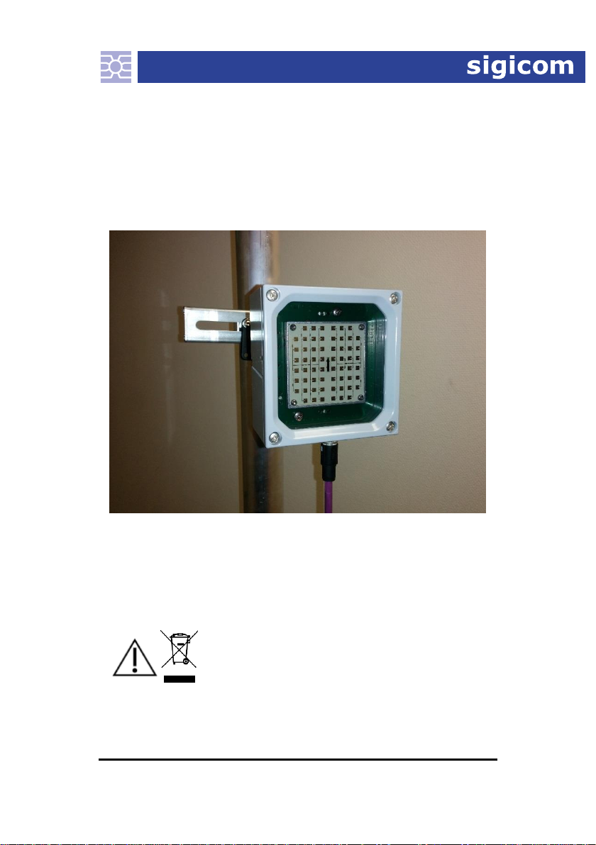
INFRA X20SR
Speed Radar
Art no. 080-03250-0
Manual ver. A Valid for firmware version 1.1.0
Read instructions on safety and electrical equipment waste recycling before
operating this product.

Copyright ©Sigicom AB 2016
1
Developed and manufactured by:
Sigicom AB
Alfred Nobels Allé 214
SE –146 48 Tullinge, Sweden
IMPORTANT SAFETY INSTRUCTIONS –
read this before use.
Workplace hazards:
This equipment will be installed close to rail and road
traffic, which is hazardous workplace. It is very important
to investigate for regulations in respect of risk assessment,
formal personal education demands, authorization etc.
before installation of the equipment.
Operating conditions:
This equipment is designed for outdoor use and wet
locations, but is not immersible. It is designed according to
IEC60529 IPX7.
Temperature range for full functionality is -20 to +50 ºC
(-4 to +122 ºF).
Others:
Do never attempt to disassemble the instruments.
Do never attach your X20SR to any other system or current
source than cables and units within the INFRA Field
Monitoring System.
The radar module used is third party certified to ETSI EN
300 440-2. Its output power is max 20dBm EIRP straight
ahead of the unit at 1% duty cycle. This leads to an average
output power of approximately 1mW strait ahead of the
unit, which can be considered as safe for all living
creatures.

2 Copyright ©Sigicom AB 2016
This equipment falls under the Waste Electrical and Electronic
Equipment Directive (WEEE directive) 2002/96/EC with its last
update 2009, category 9: monitoring and control instruments:
Scrapped equipment should be sent back to the manufacturer of
the equipment (Sigicom) for proper handling according to the
WEEE directive.
Sigicom’s partner for recycling of scrapped equipment is Hans
Andersson Recycling Stockholm AB, with transport certificate
no. 562-1372-2012 (Länsstyrelsen i Stockholms län).

Copyright ©Sigicom AB 2016
3
Table of Contents
1 Introduction.....................................................................................4
1.1 About this manual.............................................................4
1.2 Unpacking and Parts Identification ..................................5
2General description ....................................................................6
3Design features...........................................................................7
3.1 Quantities..........................................................................7
3.2 Display devices.................................................................7
4Configuration and operation ......................................................8
4.1 Mounting ..........................................................................8
4.2 Lobe................................................................................10
4.3 Range..............................................................................11
4.4 Angle error correction ....................................................11
4.5 Mounting check..............................................................12
4.6 Parameters ......................................................................13
4.7 Quick start ......................................................................14
4.8 Error indication...............................................................15
4.9 LED indications..............................................................15
5Maintenance and calibration ....................................................16
6Accessories ..............................................................................17
6.1 Other accessories....................................................................17
7Contact and support .................................................................18
Appendix A......................................................................................19
A.1 Power consumption...............................................................19
A.2 Mechanical data ....................................................................19

4 Copyright ©Sigicom AB 2016
1 Introduction
1.1 About this manual
This manual covers the following topics:
Chapter 1 –Introduction: Some introductory information
about unpacking and safety.
Chapter 2 –General description. An overview of X20SR
and the INFRA Field Monitoring System.
Chapter 3 –Design features: An overview of the measured
quantities. Gives also introduction to display devices within
INFRA.
Chapter 4 –Configuration and operation: Mounting
description and a detailed description of X20SR’s standards
and parameter settings. It also includes a Quick start guide.
Chapter 5 –Maintenance information.
Chapter 6 –Accessories: Lists the accessories for X20SR,
and X20SR-related accessories for the INFRA Field
Monitoring System.
Chapter 7 –Contact and support. Contains contact
information to Sigicom AB.

Copyright ©Sigicom AB 2016
5
1.2 Unpacking and Parts Identification
Your X20SR Speed Radar has been shipped in protective packaging.
Please verify the package content with the following list:
INFRA X20SR Speed Radar Unit
Please report any damage or shortage immediately to Sigicom.
Record the instrument’s serial number. You will be asked to give this
number in any X20SR related communication you may have with
Sigicom.

6 Copyright ©Sigicom AB 2016
2General description
The INFRA X20SR Speed Radar is designed for speed
measurements of different types of vehicles. Speeds up to 250 km/h
can be measured with 2 km/h resolution, both moving towards and
away from the unit.
The X20SR uses a high quality Doppler radar module, working in
the K-band (24.15GHz ISM Band). Dual channel techniques and
advanced signal processing makes it possible to distinguish between
movements toward and away from the unit, as well as filter out false
moving objects.
The X20SR continuously calculates speeds in both directions. At the
end of each interval it selects the direction seen the largest reflected
signal level to represent the interval. Movements toward the unit are
presented as positive values and movements away from the unit are
presented as negative values.
All quantities that are measured by your system are synchronized,
and can be viewed in any of the INFRA presentation systems.
The X20SR Speed Radar shall be connected to the INFRA Field
Monitoring System by any of the available INFRA Sensor Cables,
which:
Supplies the X20SR with electrical power
Handles the communication with the Datalogger, which is
the main unit in the INFRA Field Monitoring System.
Within INFRA Field Monitoring System it is possible to measure a
number of other quantities simultaneously with the speed
measurements, for example:
vibration (geophone) in one direction
vibration (geophone) in three directions
sound level
air blast
dust concentration

Copyright ©Sigicom AB 2016
7
3Design features
3.1 Quantities
Speed: Maximum speed with direction indicated as its sign measured
in kilometers per hour [km/h]. Calculation, which is over the selected
interval time, is made inside the X20SR.
3.2 Display devices
Your X20SR Speed Radar shall be connected to the INFRA Field
Monitoring System. Preferably use INFRA Net to display your
recorded measurements.
It is also possible to view the latest saved value and live values in the
Datalogger display.

8 Copyright ©Sigicom AB 2016
4Configuration and operation
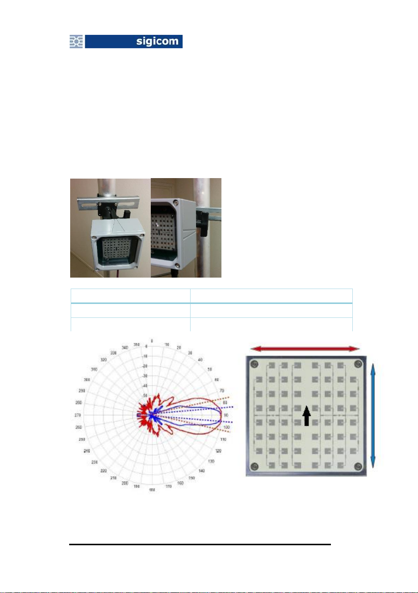
4.1 Mounting
Mounting the X20SR unit correctly is very critical for achieving
acceptable results, or even results at all. The unit needs to be firmly
mounted (when measuring), especially if measuring close to the rail.
Preferably use a stable pole combined with proper mounting details,
as shown below for mounting of the unit.
The unit has a RAM Mount ® 1.5” RAM Ball Base attached to its
back side. RAM Mount products is widely available over the world.
See http://www.rammount.com/partners.
Example: http://www.ram-mount.se/ram-202u-225.html , often with
parts in stock.
Pole mounts: http://www.rammount.com/part/RAM-235U and
http://www.rammount.com/part/RAM-118BU
Double socket arm: http://www.rammount.com/part/RAM-201U-B

Copyright ©Sigicom AB 2016
9
See http://www.rammount.com/part/RAM-202U-225 as an entry for
suitable mounting accessories, or
http://www.rammount.com/components/1.5?query=1.5 for all 1.5”
accessories.
For rail vehicle measurements it is recommended to position the
radar 5-10 meters from the rail and direct the radar sideways so that
it aims to (the center of) the rail 40-70 meters away. The radar
should be approximately 1.5 meter above the rail level and
horizontally aligned with good precision, using a spirit-level is
recommended.
For road vehicle measurements the height level above the road is
recommended to be 0.6 –0.8 meter to be able to catch all standard
sized cars.
10 Copyright ©Sigicom AB 2016
4.2 Lobe
The measurement lobe is narrow, this means that the radar will have
to be very exactly pointing to the object of measurement. The lobe
has different width depending on its alignment. It is recommended to
mount the radar so that the lobe is wide in the horizontal plane for
measurements on fast vehicles.
The lobe widths are indicated on the case of the unit.
Lobe
Blue
12 deg (±6 deg from center line)
Red
24 deg (±12 deg from center line)

Copyright ©Sigicom AB 2016
11
4.3 Range
The range differs depending on a number of factors, keeping within
70 meters from objects have been successful in field tests.
4.4 Angle error correction
Depending on how the radar is mounted there might be need for
certain correction on the measured speed due to the angle in which
the radar measures. If following the recommendations in this
manaual, the correction due to radar position and direction will be
minimal.
Radar setup, v can be either positive or negative.

12 Copyright ©Sigicom AB 2016
Correction factors for different radar placement setups.
Distance L
[m]
Correction
factor C
for d= 5 [m]
Correction
factor C
for d= 10
[m]
Correction
factor C
for d= 20*
[m]
40
1.008
1.031
1.118**
50
1.005
1.020
1.077**
60
1.004
1.014
1.054**
70
1.003
1.010
1.040**
* not recommended distance
** measurement errors larger than 3.5% due to radar placement
The radar placement will be a problem if the distance dis long and
distance Lis short, a potential problem could appear if being unable
to setup the radar with a short distance dto the rail. As seen in table
above, this is simply fixed by directing the radar further down the
rail (increase L). But then the total range of the radar might become
an issue instead.
In such a situation, a rule of thumbs could be to assure that
70m > 𝐿 > 4𝑑
in order to secure measurements with less than 3.5% error due to
radar placement.
4.5 Mounting check
It is recommended (if possible) to check the setup functionality after
mounting. This is easiest done by waiting for the passage of a
vehicle, then read “LAST value” values from the logger during or
directly after the passage. 5 seconds interval time is recommended
for the test.
By continuously pressing “F2” the last interval value will show in
the display, until it is replaced by a new one. If a reasonable value is
shown when a vehicle is passing by then the unit is set up properly.

Copyright ©Sigicom AB 2016
13
4.6 Parameters
The parameters described below are normally set using the user
interface of the Datalogger. However, some parameters are also
possible to set in INFRA Net (Remote control).
4.6.1 Standards
X20SR Speed Radar has only one standard
1
.
S01 (SR km/h):
Top speed during interval measured in kilometers per hour [km/h], the
resolution is 2 km/h.
4.6.2 Interval time
The interval time is how often the measured speed value is
registered. The minimum interval time is 5s.
4.6.3 Threshold levels
No threshold levels can be set for the INFRA X20SR unit.
4.6.4 Customer string
The customer string is a four character string that can be changed.
The default string is “SR “.
1
The word standard means for X20SR the measured quantity and its unit.

14 Copyright ©Sigicom AB 2016
4.7 Quick start
1. Connect your X20SR Speed Radar with your INFRA
Datalogger (Master, Mini or Micro) by using any of the
available INFRA Sensor Cables.
2. Start the Datalogger and wait for initialization process to be
finished.
3. Under the menu Nodes you’ll find your SR unit as
SR X20SR-<serial no.>,
where SR is the customer string and <serial no.> is the serial
number.
4. Check and make necessary changes of its setup.
5. Activate REG ON, and the measurement will be initiated.

Copyright ©Sigicom AB 2016
15
4.8 Error indication
If the speed radar malfunctions, the Datalogger displays “Node lost”
after about two minutes.
4.9 LED indications
An upper-middle red flash is shown when each interval is
saved.
A lower-right green LED is lit when an object is detected.

16 Copyright ©Sigicom AB 2016
5Maintenance and calibration
Send the device to Sigicom for calibration and
adjustment. See contact information below.
Recommended calibration interval is 12 months.
If sent to repair, please carefully write down the
description of the problem. It is also recommended
contacting Sigicom before sending the unit for
repair.

Copyright ©Sigicom AB 2016
17
6Accessories
The X20SR has a RAM Mount ® 1.5” RAM Ball Base attached to
its back side. RAM Mount products is widely available over the
world. See http://www.rammount.com/partners.
6.1 Other accessories
Accessories suitable for the X20SR when connecting it to the
INFRA Field Monitoring System:
Drop cables in selected lengths
Bus cables in selected lengths
Bus cables in special lengths on special order, please contact
Sigicom.
Self-vulcanizing tape, art.no 080-01892-0
Window feed through cable, art.no 080-01472-0
T-port, art.no. 080-01230-1
Termination plug, art.no 080-01236-0
Desiccant bags for INFRA dataloggers
Lockable wall mounts
Tool kits
CompactFlash cards and USB reader
RS232 cables and USB adapter
Spare batteries
External modems for INFRA Micro
Packaging boxes and material
See latest INFRA product catalogue for a complete list of accessories
and more details.

Copyright ©Sigicom AB 2016
19
Appendix A
A.1 Power consumption
During measuring X20SR Speed Radar consumes approximately
320mW.
A.2 Mechanical data
Housing protection class
IPx7
Weight (with ball base)
890 g (2.0 lbs)
Table of contents
Popular Radar manuals by other brands


Axis
Axis D2210-VE installation guide

Emerson
Emerson Rosemount 5300 Series Reference manual

Carmanah
Carmanah SpeedCheck-15 install guide

Kustom Signals
Kustom Signals Eagle 3 North Carolina Quick reference guide

Smiths
Smiths Kelvin Hughes Nucleus 3 Series System handbook

Telephonics
Telephonics RDR-1600 installation manual

Radiodetection
Radiodetection RD8000 Quick Locating Guide

Carmanah
Carmanah SpeedCheck-15 install guide

Endress+Hauser
Endress+Hauser PROFIBUS PA Micropilot FMR56 Brief operating instructions

Blackbe;rry
Blackbe;rry ITC100-1 installation guide

Teledyne
Teledyne FLIR Elara R Series Quick install guide

Endress+Hauser
Endress+Hauser HART Micropilot S FMR533 Brief operating instructions