Acconeer A111 User manual

A111 –Pulsed Coherent Radar (PCR)
Datasheet v1.8

A111 Pulsed Coherent Radar (PCR)
Datasheet, v1.8
© 2019 Copyright by Acconeer 2019-06-12 Page 2 of 34
Features
•Fully integrated sensor
-60 GHz Pulsed Coherent Radar (PCR)
-Integrated Baseband, RF front-end and
Antenna in Package (AiP)
-5.5 x 5.2 x 0.88 mm fcCSP, 0.5 mm pitch
•Accurate distance ranging and movements
-Measures absolute range up to 2 m (1)
oAbsolute accuracy in mm
-Relative accuracy in µm
-Possible to recognize movement and
gestures for several objects
-Support continuous and single sweep
mode
-Continuous sweep update rate up to
1500 Hz (2)
-HPBW of 80 (H-plane) and 40 degrees
(E-plane)
•Easy integration
-One chip solution with integrated
Baseband and RF
-Can be integrated behind plastic or glass
without any need for a physical aperture
-Single reflowable component
-1.8 V single power supply, enable with
Power on Reset (PoR)
-Clock input for crystal or external
reference clock, 20-80 MHz
-SPI interface for data transfer, up to 50
MHz SPI clock support
-INTERRUPT support
A111 Overview
The A111 is a radar system based on pulsed
coherent radar (PCR) technology and is setting a
new benchmark for power consumption and
distance accuracy –fully integrated in a small
package of 29 mm2.
The A111 60 GHz radar system is optimized for
high precision and ultra-low power, delivered as a
one package solution with integrated Baseband,
RF front-end and Antenna in Package (AiP). This
will enable easy integration into any portable
battery driven device.
The A111 is based on leading-edge patented
sensor technology with pico-second time
resolution, capable of measuring absolute
distance with mm accuracy up to a range of
2 m (1) and with a continuous sweep update
frequency fully configurable up to 1500 Hz (2).
The A111 60 GHz radar remains uncompromised
by any natural source of interference, such as
noise, dust, color and direct or indirect light.
Applications
•High precision distance measurements with
mm accuracy and high update frequency
•Proximity detection with high accuracy and
the possibility to define multiple proximity
zones
•Motion detection, Speed detection
•Enables material detection
•High precision object tracking, enabling
gesture control
•High precision tracking of 3D objects
•Monitor vital life signs such as breathing and
pulse rate
(1) 2m ranging is guaranteed for an object size, shape and dielectric properties corresponding to a spherical corner reflector of 5 cm radius.
(2) System integration dependent –e.g. Host MCU and SPI performance.

A111 Pulsed Coherent Radar (PCR)
Datasheet, v1.8
Page 3 of 34 2019-06-12 © 2019 Copyright by Acconeer
Table of Contents
1Revision History........................................................................................................................................... 4
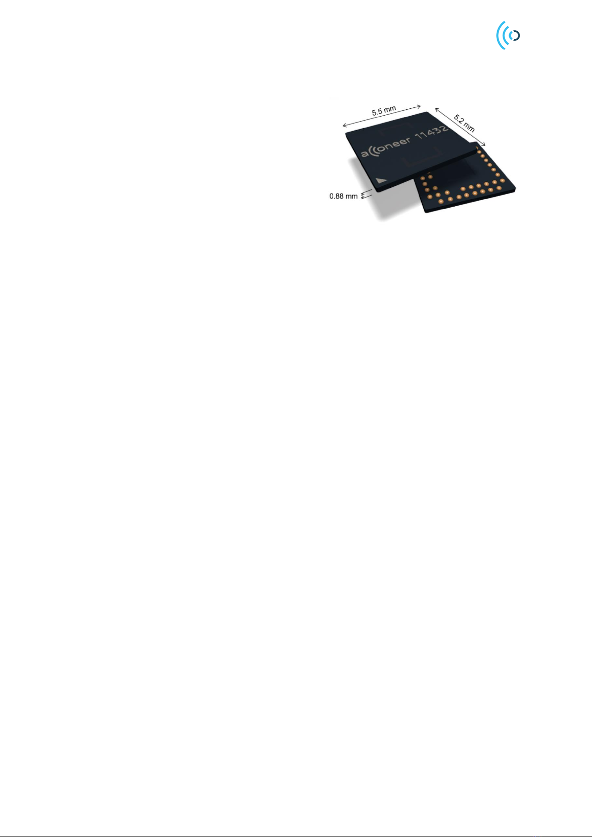
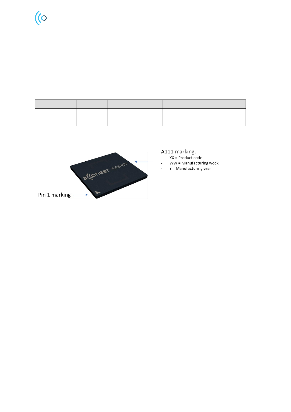
2Description.................................................................................................................................................... 5
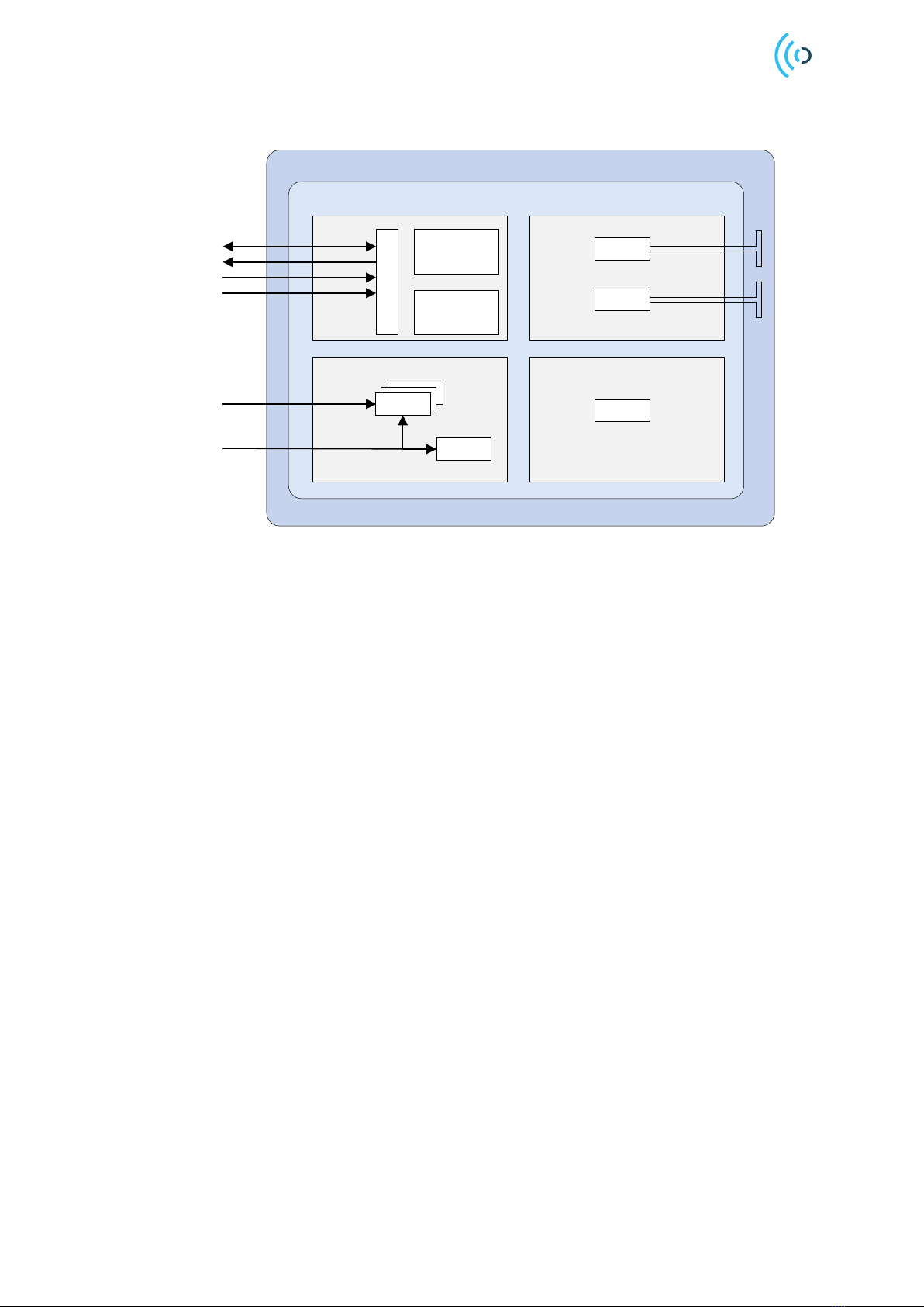
2.1 Functional Block Diagram.................................................................................................................. 6
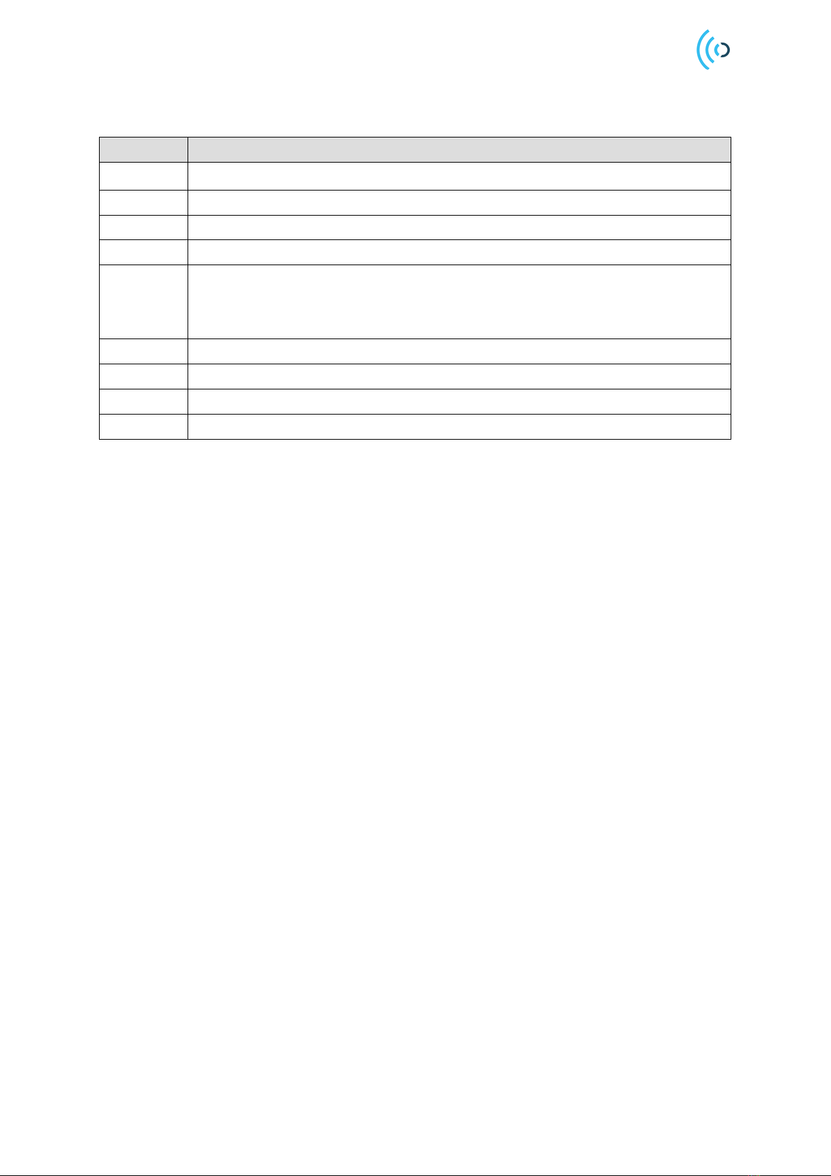
3Pin Configuration and Functions............................................................................................................... 7
4Specifications............................................................................................................................................... 9
4.1 Absolute Maximum Ratings............................................................................................................... 9
4.2 Environmental Sensitivity................................................................................................................... 9
4.3 Recommended Operating Conditions............................................................................................ 10
4.4Electrical Specification ..................................................................................................................... 10
4.5 Power Consumption Summary....................................................................................................... 11
4.6 RF Specification................................................................................................................................ 11
5Timing Requirements.................................................................................................................................12
5.1 Serial Peripheral Interface............................................................................................................... 12
6Typical Characteristics...............................................................................................................................14
6.1 Distance Accuracy............................................................................................................................ 14
6.2 Amplitude Accuracy.......................................................................................................................... 15
6.3 Relative Phase Accuracy................................................................................................................. 15
6.4 Half Power Beamwidth (HPBW)..................................................................................................... 16
7Functional Description ...............................................................................................................................17
7.1 Acconeer Software ........................................................................................................................... 18
7.2 Software Integration ......................................................................................................................... 18
7.3 Power Up Sequence......................................................................................................................... 19
8Layout Recommendations.........................................................................................................................21
8.1 Bill of Material (BoM)........................................................................................................................ 22
8.2 XTAL................................................................................................................................................... 23
8.3 External clock source....................................................................................................................... 24
8.4 Power supply..................................................................................................................................... 25
9Regulatory Approval...................................................................................................................................27
9.1 ETSI.................................................................................................................................................... 27
9.1.1 EU declaration of conformity ..................................................................................................... 27
9.2 FCC Approval.................................................................................................................................... 28
9.2.1 FCC Regulatory Notes................................................................................................................ 28
9.2.2 FCC Grant Authorization............................................................................................................ 29
10 Mechanical Data.....................................................................................................................................30
10.1 Recommended Reflow Profile ........................................................................................................ 32
11 Abbreviations..........................................................................................................................................33
Disclaimer.............................................................................................................................................................34

A111 Pulsed Coherent Radar (PCR)
Datasheet, v1.8
© 2019 Copyright by Acconeer 2019-06-12 Page 4 of 34
1 Revision History
Revision
Comment
V1.0
Released version
V1.1
Minor reference correction in chapter 5.1. A111 marking info added in chapter 2.
V1.2
Relative phase accuracy added in chapter 6.3
V1.3
Ordering information added in chapter 2. Equation corrected in XTAL chapter 8.1.
V1.4
- EU declaration of conformity added, chapter 9.0.
- Pin configuration alphabetically order corrected, chapter 3.
- Acconeer Software chapter 7.1 updated including updated software
integration info, chapter 7.2.
V1.5
Removed introduced error in chapter 3, pin configuration.
V1.6
FCC modular approval added, chapter 9.2.
V1.7
Power supply specification added, chapter 8.4.
V1.8
Added clarification, section 9.2.

A111 Pulsed Coherent Radar (PCR)
Datasheet, v1.8
Page 5 of 34 2019-06-12 © 2019 Copyright by Acconeer
2 Description
The A111 is an optimized low-power, high-precision, 60 GHz radar sensor with integrated Baseband,
an RF front-end and an Antenna in Package (AIP).
The sensor is based on pulsed coherent radar (PCR) technology, featuring a leading-edge patented
solution with picosecond time resolution. The A111 is the perfect choice for implementing high-
accuracy, high-resolution sensing systems with low-power consumption.
Ordering information
Part number
Package
Size (nom)
Primary component container
A111-001-T&R
fcCSP50
5.2 x 5.5 x 0.88 mm
Tape & reel
A111-001-TY
fcCSP50
5.2 x 5.5 x 0.88 mm
13” Tray
Acconeer A111 marking

A111 Pulsed Coherent Radar (PCR)
Datasheet, v1.8
© 2019 Copyright by Acconeer 2019-06-12 Page 6 of 34
2.1 Functional Block Diagram
A111 One Package Solution
A111 Silicon
TX
RX
PLL
LDOs
PoR
Communication
Program
memory
Data
memory
SPI (4)
INTERRUPT
XIN (ref clk)
XOUT
1.8V Single
power supply
ENABLE
Digital
Power Timing
mmWave Radio Tx ant.
Rx ant.
Figure 2.1. The A111 functional block diagram.
The A111 silicon is divided into four functional blocks: Power, Digital, Timing and mmWave radio.
The Power functional block includes LDOs and a Power on Reset (PoR) block. Each LDO creates its
own voltage domain. The PoR block generates a Reset signal on each power-up cycle. The host
interfaces the Power functional block of the sensor via 1.8V Single power supply and ENABLE.
The Digital functional block includes sensor control. The data memory stores the radar sweep data
from the ADC. The host interfaces the Sensor via an SPI interface, a Clock (XIN, XOUT) and
INTERRUPT signal.
The Timing block includes the timing circuitry.
The mmWave radio functional block generates and receives radar pulses and includes transmitter
(TX), receiver (RX) and interfaces toward the integrated antennas.

A111 Pulsed Coherent Radar (PCR)
Datasheet, v1.8
Page 7 of 34 2019-06-12 © 2019 Copyright by Acconeer
3 Pin Configuration and Functions
The below figure shows the A111 pin configuration, top view:
1
2
3
4
5
6
7
8
9
10
A
NC
B
NC
C
VIO_1a
VIO_2a
GND
D
VIO_1b
VIO_2b
Supply
E
I/O
F
ENABLE
CLK
G
Analog
H
XOUT
NC
J
VBIAS
SPI_SS
VIO_3a
XIN
K
SPI_CLK
SPI_MISO
SPI_MOSI
INTERRUPT
VIO_3b
Figure 3.1. Pin configuration of the A111 sensor, top view.
The below table shows the A111 total number of 50 pins:
Pin
Pin name
Pin type
Description
Comment
A2
NC
Must no connect
A3-A8
GND
Ground
Must be connected to solid ground plane
A9
GND
Ground
Must be connected to solid ground plane
B1
NC
Must no connect
B2, B9
GND
Ground
Must be connected to solid ground plane
B10
GND
Ground
Must be connected to solid ground plane
C1
GND
Ground
Must be connected to solid ground plane
C2
VIO_1a
Supply voltage
Supply voltage, RF part (1)
C9
VIO_2a
Supply voltage
Supply voltage, RF part (1)
C10
GND
Ground
Must be connected to solid ground plane
D1
VIO_1b
Supply voltage
Supply voltage, RF part (1)
D2, D9
GND
Ground
Must be connected to solid ground plane
D10
VIO_2b
Supply voltage
Supply voltage, RF part (1)
E1, E2,
E9, E10
GND
Ground
Must be connected to solid ground plane
F1
GND
Ground
Must be connected to solid ground plane

A111 Pulsed Coherent Radar (PCR)
Datasheet, v1.8
© 2019 Copyright by Acconeer 2019-06-12 Page 8 of 34
Pin
Pin name
Pin type
Description
Comment
F2, F9
GND
Ground
Must be connected to solid ground plane
F10
ENABLE
I/O
Must be connected to host MCU
available GPIO. ENABLE is active high
G1,
G10
GND
Ground
Must be connected to solid ground plane
H1
GND
Ground
Must be connected to solid ground plane
H2, H9
GND
Ground
Must be connected to solid ground plane
H10
XOUT
CLK
XTAL out
No connect
if no XTAL
J1
VBIAS
Analog
The analog VBIAS must be connected to
VIO_3
J2
SPI_SS
I/O
SPI slave select, active low select.
J3, J5,
J6, J8
GND
Ground
Must be connected to solid ground plane
J9
VIO_3a
Supply voltage
Supply voltage, digital part (1)
J10
XIN
CLK
XTAL input OR external ref clk input
1.1V
domain
K2
SPI_CLK
I/O
SPI Serial Clock
K3
SPI_MISO
I/O
Master Input –Slave Output
K4
GND
Ground
Must be connected to solid ground plane
K5
GND
Ground
Must be connected to solid ground plane
K6
SPI_MOSI
I/O
Master Output –Slave Input
K7
GND
Ground
Must be connected to solid ground plane
K8
INTERRUPT
I/O
Interrupt signal, that is used as an
interrupt in the host, more details are
found in section 7, Description.
mandatory
K9
VIO_3b
Supply voltage
Supply voltage, digital part (1)
Table 3.1. A111 sensor pin list
(1) VIO_1a and VIO_1b are short circuit inside the sensor. VIO_2a and VIO_2b are short circuit inside the sensor. VIO_3a
and VIO_3b are short circuit inside the sensor.

A111 Pulsed Coherent Radar (PCR)
Datasheet, v1.8
Page 9 of 34 2019-06-12 © 2019 Copyright by Acconeer
4 Specifications
4.1 Absolute Maximum Ratings
The below table shows the A111 absolute maximum ratings over operating temperature range, on
package, unless otherwise noted:
Parameter
Description
Min.
Max.
Unit
VIO_1 (2)
1.8 V RF power supply
0
2.0
V
VIO_2 (2)
1.8 V RF power supply
0
2.0
V
VIO_3
1.8 V digital power supply
0
2.0
V
XIN (1)
Clock input port for crystal or reference
clock
-0.5
1.6
V
I/O
I/O supply voltage
-0.5
VIO_3+0.5
V
TOP
Operating temperature range
-40
85
°C
TSTG
High temperature storage
150
°C
Table 4.1. Absolute maximum ratings
(1) XIN input may not exceed 0V when ENABLE is low.
(2) VIO_1 and VIO_2 must never exceed VIO_3.
Stresses beyond those listed in table 4.1 may cause permanent damage to the device. These are stress
ratings only and functional operation of the device at these conditions or at any other conditions
beyond those indicated under Recommended Operating Conditions is not implied. Exposure to
absolute-maximum-rated conditions for extended periods of time may affect device reliability.
4.2 Environmental Sensitivity
The below table shows the A111 environmental sensitivity:
Parameter
Standard
Max.
Unit
Storage temperature
JESD22-A103 (1)
150(1)
ºC
Reflow soldering temperature (1)
J-STD-020 (1)
260
ºC
Moisture Sensitivity Level
JESD22-A113 (1)
MSL3
ESD, Charge Device Model (CDM)
JS-002, Class C2
500
V
ESD, Human Body Model (HBM)
JS-001, Class 1C
1000
V
Latch-up
JESD78, Class I
Pass
Table 4.2 Environmental sensitivity
(1) For reference only. The package is generically qualified by the manufacturer. Acconeer does not guarantee adherence to
standard.

A111 Pulsed Coherent Radar (PCR)
Datasheet, v1.8
© 2019 Copyright by Acconeer 2019-06-12 Page 10 of 34
4.3 Recommended Operating Conditions
The below table shows the A111 recommended operating conditions, on package:
Parameter
Min.
Typ.
Max.
Unit
Operating power supply voltage, VIO_1
1.71
1.8
1.89
V
Operating power supply voltage, VIO_2
1.71
1.8
1.89
V
Operating power supply voltage, VIO_3
1.71
1.8
1.89
V
I/O operating range
-0.3
VIO_3+0.3
V
XIN operating range (1)
-0.3
1.2
V
Operating temperature
-40
85
ºC
Table 4.3. Recommended operating conditions
(1) XIN input must not exceed 0V when ENABLE is low.
4.4 Electrical Specification
The below table shows the A111 electrical DC specification conditions, on package, at TA= 25ºC:
Parameter
Min.
Typ.
Max.
Unit
Current into any power supply
100
mA
I/O VIL Low-level input voltage
-0.3
0.10*VIO_3
V
I/O VIH High-level input voltage
0.90*VIO_3
VIO_3+0.3
V
I/O VOL Low-level output voltage
0.4
V
I/O VOH High-level output voltage
1.6
V
I/O IOL (VOL = 0.4V)
7.8
mA
I/O IOH (VOH = VIO_3-0.4)
5.8
mA
I/O IIL Low-level input current
<1
µA
I/O IIH High-level input current
<1
µA
XIN VIL Low-level input voltage
-0.3
0.4
V
XIN VIH High-level input voltage
1.0
1.2
V
XIN IIL Low-level input current
<1
µA
XIN IIH High-level input current
<1
µA
Table 4.4. Electrical DC conditions

A111 Pulsed Coherent Radar (PCR)
Datasheet, v1.8
Page 11 of 34 2019-06-12 © 2019 Copyright by Acconeer
The below table shows the A111 electrical AC specification conditions, on package, at TA= 25ºC:
Parameter
Min.
Typ.
Max.
Unit
I/O output operating frequency
100
MHz
I/O load capacitance
20
pF
XIN operating frequency
20
80(1)
MHz
XIN capacitance
0.2
pF
Table 4.5 Electrical AC conditions
(1) The maximum external reference clock frequency is 80 MHz and the maximum XTAL frequency is 50 MHz.
4.5 Power Consumption Summary
The below table summarizes the power consumption, maximum current ratings and average current
ratings at all power terminals (VIO_1, VIO_2, VIO_3), at TA= 25ºC, VIO 1.8 V:
Parameter
Min.
Typ.
Max.
Unit
Current consumption, continuous TX active mode
71
mA
Average power consumption, 0.1 Hz sweep rate (2)
0.2 (1)
mW
Average power consumption, 10 Hz sweep rate (2)
3 (1)
mW
Average power consumption, 100 Hz sweep rate
20 (1)
mW
Current leakage at ENABLE low
66
µA
Table 4.6. Maximum and Average current ratings at power terminals.
(1) Measuring window set to 0.24 m, configuration with maximize on depth resolution used. Leakage current in ENABLE
low not removed.
(2) Supply voltage turned off in between measurements.
4.6 RF Specification
The below table shows the A111 RF specification:
Parameter
Min.
Typ.
Max.
Unit
Center frequency fc
60.5
GHz
EIRP
10
dBm
HPBW, elevation plane (1)
40
degrees
HPBW, horizontal plane (1)
80
degrees
Update frequency (configurable) (2)
1500
Hz
Table 4.7 A111 RF specification
(1) See chapter 6 Typical Characteristics for elevation (E-plane) and horizontal (H-plane) HPBW.
(2) System integration dependent e.g. Host MCU and SPI performance.

A111 Pulsed Coherent Radar (PCR)
Datasheet, v1.8
© 2019 Copyright by Acconeer 2019-06-12 Page 12 of 34
5 Timing Requirements
5.1 Serial Peripheral Interface
The Serial Peripheral Interface (SPI) is a 4-wire serial bus, used for configuration and reading output
from the A111 radar sensor. The A111 radar sensor is an SPI slave device connected to the SPI
master, as described in figure 5.1. The A111 allows several devices to be connected on the same SPI
bus, with a dedicated slave-select signal. Daisy-chain is not supported.
Host
(SPI Master) A111
(SPI Slave)
A111
(SPI Slave)
SPI_CLK
SPI_MOSI
SPI_SS1
SPI_SS2
SPI_MISO
Figure 5.1. SPI master-slave connection
The serial data transfer input (MOSI) and output (MISO) to the A111 are synchronized by the
SPI_CLK. The Slave Select signal (SS) must be low before and during transactions. The MOSI is
always read on the rising edge of SCLK and the MISO changes value on the falling edge of SPI_CLK
(SPI mode 0, CPOL/CPHA = 0). SS requires release in between transactions. See figure 5.2 and table
5.1 for timing characteristics.
SPI_ClK
MOSI
MISO
SS
SS setup time
MSB
MOSI hold time MOSI setup time MISO propagation delay SS hold time
LSB
15
15 14
14
13
13
0
0
1
1
2
2
Figure 5.2: Timing diagram of SPI, CPOL=0 and CPHA=0.

A111 Pulsed Coherent Radar (PCR)
Datasheet, v1.8
Page 13 of 34 2019-06-12 © 2019 Copyright by Acconeer
Parameter
Min.
Typ.
Max.
Unit
Clock frequency (1)
50
MHz
SS setup time
1.0
ns
SS hold time
2.0
ns
MOSI setup time
1.0
ns
MOSI hold time
2.5
ns
MISO propagation delay (2)
5.5
ns
Table 5.1 SPI timing characteristics
(1) The 50 MHz clock frequency requires that the reference clock is at least 20.625 MHz
(2) 10pF load on SPI_MISO

A111 Pulsed Coherent Radar (PCR)
Datasheet, v1.8
© 2019 Copyright by Acconeer 2019-06-12 Page 14 of 34
6 Typical Characteristics
6.1 Distance Accuracy
Conditions: TA= 25 ºC, VDD = 1.8 V. Statistical result based on sweep count 100, 20 tested devices.
The below figure shows the standard deviation of distance estimation, configuration using envelope
service with maximize depth resolution profile, 0.06-0.30 m. Object metal cylinder, 40 mm in
diameter.
Figure 6.1. Standard deviation of distance estimation, maximize on depth resolution 0.06-0.30 m.
The below figure shows the standard deviation of distance estimation, configuration using envelope
service with maximize SNR profile, 1.76-2.0 m. Object 50 mm radius spherical metal corner reflector.
Figure 6.2. Standard deviation of distance estimation, maximize on SNR 1.76-2.0 m

A111 Pulsed Coherent Radar (PCR)
Datasheet, v1.8
Page 15 of 34 2019-06-12 © 2019 Copyright by Acconeer
6.2 Amplitude Accuracy
Conditions: TA= 25 ºC, VDD = 1.8 V. Statistical result based on sweep count 100, 20 tested devices.
The below figure shows the standard deviation of amplitude estimation, configuration using envelope
service with maximize depth resolution profile, 0.06-0.30 m. Object metal cylinder 40 mm diameter.
Figure 6.3. Standard deviation of amplitude estimation, maximize on depth resolution 0.06-0.30 m.
The below figure shows the standard deviation of amplitude estimation, configuration using envelope
service with maximize SNR profile, 1.76-2.0 m. Object 5 cm radius spherical metal corner reflector.
Figure 6.4. Standard deviation of amplitude estimation, maximize on SNR 1.76-2.0 m.
6.3 Relative Phase Accuracy
Conditions: TA= 25 ºC, VDD = 1.8 V. Statistical result based on sweep count 100, 20 tested devices.
Standard deviation of phase estimation, measured at a distance of 0.35 m. Object metal cylinder, 40
mm in diameter.
Average STD of relative phase estimation:
•6.1 degrees in relative phase accuracy, translates to 42 µm in relative distance accuracy.

A111 Pulsed Coherent Radar (PCR)
Datasheet, v1.8
© 2019 Copyright by Acconeer 2019-06-12 Page 16 of 34
6.4 Half Power Beamwidth (HPBW)
Conditions: TA= 25 ºC, VDD = 1.8 V. Statistical result based on sweep count 100 (20 tested devices).
This section shows the A111 Elevation plane (E-plane) and Horizontal plane (H-plane) radiation
pattern.
The below figure shows the normalized radiation pattern at E-plane, configuration using envelope
service with maximize depth resolution profile, with a 5 cm radius spherical metal corner reflector.
HPBW for E-plane is ±20 degrees, as shown in the below figure.
Figure 6.5. Normalized radiation pattern at E-plane.
The below figure shows the normalized radiation pattern at H-plane, configuration using envelope
service with maximize depth resolution profile, with a 5 cm radius spherical metal corner reflector.
The HPBW for H-plane is ±40 degrees, as shown in the below figure.
Figure 6.6. Normalized radiation pattern at H-plane

A111 Pulsed Coherent Radar (PCR)
Datasheet, v1.8
Page 17 of 34 2019-06-12 © 2019 Copyright by Acconeer
7 Functional Description
The below figure shows the A111 system integration with Host MCU:
Host MCU A111
Sensor
TCXO
ENABLE x1
SPI x4
INTERRUPT x1
1.8V single power supply
CLK ref. 20-80 MHz
Figure 7.1. System integration
The Acconeer software is executed on Host MCU that handles sensor initiation, configuration, sweep
acquisition and signal processing.
The Serial Peripheral Interface (SPI) is a 4-wire serial bus, used for configuration and reading output
from the A111 radar sensor. The A111 radar sensor is an SPI slave device, connected to the SPI
master (Host MCU), and allows several devices to be connected on same SPI bus, with a dedicated
slave-select signal. Daisy-chain is not supported.
The sensor provides support for ENABLE and INTERRUPT as interrupt signal, always output, that is
used as an interrupt in the Host MCU.

A111 Pulsed Coherent Radar (PCR)
Datasheet, v1.8
© 2019 Copyright by Acconeer 2019-06-12 Page 18 of 34
7.1 Acconeer Software
The Acconeer software has been written in C and is portable to any OS and HW platform. The
Acconeer software is executed on Host MCU and delivered as binaries, except for integration software
that is delivered as source code.
The below figure shows the A111 software offer.
Figure 7.2. Acconeer Software offer
The RSS (Radar System Software) provides output at two different levels, Service and Detector. RSS
provides an API (Application Programming Interface) for Application utilization of various Services
and Detectors.
The Service output is pre-processed sensor data as a function of distance E.g. Envelope data
(amplitude of sensor data), Power bin data (integrated amplitude data in pre-defined range intervals),
IQ modulated data (representation in cartesian) etc.
Detectors are built on Service data as input and the output is a result E.g. Distance detector that
presents distance and amplitude result based on envelope Service etc.
Customer can either use Acconeer detector or develop their own signal processing based on Service
data.
Acconeer provides several example applications to support customer own application development.
Also, customer guidelines are provided for application development utilizing the Acconeer RSS API.
Acconeer provides several reference drivers as source code, e.g. Support for Cortex M4, Cortex M7
MCU’s.
7.2 Software Integration
Integration software shall implement functions defined in a definitions file provided in Acconeer
Software offer. This includes handling of SPI, ENABLE and INTERRUPT as well as potential OS
functions.
See reference HAL - User Guide for guideline on software integration and HAL implementation
(https://www.acconeer.com/products).

A111 Pulsed Coherent Radar (PCR)
Datasheet, v1.8
Page 19 of 34 2019-06-12 © 2019 Copyright by Acconeer
7.3 Power Up Sequence
The power-up sequence is described using the recommended integration shown in the below figure:
A111
INTERRUPT
SPI_SS
SPI_MISO
SPI_MOSI
SPI_CLK
ENABLE
VIO_1a,b
VIO_2a,b
VIO_3a,b
VBIAS
XIN
XOUT
GNDs
R1
1.8V
X1
C8C7
R2 C4
C1 C5
C2 C6
C3
Host
Figure 7.3. Recommended integration of the A111 radar sensor.
The power up sequence is shown in below figure.
Time
VIO_1-3a,b
ENABLE
t1t2
XIN
Figure 7.4. Power up sequence

A111 Pulsed Coherent Radar (PCR)
Datasheet, v1.8
© 2019 Copyright by Acconeer 2019-06-12 Page 20 of 34
It is recommended to allow the supply voltage on the sensor to stabilize before activating ENABLE.
That is shown as the time t1in figure 7.4 and the actual time depends on the power supply and the
value of the decoupling capacitors.
Next step in the power up sequence is to have a settling time for the XTAL oscillator to stabilize,
shown as time t2in figure 7.4. This may take up to several milliseconds depending on the XTAL
performance. The sensor does not require any settling time if it is integrated using an external
reference clock. It is advised to have the clock inactive at 0 V while ENABLE is inactive.
Now the A111 radar sensor is ready for SPI communication. All I/Os must never exceed VIO_3
voltage, accordingly if VIO_3 voltage is set to 0V between sensor usage then all I/Os must also be set
to 0V. Otherwise, the internal ESD protection diodes will draw current from the I/O source.
After power up is complete, the sensor is loaded with a program. Up until the point where the sensor’s
program is started, the INTERRUPT is high impedance. However, after the sensor’s program has
started the INTERRUPT is configured to a push-pull CMOS output. Therefore it is required that the
host I/O is configured as input before any programs are started on the sensor.
The power down sequence is recommended to be executed in the reverse order as the power up
sequence: First ensure that all I/O inputs are at 0V which includes ENABLE, after that all VIO1_3a,b
can be turned off.
VIO_1 and VIO_2 must never have higher voltage than VIO_3, and it is recommended to
enable/disable the three supplies simultaneously.
External clock reference, if used, needs always to be available to sensor.
Other manuals for A111
2
Table of contents
Other Acconeer Radar manuals
Popular Radar manuals by other brands

Endress+Hauser
Endress+Hauser Micropilot FMR51 operating instructions

Endress+Hauser
Endress+Hauser Levelflex FMP51 Brief operating instructions

NSR Marine
NSR Marine NRT-1000 user manual

ImpulseRadar
ImpulseRadar PinpointR user manual

Cub
Cub B122-036 user manual

SYMEO
SYMEO LPR-1DHP-200 Series Product documentation