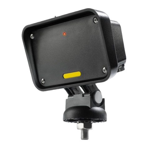
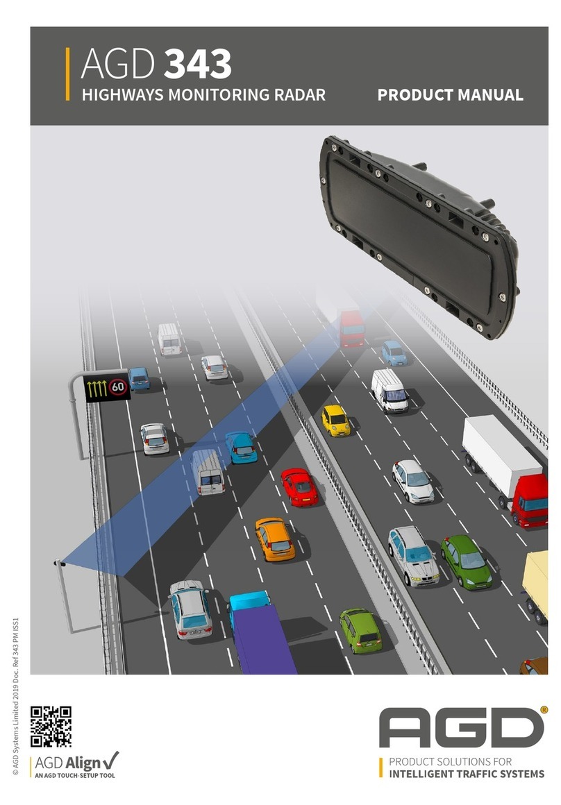
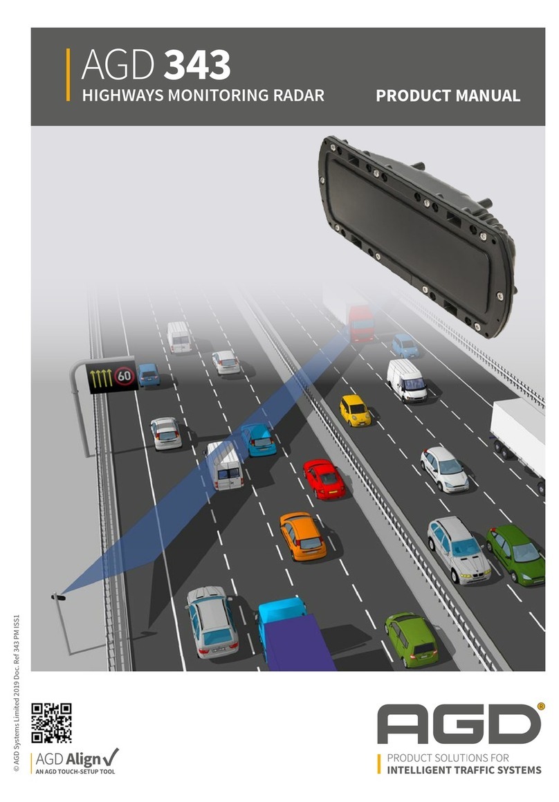
AGD 340 User manual

ISO 14001
Registered
Environmental
Management015
ISO 9001
Registered
Quality
Management015
PRODUCT MANUAL
©AGD Systems Limited 2016 Doc. Ref. 340 PM ISS2

2
INTRODUCTION
Product & technology 3
Key features 3
Typical applications 4
Product overview 4
INSTALLATION
Radar installation & alignment 5-6
SYSTEM HARDWARE OVERVIEW
System hardware overview 7
RS422 serial interface 8
Temperature sensor 8
Non volatile memory 8
Power supply 9
Input protection 9
Radar connectors 9
IQ internal connectors 10
Hardware simulated target 10-11
Overview 12
Tasks 12
Detection task 13-14
Target tracking 15-16
Radar characteristics 17
Radar performance 18-19
RADAR COMMANDS
Radar Command list 20-22
25KHz reference signal & the *FE command 23
Radar initialisation 23
MESSAGE FORMATS
Radar event messages 24-28
Radar status messages 29-35
Radar Error messages 36
ANTENNA PLOTS 37
TECHNICAL SPECIFICATIONS
Product specification 38
TEST & CALIBRATION
Dedicated test equipment 39
MANUFACTURING TEST PROCESS
Hyperion Test Equipment 40
IMPORTANT SAFETY INFORMATION
Safety precautions 41
Low power non-ionising radio transmission and safety 42
CERTIFICATION 43-45
DISCLAIMER 48
Warranty 48
TABLE OF CONTENTS

3
INTRODUCTION
PRODUCT & TECHNOLOGY
KEY FEATURES
• Market leading speed measurement Doppler vehicle radar
• Speed measurement from 20kph to 300kph across multiple lanes
• Custom designed planar antenna
• Ease of integration into host system
• High speed RS422 serial communications to host equipment
• Can discriminate between approaching and receding traffic
340
This product has been designed specifically
to measure the speed of passing vehicles for
enforcement purposes. The 340 CW Doppler
radar operates in the K-band at 24GHz. It is suitable
for many national requirements.
• Vehicle speed enforcement radar detection
• Technically advanced detection platform
• Fixed and mobile deployment options
• Proven reliability

4
INTRODUCTION
TYPICAL APPLICATIONS
Speed enforcement radar traffic detection - approaching Speed enforcement radar traffic detection - receding
PRODUCT OVERVIEW
Tripod mounting point
Flange mounting points
Status LED
Power/Test
connector
RS422 Data
connector

5
INSTALLATION
RADAR INSTALLATION & ALIGNMENT
For best detection performance
the radar must be setup correctly.
Failure to do so can result in
inaccurate or false detections.
Radar Mounting Angle
Radars are supplied factory
programmed to be used for a
specific mounting angle, usually to
22 degrees. This angle is the angle
the radar points across the road
from the direction of the road, see
diagram below. The angle a radar
is setup for is printed on the top
side of the radar. The angle is also
reported in valid detect messages
and the command *AD may be
used to determine it. This angle
is used by the radar to adjust the
speed the radar measures to the
actual target speed and therefore
it is important the radar is setup
with the correct angle. If the radar
is setup with an angle that is less
than the mounting angle then the
radar will measure speeds that are
larger than the vehicles true speed,
while if the angle is greater than
the mounting angle the radar will
measure speeds that are less than
the vehicles true speed.
The radar transmits a radio
beam across the road that has a
horizontal beam width of
~5 degrees. The vertical beam
width of the radar beam is
relatively large at 15degrees so
although the radar should be made
level this is not crucial for correct
operation. For a fixed camera
installation often the radar is
mounted relatively high (~3m) and
in this case it is desirable to point the radar more down towards the ground. In
this application careful consideration of the radar beam and its shape is required
to ensure that all the lanes of the road are covered.
22º
Radar
Offset
342 Beam Analysis
shown assumes;
Mounting Height: 4m
Mounting Angle: 7.5˚
below horizontal
Targets: vehicle reflection
from a height of 1m

6
INSTALLATION
RADAR INSTALLATION & ALIGNMENT
Sensitivity Level
The radar has two sensitivity levels to allow it to
operate in most situations. The sensitivity level is
adjusted using the *SL command. If the radar is being
used to monitor only two lanes of a road then the low
sensitivity level should be chosen. This is particularly
important in an urban environment where the radar
may pick up reflections and falsely trigger the camera
that will take a picture of a non-existent or incorrect
vehicle. This is illustrated opposite where the radar
has triggered the camera because it has detected a
speeding car from its reflected signal off a building.
By setting the sensitivity level of the radar to low, this
weak reflected signal is often not detected.
High sensitivity false detections in an urban environment
To reduce further the possibility of detecting reflections the radar should not be pointed at any large vertical flat
surfaces which may reflect the radars transmissions. This is particularly true if the surface is metal.
When the radar is monitoring 3 or more lanes the high sensitivity mode of the radar maybe used. The radar,
even in low sensitivity mode, will detect most vehicles on a four lane road but some targets with small radar
signal returns may not be detected in the far lanes e.g. motorcycles.
Dual Direction Mode
The radar can be set in a mode to detect speeding vehicles travelling in both directions. This is possible because
the radar has a very good direction sensing capability that allows it to detect vehicles travelling in both directions
at the same time as long as they have different speeds. Each direction is tracked totally independently. In this
mode the vehicle travelling on the opposite side of the road may not be detected correctly because the signal is
blocked by a vehicle nearer to the radar. It is therefore recommended that the radar is setup to detect vehicles
on the far side of the road using beam entry messages and nearby targets using the beam exit messages. The
diagram below shows what can happen in an incorrect setup. In an incorrect setup the vehicle in the far lane is
detected correctly and a beam entry message is sent. This message would not be used to take a photo though
as the rear number plate cannot be seen yet. However, moments later a car travelling in a lane nearer to the
radar blocks the signal from the far vehicle and so the radar sends a beam exit message and the system would
then take a photo. However the far vehicle is not in view and therefore no conviction can be made. In the correct
setup though as soon as the radar detects the speeding far vehicle a beam entry message is sent and a photo
is taken, although the vehicle will still have to be in the beam for a significant amount of time so that it is not
rejected for being too short a vehicle. Moments later the near vehicle blocks the signal from the far target and
a premature beam exit message is
sent but a photo has already been
taken and a safe conviction may
be made. Note in this mode it is
possible for the target messages
to be interleaved between each
other when targets are travelling in
the beam at the same time but in
different directions.

MC-104
CB206
CB192
7
SYSTEM HARDWARE OVERVIEW
DSP
SDRAMBoot Flash
Main Flash
LEDs
Temperature
Sensor
EEPROM
FIFO CPLD
ADC
ADC
UART
RS422

8
SYSTEM HARDWARE OVERVIEW
RS422 SERIAL INTERFACE
A UART interface is provided using RS422 voltage levels. The default baud rate for this interface is 115200. This
however maybe changed using the BAUD command to speeds of up to 926000. The BAUD command will store
the baud rate into non-volatile memory of the radar ready for the next time the radar boots. When the radar first
boots it will always use a baud rate of 115200 to report the radar firmware version and the baud rate that will be
used. It then switches to the new baud rate and again reports the radar firmware version.
The serial interface default setup during normal operation is shown in table below.
The RS422 provides the primary output of the radar in the form of ASCII messages.
These messages provide speed, beam entry and beam exit information.
The externally visible LED is used to indicate the radar status, see table below.
TEMPERATURE SENSOR
A digital temperature sensor has been installed on the digitiser board. This will be used to allow the processor to
monitor environmental conditions. The temperature of the radar may be requested using the TEMP command.
NON VOLATILE MEMORY
An EEPROM is installed on the board to provide non volatile memory. The primary use of this EEPROM is to
store configuration and calibration data.
DEFAULT UART SETTINGS
Parameter Value
Baud rate 115200
Data bits 8
Parity bits None
Stop bits 1
Flow control None
LED STATUS
LED on time (seconds) LED off time (seconds) Radar condition
3 0.5 Normal operation
0.5 0.5 Error condition

9
SYSTEM HARDWARE OVERVIEW
POWER SUPPLY
The radar is powered using a DC voltage in the range of 9 to 30 volts. The radar is polarity protected using
a diode. The radar can draw a very large current doing power up that is of the order of amps. However, this
current only lasts for ~1ms and should not affect most applications.
The power connector is a Bulgin PX0412/03P. (Mating Type PX0410/03S/5560 is recommended)
INPUT PROTECTION
A thermal fuse with a 630mA rating has been installed to protect against electrical short circuit fault conditions.
RADAR CONNECTORS
The data connector is a Bulgin PX0412/08P. (Mating Type PX0410/08S/6065 is recommended)
DATA CONNECTOR
Pin No Signal Description
1A (RX +)
RS422
2B (RX -)
3Z (TX-)
4Y (TX+)
5Do Not Connect This is used for a test signal – do not connect
6Reference Oscillator 24992.54Hz ±50PPM
70V Ground
8spare This pin is not fitted to the bulkhead connector
POWER CONNECTOR
Pin No Signal Description
L +ve Supply 9 to 30V DC
N -ve Supply 0V or Ground
E Earth

10
SYSTEM HARDWARE OVERVIEW
IQ INTERNAL CONNECTORS
The internal connectors J1 and J2 can be used to monitor the in phase and quadrature signals from the
microwave front end. The radar has to be opened to access these connectors and should therefore only be
performed at calibration time. If using an oscilloscope to observe these signals it should be configured as a high
impedance probe. Using a 50Ohm probe to monitor these signals will distort the measurements.
The internal connectors J1 and J2 can be used to inject I and Q signals into the radar. A low impedance source
should be used to provide the signals with a magnitude of up to 5V peak to peak.
HARDWARE SIMULATED TARGET
The radar has a built in hardware based target simulator. This is used during boot up to simulate an approaching
and then a receding target. If an error is detected in the simulated target’s speed then the radar will send an
error message and turn off the ADC clock rending the radar inactive. The radar can be made to perform a
simulated target test at any time by sending a SELF-TEST command. Again if an error is detected in the targets
speed the radar will stop. To distinguish real targets from simulated targets the radar inserts an X or a Y in the
direction fields of all related messages produced. During simulation the microwave front end is turned off to
avoid any possible interference with the simulation.
The CPLD on the digitiser board generates the signals used for the simulated target. These signals are
generated using the logic shown in the diagram. The input signals to the logic are:
• DIR
This input selects the direction the simulated circuit will simulate. This signal is controlled by the
C6711 processor.
• CS
This input selects whether the outputs are active. This signal is controlled by the C6711 processor.
• CLK
This signal is taken from the ADC sample clock and is the circuits input clock.
The purpose of this logic is to generate two square waves, I and Q, with a frequency that is one sixteenth of the
ADC sample frequency (ie 49985.08475 / 16 = 3124.07Hz) and out of phase by 90O. This effectively provides a
simulation of the expected signals from the microwave module when it can see a Doppler target. The DIR signal
controls whether the Q channel lags or leads by 90º and therefore controls the effective direction the simulated
target is travelling.

11
SYSTEM HARDWARE OVERVIEW
The I and Q signals from the CPLD are then filtered before being applied to the –ve input of the digitisers board
input operation amplifiers. The filter reduces the harmonic content of the I and Q signals to a level which the
radar can cope with.
FD
FD
D
D
Q0
Q1
CEO
TC
CE
C
Q
Q
C
C
CB2RE
FD
D Q
C
R
I
Q
CLK/2
CLK/2
DIR
CE
AND2B2
AND2
QR2
QR2
AND2B1
AND2B1
GND
INV

12
SYSTEM HARDWARE OVERVIEW
OVERVIEW
The AGD340 radar is a real time radar that continuously samples the input. The radar uses a real time operating
system that is continuously performing a number of tasks simultaneously using a time multiplexing method.
TASKS
The radar has a number of key tasks that are performed in parallel.
• Watch Dog Task
This task has the lowest priority so that if any other task locks up for any reason this task will not be run. If this
task is not run then the radar will reset itself automatically after ~0.5 seconds. This task is also used to provide
the heartbeat functionality where a message is sent over the RS422 approximately every 10 seconds
• Detection Task
This task performs the detection of targets. This task waits for the ADC to complete a block of data collection
and then performs the necessary signal processing.
• RS422 Handling Task
This task processes data received on the RS422 connection. It processes commands sent to the radar and
provides appropriate responses.
• Configuration Update Task
The configuration task updates the radar configuration data once every minute. The main purpose of this task is
to update the lifetime figures for the radar.

13
DETECTION TASK
This task performs the main functionality of the radar to detect speeding vehicles using digitised data from the
microwave module. Shown below is the flow diagram for the detection task.
SYSTEM HARDWARE OVERVIEW
YES
YES
YES
YES
YES
NO
NO
NO
NO
NO
NO
Report detected
DSB targets
Perform FFT
analysis
Target detect
Filter out
approaching targets Track targets
Filter out receding
targets
Filter out
receding targets
Filter out
approaching targets Track targets
Data
capture
complete?
Approaching
mode?
Receding
mode?
Dual
direction
mode?
Report
DSB targets?
Start

14
SYSTEM HARDWARE OVERVIEW
The radar captures data continuously using an analogue to digital converter, ADC, working at ~50KSPS. ADC
samples are captured in complex sample packets that are used by the Fast Fourier Transform, FFT, function to
perform a 1024 point complex FFT.
The FFT analysis function provides the frequency analysis results that are used by the target detect function to
pick out potential targets. The FFT analysis is performed approximately 195 times a second. This enables the
radar to have a very fast response time so that it effectively detects fast moving targets.
The Target Detect function takes the FFT analysis data and scans it for potential targets. Shown below is the
function’s operation.
By using an FFT to analyse the data, the radar is able to easily distinguish between advancing and receding
targets even when they are present in the beam at the same time. This is why the radar can be used in a dual
direction mode. The FFT results enable the radar to detect different vehicles simultaneously as long as the
speeds are significantly different. In practice the radar only tracks one vehicle in each direction of movement.
This gives the radar a significant advantage over pulse counting radars that can only track one target and the
target that is tracked is the one with the largest return, which is not necessarily the nearest target to the radar.
The radar front end consists of an analogue IQ demodulator that is non-perfect in its performance. The
imperfections of the IQ demodulator has the effect of when a target is detected an imaginary target is also
detected that has the same speed as the real target but in the opposite direction. It is therefore necessary
for the radar to check that each target is real. This is done by comparing the amplitudes of the target with
its corresponding imaginary target. This filtering means that double sideband targets (like a tuning fork) are
automatically filtered out as not real. This is because double sideband targets produce simulated targets that
are in effect travelling in both directions at the same time. The radar has a double sideband target detect mode
that can be turned. When turned on the radar will track double sideband targets and report them as having a
direction of D.
The Target Detect function in addition works out the speed of the target from the FFT analysis results. The
FFT result returns the Doppler frequency of a target which is further processed to give a higher accuracy
measurement. This allows the radar to measure the Doppler frequency to provide results that are accurate
to ±0.1kph.
Search for positive
doppler targets
greater than the
threshold level
Set threshold
level
Set threshold
level
Search for negative
doppler targets
Finish
Search for positive
doppler targets
Add targets
to list
Add targets
to list
Start
Reject image
targets
Search for negative
doppler targets
greater the
threshold level

15
SYSTEM HARDWARE OVERVIEW
TARGET TRACKING
The radar FFT target information is split into approaching, receding and double sideband targets.
The target tracking function only tracks a single target at a time so when operating in dual direction mode the
function is called twice, once for each direction. If the double sideband target detection is turned on the target
tracking function is called again and passed the double sideband target list. Shown below is the flow diagram for
the target tracking process.
YES
NO
NO
NO
NO
NO
NO
NO
NO
NO
NO
Send beam exit
message
send valid detect
message
Send beam exit
message
Tracking = Yes
Tracking speed = Speed
Tracking = No
Tracking speed = Speed
Send beam entry
message (BEM)
Initialise track on
new target
Find largest
target
Wait for target to
exit beam
Send No detect
message
Gap = Gap+1
Find target with
the same speed
as tracked target
Send D0
messages if in
diagnostic mode
Same speed
target?
Targets =1
Gap>Exit
distance
Targets=0
Detection
distance
exceeded?
BEM sent?
Same speed
target?
Same speed
target?
Tracking?
Targets>1
Exit
YES
YES
YES
YES
YES
YES
YES
YES
YES

16
SYSTEM HARDWARE OVERVIEW
TARGET TRACKING (CONTINUED)
The target tracking function will only track targets whose radar returns have exceeded a certain magnitude.
This is to ensure there is enough signal to noise ratio to make a high quality speed measurement.
When there are no targets in the beam and the radar is not presently tracking a target the tracking function
simply returns.
When a target first enters the radar beam the signal level will be very low. When the signal is low it is largely
ignored but the radar does maintain a track history of one. If the target speed matches the previously detected
target speed within a tolerance of 3kph and it has a significant magnitude then a track is started on the target.
Once a track is started the radar specifically looks for the detected speed in the potential target list passed to the
tracking function. When the target has been detected for a significant amount of time a beam entry message is
sent. The amount of time that passes before a beam entry message is sent is proportional to the targets speed.
This helps the radar to send beam entry messages when the target has reached a certain position in the beam.
When the target leaves the radar beam the radar waits for a time that is proportional to the target speed before
the valid detect and beam exit messages are sent. The valid detect message reports the speed measured for the
vehicle when its radar return was at its maximum power. This is most likely to occur when the vehicle is in the
centre of the radar beam.
In the case when a vehicle is being tracked and another vehicle enters the beam but going in the opposite
direction the radar will continue to track the wanted vehicle as long as it is still in the beam. The target
information for the vehicle travelling in the opposite direction will not even be passed to the tracking function as
the tracking function only monitors vehicles travelling in one or the other direction.
When in dual direction mode the radar calls the tracking function twice, once for receding targets and again for
approaching targets. If a vehicle travelling in the opposite direction happens to obscure the radar returns from
the wanted vehicle for a significant time, the radar will assume that the wanted vehicle has exited the beam and
will send a valid detect and a beam exit message for the wanted vehicle. This is because the tracking function
is not passed the targets going in the opposite direction. In this case the tracking for the opposite direction will
pick this new target up and start a new track on it. As far as the tracking for the original target is concerned the
tracked vehicle has exited the beam and there are no other targets going in the same direction as the target to
form a new track on.
In the case of a vehicle being tracked and another vehicle travelling in the same direction enters the beam the
radar will continue to track the wanted vehicle as long as the radar can still detect returns from it. If the second
vehicle is detected and its speed is not within 3kph of the first vehicle and the first vehicle has not been detected
for a significant amount of time then a non detect message is sent. This is followed by a beam exit message
when the second vehicle exits the beam. If the vehicle speeds are not significantly different,
<3kph, then the vehicles appear as if they are a single target and will be tracked as normal. This may happen if
the second vehicle is tail gating the first vehicle. In this case the normal beam entry, valid detect and beam
exit messages will be produced as if the two targets were a single target.

17
SYSTEM HARDWARE OVERVIEW
RADAR CHARACTERISTICS
The radar has been designed to have a specific set of functional characteristics which make it suitable for speed
measurements for enforcement applications.
Radar Antenna
The antenna design is a planar patch array with the following performance;
Operating Frequency Band and Power
The transmitter is a high quality Dielectric Resonator Oscilator (DRO) which has analogous aging and stability
charateristics to a crystal. The design confidence means that the nominal centre frequency of the transmission
shall remain within a 10MHz window for the required 7 years for a radar functioning normally.
The change in frequency with temperature is measured to be -250KHz/˚C
The radar frequency and power is as follows;
Parameter Specified Notes
Horizontal Beam-width 4.5˚ -3dB (HPBW)
Vertical Beam-width 15˚ -3dB (HPBW)
Side-lobe Suppression >15dB
E-Field Horizontal Plane Polarised
Parameter Specified Notes
Operating Frequency Band 24.050 – 24.150 GHz
(24.075 – 24.175GHz USA variant)
Power <100mW eirp
Field Strength Typically 730mV/m At 3m
ITU Code 3M2NON

18
SYSTEM HARDWARE OVERVIEW
RADAR PERFORMANCE
Signal to Noise (Detection Range)
A series of radar techniques have been used in the 340 to maximise the signal to noise ratio for a given target.
The signal to noise of the 340 is tested at manufacture by target simulation which correlates to a detection range
of up to 70m.
Speed Measurement
The speed measurement is fully instrumented over the range 20 to 300km/hr in both directions. The speed
measurement is reported to the nearest 0.1km/hr and is corrected for the 22° mounting angle as its default
setting. The angle can be adjusted with the appropriate command. The speed is reported in Km/hr and there is
an option to convert the speed reading to mph with the appropriate command.
Frame Rate
The frame rate of the radar is fixed at 195frames/sec.
Measurement Frame 5.1mS 195 readings per second
Display resolution 0.1km/hr
Processing Resolution ≤5 Hz Based on post-processed FFT measurement
Verification Accuracy
Bench Simulation ±0.2 Km/hr 20 to 300Km/Hr using single side band
modulator when F0=24.100GHz
Physical and RF bore alignment ±0.31% ≤0.4º
Limit of F0 variation ±0.05% -250KHz/ºC assuming 24.100GHz at 20ºC
Validation Accuracy
Roadside accuracy average ±0.43% (standard deviation ±0.42%) Typical performance based on 33 traceable
readings

19
SYSTEM HARDWARE OVERVIEW
RADAR PERFORMANCE (CONTINUED)
Typical Radar Output
The following is a typical radar output for normal operation;
CF,000090C7*7E
01,000094D4,0000001E,A,046.5,K*2D
02,0000957A,0000001E,A,043.7,K,010.1,022.0,H*4A
04,0000957A,0000001E,A,043.7,K*28
CF,00009868*0C
01,000099BA,0000001F,A,047.1,K*55
02,00009A5B,0000001F,A,046.4,K,010.1,022.0,H*3A
04,00009A5B,0000001F,A,046.4,K*58
CF,0000A009*7B
CF,0000A7AA*75
01,0000A97F,00000020,A,052.5,K*2A
02,0000AA22,00000020,A,051.4,K,011.5,022.0,H*43
04,0000AA22,00000020,A,051.4,K*24
01,0000AE71,00000021,A,032.1,K*22
CF,0000AF4C*73
02,0000AF62,00000021,A,030.3,K,009.9,022.0,H*44
04,0000AF62,00000021,A,030.3,K*26
CF,0000B6ED*76
CF,0000BE8E*79
01,0000C489,00000022,A,045.3,K*57
02,0000C52C,00000022,A,040.3,K,008.7,022.0,H*4B
04,0000C52C,00000022,A,040.3,K*26
CF,0000C62F*02

20
RADAR COMMANDS
RADAR COMMAND LIST
Command Function Units, resolution, values and commentary Default
AGD or #AGD Reports the name of the
radar and its firmware
version.
AGD
AGD340 Speed Enforcement Radar
Firmware Version MI-096-A
#AGD
[STX]C2,0003A651,AGD340,MI-096-A*08[ETX]
*AD or #AD Used to enquire the
radar’s mounting angle
setting, that is used to
calculate the speed of
a target.
*AD
22.00
#AD
[STX]C1,0000F9EC,22.00*0F[ETX]
22.0
BAUD Used to enquire/modify
the baud rate used by
the RS422 interface of
the radar.
When the radar first boots the baud rate that is used will be reported
over the RS422 interface at a baud rate of 115200. Therefore if
the baud rate of the radar is not known simply use a tool like
HyperTerminal and set the baud rate to 115200 to find out the baud
rate of the radar. A typical output from the radar when powered up
and viewed with HyperTerminal set to a baud rate of 115200 is shown
below.
User configuration successfully loaded
AGD340 Speed Enforcement Radar
Firmware Version MI-083-L1
Baud rate = 921600
BAUD Reports the baud rate being used by the radar
BAUD x Sets the baud rate of the radar to x. When the baud rate has
been set using this command the next time the radar is rebooted this
is the baud rate that will be used.
115200
CHECK-ADC Measures the DC offset
values of the I and Q
ADC channels and
reports this in a C0
message.
This command is useful to perform a simple check of the analogue
stages of the radar. In normal circumstances the values returned for
the I and Q offsets should be in the range 8000h ± 100. Note these
values are in hex. A typical radar response is as follows;
CHECK-ADC
[STX]C0,00001773,0000805E,00007FD4,*22[ETX]
*CRC This command
responds with the
32bit CRC checksum
numbers for the bios
and main flash devices.
*CRC<CR>
Response
Bios CRC32 = EF9EE2A4
Main CRC32 = F999EAF4
*DDS or #DDS This command turns on
double sideband target
reporting mode.
This mode of operation of the radar will report double sideband
targets which are usually simulated targets such as a tuning fork.
Another common double sideband target is fluorescent lights.
*DDS 0<CR> Double sideband detection off
*DDS 1<CR> Double sideband detection on
The #DDS command is similar but also responds with a C3 message.
0
Table of contents
Other AGD Radar manuals
Popular Radar manuals by other brands

Carmanah
Carmanah MX Series install guide

Raytheon
Raytheon R40 user guide

Micran
Micran MRS-1000-AU user manual

Inxpect
Inxpect SBV System Series instruction manual

Endress+Hauser
Endress+Hauser Micropilot FMR66B PROFINET with Ethernet-APL Brief operating instructions

Endress+Hauser
Endress+Hauser Micropilot FMR67B Brief operating instructions

Microbrain Intelligent Technology
Microbrain Intelligent Technology CAR-N28 user manual

APS
APS PreView Side Defender SDR8503 operating manual

Radar Systems
Radar Systems Prism 2 user manual

Furuno
Furuno FRS1000 Quick operating guide

Garmin
Garmin GMR Fantom 18 Nstallation instructions

Leuze
Leuze LBK S-01 Original operating instructions