The
body
of
each
statement
is
written
in columns 7
through
72,
but
if
additional
space
is
required,
a
statement
may
be
continued.
FLAG
accepts
an
unl
imited
number
of
continuation
Iines. Each
continuation
I
ine
must
contain
a
char-
acter
other
than
blank
or
zero
in column 6. The
initial
line
of
each
statement
contains
only
the
characters
blank
or
zero
in column 6. If a
statement
is
labeled,
the
label
must
appear
on
the
initial
I
ine
of
the
statement;
labels
appear-
ing
on
continuation
Iines
are
ignored.
Column
1 may
contain
the
character
C
to
indicate
that
the
line
is
to
be
treated
as a
comment
only,
with
no
effect
upon
the
program.
Comment
lines may
appear
anywhere
in
the
program,
except
within
a
statement
(i.e.,
inter-
spersed
with
continuation
lines).
Statements
may
have
blanks
inserted
as
desired
to improve
readabil
ity,
except
within
literal
fields
(e.
g.,
in
Hollerith
constants
and
in FORMAT
statements).
The
set
of
characters
acceptable
to
FLAG
is
Letterst:
ABC
D E F G H I J K L M N 0 P Q R
STU
V W X Y Z
Digits:
0123456789
Speci
al
characters:
(useful)
t + - * / =
()
• , $ I &
blank
Special
characters:
II
(other)
This
character
set
conforms
to
the
Extended
Binary-Coded
Decimal
Interchange
Code
(EBCDIC)
standard.
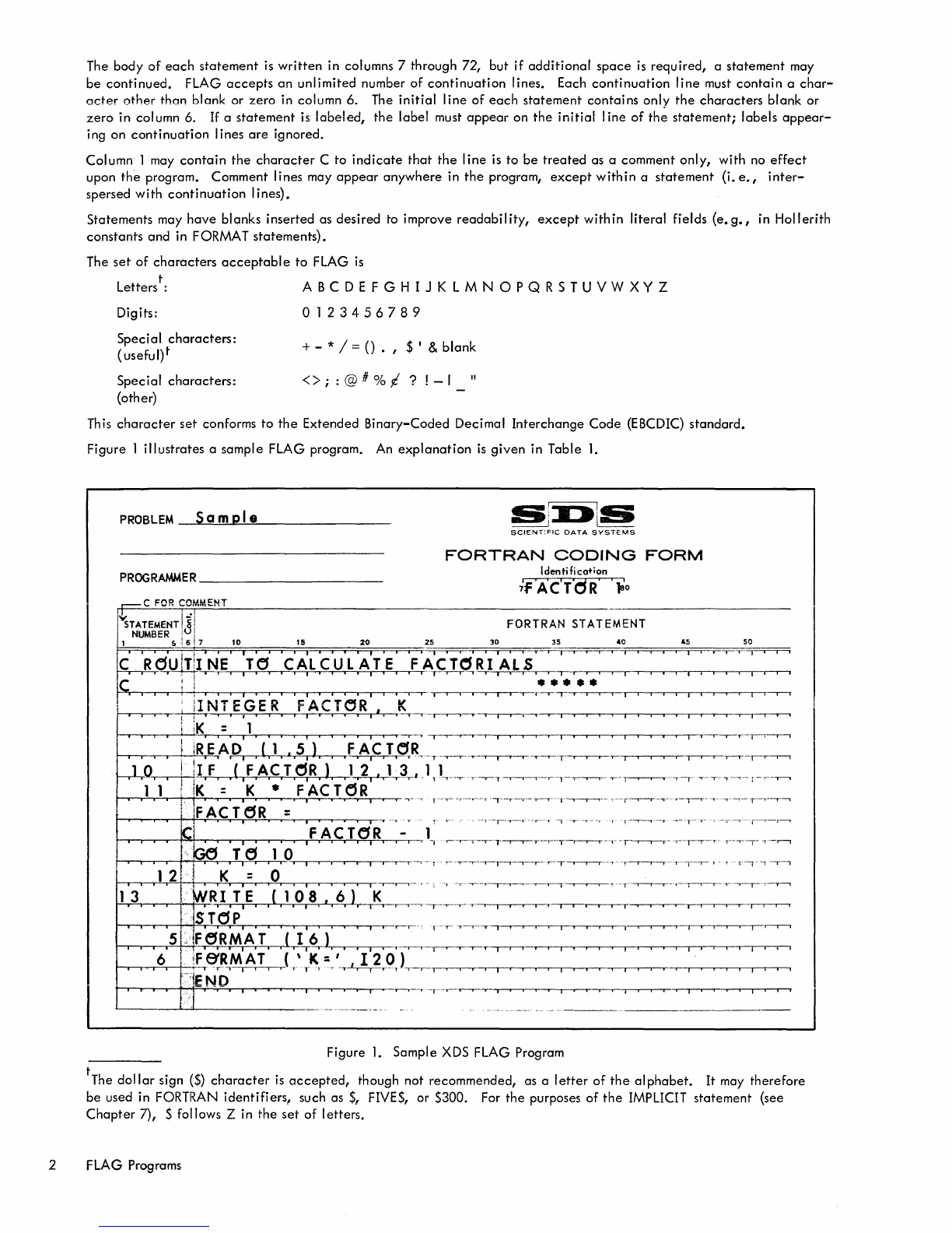
Figure
1
illustrates
a
sample
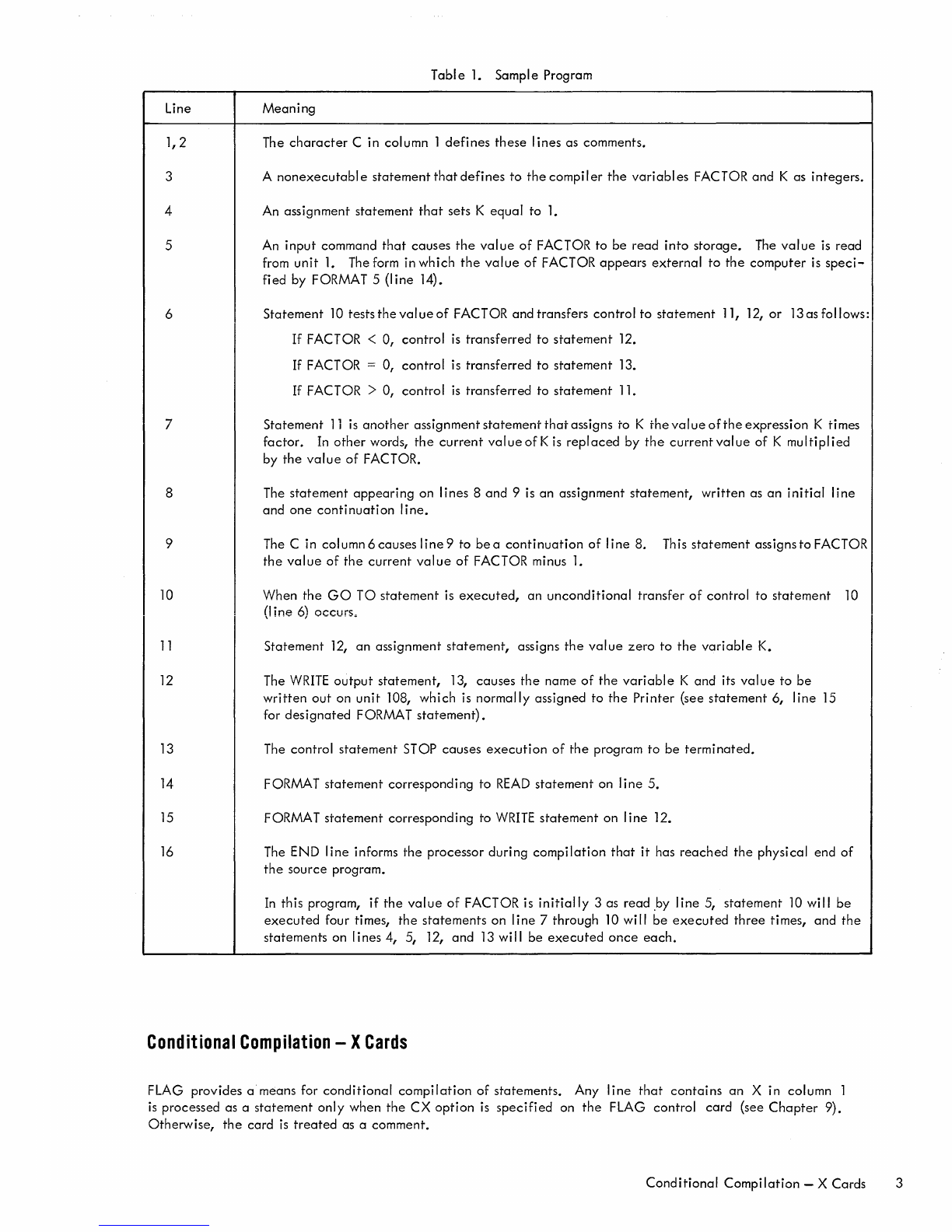
FLAG program. An
explanation
is
given
in Table
1.
PROBLEM
Sa
mpi e
S!:I:»ls
~
'---
SCIENT:FIC
DATA
SYSTEMS
FORTRAN
CODING
FORM
PROGRAMMER
____________________
_
Identification
FORTRAN STATEMENT
II
NT EGE R
FACTOR,
K
I-r--.-.,--r---t"""""+-"',
T I • , •
ii'
Ii'
• • , i
.·-,.--r··--~"T"-.,._r_r_l--y--r--rj-,--,--.,..--,r--r--.--.--...--.---.--,--
......
·
iK
=
iii
, • • • • !
~.
.,.
,'--'
,---r--r--r---r-...---r--.---r--r
..-,-,..---r-.
-,-,........,-,
-r,---.----.--r--.---.--..
--r""'-'--T-"-r-~
~-.--,.--r-+-!
.....,lR.;;E=;A,D,
,(
,1,
•
,5,
),
,
'f~-,.~TR-,-T-·,--y---r--,.__,__.-,---r---.--r-......,........-r--T"'"
",-,---'---r--~..---r-,--r-r-I
hI.O~J,F,
,(
,F,A,C,T,~R,)
,l-1r,J-r3.,J
.1,
lr-~T-r--T-r-.--,---rl---r-.,...--,.
y-1-.----.-.-
T-,"'·"-
~-;-'-""---'
1 1 I
lK
= K • FAC T
(j
R
lJFACT6R
= '
....
,
...
.,--
......
,
'·~·-T--~--
,---1'
12
13 WRI TE
(1
O'S
,
6)
'K~'-'
.
-'~·TT-'~-,.-
..
-T----r-r---.--'
-r·-r-r-.-·
...
I-..--
T ....
'-'-'---'-"--,---"
Iii
'
iii
i 1
iii
I i * ---,---"'"
·--TM-"...-----r--
"'l"'--,.
, i , i
T~.--.--r-r-r--T
•
Iii
¥
,.-.~
STC:SP
5 F
eRMA
T
(t'6)
t--.-·-,-.--r-=6~f-'-+1~_.~R,M:
~
T .
(::~
:",~-,_T"~
-.,
:-1""':
~-r_~-Q:
f:=:-~=~·~..,...-y-~,---,--.--r.
-r........-.,.--.,...-r.
~-r:---,---r-...,.....,r-T--r--,--,
'~';jEND
t--r-T-,-----r-+-+I,!=-r--"'-
-.=....-,-,
--.--.----r-.......-r,--r-,
.--.--.----.,
ir---r-",
~"-r""""-'"
"r
··Y·
....
,...........,.--....,.._·......--.-,
~,
.
..,--.--......--,-._
.
....,.......,.,
--.--.-.-
•
..,.....-rj
-.-...,..---,.-~
-..
------'
--_
....
_-----------
Figure
1.
Sample
XDS FLAG Program
tThe
dollar
sign
($)
character
is
accepted,
though
not
recommended,
as a
letter
of
the
alphabet.
It
may
therefore
be
used in FORTRAN
identifiers,
such as
$,
FIVES,
or
$300. For
the
purposes
of
the
IMPLICIT
statement
(see
Chapter
7), $ follows Z in
the
set
of
letters.
2 FLAG Programs