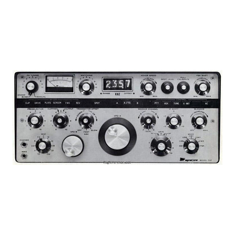
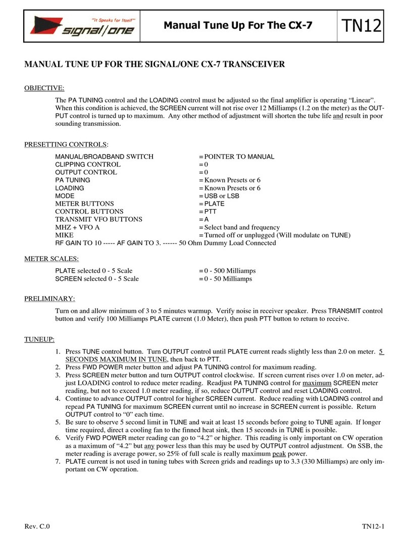
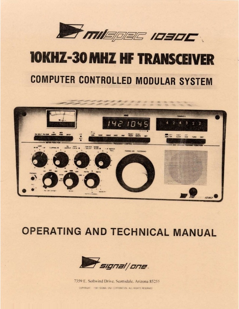
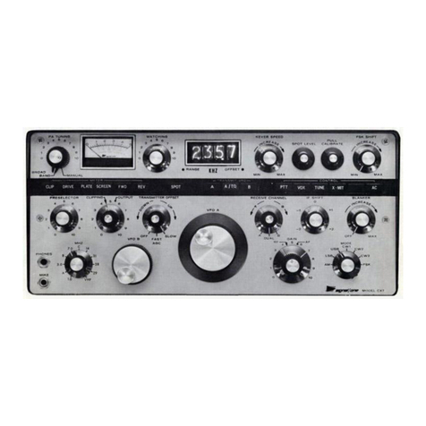
signal one CX-11 series A Quick start guide

BLACK CANYON INDUSTRIAL PARK * 8146 N. 23RD AVENUE
PHOENIX, ARIZONA 85021 * (602) 995-0608
W8CXS Revision
OPERATIONAL PROCEDURES
CX-11, SERIES A
HF SSB DELUXE INTEGRATED STATION
IMPORTANT
BEFORE APPLYING POWER IT IS ABSOLUTELY ESSENTIAL TO
READ AND OBSERVE CLOSELY ALL INSTALLATION AND OPERATING
INSTRUCTIONS IN THIS MANUAL.
THE CX-11, SERIES A DIFFERS IN IMPORTANT RESPECTS FROM
OTHER TRANSCEIVERS.
POSSIBLE SERIOUS DAMAGE TO THE EQUIPMENT WHICH MAY
RESULT FROM FAILURE TO COMPLY WITH ALL INSTALLATION AND
OPERATING INSTRUCTIONS HEREIN WILL NOT BE COVERED BY
WARRANTY.
SIGNAL ONE CORPORATION
BLACK CANYON INDUSTRIAL PARK
8146 N. 23RD AVE.
PHOENIX, ARIZONA 85021
PRINTED IN U.S.A.

BLACK CANYON INDUSTRIAL PARK * 8146 N. 23RD AVENUE
PHOENIX, ARIZONA 85021 * (602) 995-0608
2
W8CXS Revision
TABLE OF CONTENTS
FORWARD................................................................... 4
SECTION 1 - CX-11A DESCRIPTION............................................ 5
FEATURES AND SPECIFICATIONS ................................... 6
PHOTO - FRONT . ............................................... 7
PHOTO - REAR .. ............................................... 8
WARRANTY ...... ............................................... 9
SECTION 2 - OPERATIONAL PROCEDURES....................................... 10
WARNING ....... .............................................. 11
BASIC CONTROL SETUP .......................................... 12
EXPLANATION OF CONTROL FUNCTIONS ............................. 14
REAR PANEL CONNECTIONS ....................................... 22
SECTION 3 - FINAL TEST AND ALIGNMENT PROCEDURE........................... 25
SECTION 4 - CX-11A MODIFICATIONS......................................... 32
SECTION 5 - SCHEMATICS AND DRAWINGS...................................... 47
Upper Chassis Board Layout ................................... 48
Lower Chassis Board Layout ................................... 49
Al ...........PTO
A2, A32 ......RECEIVE LOW PASS FILTER; INCL. FILTER RESPONSE. .
A3 ...........POWER SUPPLY
A4 ...........BFO
A5 ...........DRIVER
A6 ...........AUDIO
A7 ...........MOTHER BOARD, FRONT PANEL
AS ...........IF
A9 ...........AGC
A10 ..........TRANSMIT MIXER
All ..........FINAL AMPLIFIER
A12 ..........TX PTO SWITCH
A13 ..........METER SWITCH
A14 ..........TRANSMIT MODE SWITCH
A15 ..........AUDIO FILTER
A16 ..........ALC
A17 ..........SYNTHESIZER
A18 ..........AC POWER BOARD
A19 ..........TX LOW PASS FILTER; INCL. FILTER RESPONSE.
A20 ..........RX HIGH PASS FILTER
A21 ..........POWER SUPPLY FILTER
A22 ..........RX MIXER ASSEMBLY (INCLUDES A23,A24,A25)
A26 ..........PTO MIXER

BLACK CANYON INDUSTRIAL PARK * 8146 N. 23RD AVENUE
PHOENIX, ARIZONA 85021 * (602) 995-0608
3
W8CXS Revision
A27 ..........TX FILTER SWITCH
A28 ..........COUNTER
A29,A30 ......LED. READOUT
A31 ..........S-METER
A33 ..........TX/RX RELAY
A34 ..........MODE SWITCH BOARD
A35 ..........MODE SWITCH WAFER
A36 ..........MOTHER BOARD, TOP
A37 ..........MOTHER BOARD, BOTTOM
FRONT PANEL INTERCONNECTION.....................................
A39 - Audio Filter Switch
A40 - Audio Selectivity Switch
A41 - Keyer; Sidetone; CAL: FSK
A42 - VOX; Clipping; TX Drive
A43 - AGC;RX Channel
A44 - IF;RX Shift; Blanker; Spot
REAR PANEL INTERCONNECTION......................................
A38 - Pass Transistor
A45 - RF Output; RX AUX Switch
A46 - Audio: Relay; ALC Jack
A47 - AC Power: Fuse
A48 - RF 1/0; Patch; Key Jack
BLOCK DIAGRAM ..................................................
Signal Routing - Coaxial Cable..................................

BLACK CANYON INDUSTRIAL PARK * 8146 N. 23RD AVENUE
PHOENIX, ARIZONA 85021 * (602) 995-0608
4
W8CXS Revision
Forward
There were 111 Sign al/ On e CX-11A’s prod uced . At one tim e Paul Koll ar 8CXS kept a lis t of wh o
owned each one. And he had probably repaired each of them.
Paul was an incredible man. He only repaired Signal/One radios, and did it extremely well. He was
meticulous in his work and made notes about what was wrong with the radios, and how to fix them. He
knew the history of the company and the radios, and could go on for hours telling the history of Signal/
One. He was the acknowledged master of Signal/One repair.
This is an update of the original manual that includes all of Paul’s notes, drawings, and corrections to
the schematics. Additional material on modifications has been included, as has a number of photo-
graphs.
I hope you find the information contained herein useful and informative.
Bill Turini KA4GAV
HAManuals
February, 2000

BLACK CANYON INDUSTRIAL PARK * 8146 N. 23RD AVENUE
PHOENIX, ARIZONA 85021 * (602) 995-0608
5
W8CXS Revision
Section 1
CX-11A Description

BLACK CANYON INDUSTRIAL PARK * 8146 N. 23RD AVENUE
PHOENIX, ARIZONA 85021 * (602) 995-0608
6
W8CXS Revision
Features and Specifications
FEATURES:
1. DUAL VFO’s, INDEPENDENT C O NTROL: Capable of simul aneously receiv-
ing wo sepa ra e frequencies wi hin he same band and rasm i ing on
ei her.
2. 150 WATT OUTPUT from a solid s a e, no une final u ilizing only 50% of
i s 300 Wa ou pu capa b ili y hrough he use of Mo orola
®
RF Power and
Hybrid Linear Am plifier Modules.
3.
SYNTHESIZED HF 160-10M BAND COVERA GE: Addi ional 1 MHz bands
may be added by programming he diode ma rix.
4. UNEQUALED SELECTIVITY from 3 cascaded crys al fil ers, IF shif plus
ac ive audio band pass fil ers and a uneable peak no ch fil er. All add up
o he mos powerful an i-QRM sys e m available oday.
5. ACTIVE DOUBLE BALANCED SILICONIX
®
MIXERS provide a plus 20 dbm,
3rd. order in ercep poin (bes a ainable receiver IMD in an ama eur
band ransceiver.
6. RF SPEECH PROCESSOR. RF envelope clipper plus cascaded 8 pole crys al
fil ers in SSB
7 . LED FREQUENCY READO UT: Six digi , 100 Hz resolu ion display. .43”
charac er he igh ; brigh ness and mul iple colors insure accura e wide
angle in erpre a ion.
8. CW KE YER; INDEPENDENT AG C; QSK-FASTBREAK IN CW; VOX; RIT;
NOISE BLANKER; FULL METERING ..... ALL STANDARD WITH SIGNAL/
ONE
9. POWER SUPPLY (BUILT-IN): Heavy du y HyperSil
®
ape wound rans-
former for excep ional regula ion and power wi h compac size and
weigh .
10. MODULAR CONSTRUCTION u ilizing a mass ermina ion ribbon in ercon-
nec ion 3M
®
sys em for easy circui board accesssabili y.
SIGNAL/ONE MODEL CX-11A SPECIFICATIONS
GENERAL:
1.
Frequency Coverage:
All ama eur bands 1.8 o 30 MHz in full 1 MHz
ranges. An addi ional 1 MHz band may be added in a ny of he four
ranges; 2.0; 4.0:7.0; 8 .0:14.0; and 15.0:21.0 MHz by programming he
diode ma rix for he LSI Digi al PLL Syn hesi zer.
2.
Frequency Control:
T wo iden ical, precision VFO’ s 1 MHz uning range,
50 KHz overlap wi h nominal 25 KHz per knob res olu ion.
3.
Readout:
Accuracy lineari y and rese abili y o 100 HZ a any poin in
any band af er calibra ion agains WWV a 15 MHz. MSI Digi al Fr equency
Coun er, six digi .43” charac er heigh , high brigh ness and mul iple red,
amber and green LED ’s insure accura e wide angle in erpre a ion. Read-
ou upda es 20 imes per second.
4.
Spotting:
Push bu on provides audio bea no e for spo ing wh en using
separa e VFO’s or T ransmi Offse /T ransceive Mode.
5.
T/R Switc hing:
Push- o- alk or fas -a ack VOX; QSK, full break-in CW;
fas key-up receiver recovery independen of AGC decay. Isola ed ermi-
nals for con rol of ex ernal am plifier.
6.
CW Keyer:
Buil -in elec ronic keyer wi h independen speed and weigh
con rol, 5 o 60 wpm. Separa e jacks for keyer paddle and manual key.
7.
Frequency Control Modes:
Transceive wi h ei her VFO, “spli ” using
bo h VFO’s, ransceive on ei her VFO plus independen receive-only on he
o h er, or “Transmi and Receive Offse ” ransceive (Transmi and receive
frequencies rack and may be ins an ly offse up o plus or minus 3 KHz
from receive frequency).
8.
E ission Modes:
SSB, CW, FS K
9.
Power Supply:
Buil -in heavy du y supply for 115/230 vol s, 50 o 400
Hz. Hypersil
®
Transformer for excep ional regula ion and power wi h very
small size and weigh . Co mple ely self pro ec ing - bo h hermal and cur-
ren overload. Requires approxima ely 100 wa s receive, 600 wa s peak
a full inpu .
10.
Construction:
All cri ical circui ry (excep large power supply compo-
nen s) is modular on glass epoxy e ched circui boards u ili zing gold pla ed
socke s and pins for ea sy removal of all ransis ors, in egra ed circui s and
circui boards co nnec ed by a mass ermina i on ribbon cable sys em.
11.
Size and Weight:
16
¼
”W, x 7
¼
”H, x 14” deep overall, less fee. 40
pounds.
RECEIVING SYSTEM:
1.
Active Mixers.
Two Quad J FET Silion ix
®
mixers.
2.
Sensitivity.
Be er han -116 dBm (.25
µ
v) for 10 dB S/N ra io a 10
me ers (2.4 KHz ban dwid h). Ma ched 50 ohm measuremen (10 dB noise
figure).
3.
Selectivity.
S andard SSB - dual ma ched 2.4 kHz 8 pole crys al band-
pass fil ers deliver 16 p ole 1.4:1 sh ape fac or perform ance (6dB /60dB).
4.
Dyna ic Range.
98 dB wi h a 2.4 KHz bandwid h.
5.
Third Order Intercept Point.
Plus 20 dBm based on wo -23 dBm sig-
nals a he an enna connec or, separa ed by 25 kHz, crea ing in ermodula-
ion dis or ion produc s no less han 90 dB below ei her of he in erfacing
signals.
6.
Cross Modulation.
W i h a desired signal grea er han -52 dBm, in a 2.4
kHz bandwid h, an unwan ed si gnal, 30% modul a ed, removed no less
han 25 kHz m us be grea er han pus 2 dBm o produce an ou pu 30 dB
below he ou pu produced by he desired signal.
7.
Co pression.
(Blocking) wi h a desired signal of -52 dBm an unwan ed
signal more han 25 kHz removed mus be grea er han plus 7 dBm o
reduce he ou pu by 3 dB.
8.
Synthesizer Phase Noise.
in 1 Hz ban dwid h, -80 db below carrier.
9.
Post Detection Peak/N otch Filter
wih adjusable frequency noch
dep h and 2.4, 1.5, 1.0, 0.4, 0.1 kHz band wid h selec ivi ies.
10.
Audio Output.
2 wa s.
11.
IF Shift.
Second IF adjus able up o plus or minus 2 kHz wi h respe c o
IF fil er passband for in erference rejec ion and receiver audio passbband
selec ion. T racking error, zero.
12.
Dual Receive.
Two cha nnels usable separa ely or simul aneously, con-
inuously variable rela ive RF gain c on rol. Ei h er channel may be used for
ransceiving and he o her for r eceive-only.
13.
Noise Blanker.
Pre-IF blanker wi h adjus able hreshold.
TRANSMITTING SYSTEM:
1.
Power A plifier.
Soli d s a e, comple el y broad-band driver and final;
wo rugge d, M o orola
®
RF power ransis ors MRF 422, linear power
amplifier conduc ion-coupled o massive ex ruded hea sink. 150 wa s
dissipa ion ra ing a 25 C ambien . Comple e hermal pro ec ion. Pre-
uned bandpass ou pu fil er requires no adjus men . Nominal 50 ohm
ou pu impedan ce will opera e in o any VSWR w i hou dam ager. Driver
and final broadband 1.8 o 30 MHz.
2.
Power Output.
150 wa s CW/PEP ou pu all bands and modes. Ou pu
con inously adjus able down o less han 1 wa .
3.
Inter odulati on Distor tion.
35 dB below each of wo ones a full PEP
ou pu , ypical.
4.
Har onic and Spurious Output.
-65 dB min. Mee s FCC par 97.73
(-40dB plus 10Log of mean power ou pu ).
5.
Carrier and Undesired Sideband Supression.
60 dB minimum.
6.
Speech Processing.
RF envelope clipping plus cascaded 8 pole crys al
fil e rs in SSB. Clipping adjus able 0 o 20 dB nominal.
7.
Metering.
PA curren , PA vol age, clipping, drive, forward and reflec ed
power.
NOTE:
All Signal One Produc s significan ly exceed FCC speci fica ions limi ing spurious
emissions.
Price and specifica ions subjec o change wi hou no ice or obliga ion.

BLACK CANYON INDUSTRIAL PARK * 8146 N. 23RD AVENUE
PHOENIX, ARIZONA 85021 * (602) 995-0608
7
W8CXS Revision
PHOTO - FRONT

BLACK CANYON INDUSTRIAL PARK * 8146 N. 23RD AVENUE
PHOENIX, ARIZONA 85021 * (602) 995-0608
8
W8CXS Revision
PHOTO - REAR

BLACK CANYON INDUSTRIAL PARK * 8146 N. 23RD AVENUE
PHOENIX, ARIZONA 85021 * (602) 995-0608
9
W8CXS Revision
LIMITED WARRANTY
Signal/One agrees to repair or replace without charge any equipment parts or
accessories which are defective as to workmanship or materials to the origi-
nal purchaser for a period of 1 year from the date of purchase. Provided
that:
1. The purchaser returns the defective unit to Signal/One factory
service department, transportation prepaid when directed to do
so.
2. Notice of failure is provided Signal/One factory service depart-
ment, in writing within one year of date of purchase.
3. The equipment was purchased from a factory authorized distribu-
tor and the warranty card validated at the time of purchase.
Warranty void when passed to a third party.
This warranty is void if equipment is altered, modified or repaired by other
than authorized Signal/One factory service department.
Signal/One reserves the right to make any changes in design or to make addi-
tions to, or improvements in, Signal/One products without imposing any obli-
gations upon Signal/One to install them in previously manufactured Signal/One
products.
No other warranties expressed or implied shall be applicable to
Signal/One equipments and the foregoing constitutes the sole liability of the
company with respect to its manufactured products.
WARRANTY REPAIRS OUT OF WARRANTY REPAIRS
Equipment to be returned under the If equipment is to be repaired
guarantee should be preceded by or modified after expiration of
notification giving full particulars warranty, correspondence should
of the defect. Signal/One factory be directed as above. Signal/One
service department will provide instruc-will provide service instructions
tions with respect to returning unit direct from the factory. Correspon-
for service. dence should be directed to:
SIGNAL/ONE CORPORATION
Serial No. Black Canyon Industrial Park
Phoenix, Arizona 85021
UNDER THE REGULATIONSOF THE MAGNUSON-MOSS WARRANTY ACT, THE SIGNAL/ONE WAR-
RANTY POLICY IS CLASSIFIED AS A LIMITED WARRANTY.
ALL SIGNAL ONE PRODUCTS MANUFACTURED IN THE UNITED STATES of AMERICA

BLACK CANYON INDUSTRIAL PARK * 8146 N. 23RD AVENUE
PHOENIX, ARIZONA 85021 * (602) 995-0608
10
W8CXS Revision
Section 2
Operational Procedures

BLACK CANYON INDUSTRIAL PARK * 8146 N. 23RD AVENUE
PHOENIX, ARIZONA 85021 * (602) 995-0608
11
W8CXS Revision
WARNING
LINEAR AMPLIFIER OPERATION The CX-11A external mercury reed relay
has a contact rating of 25 VA max., 100 VDC max., 1 AMP max.
switching current, and 2 AMP max. carry current rating. Linear
Amplifier unprotected T/R relay coils can produce an inductive
voltage kick as high as several thousand volts on relay opening.*
The majority of Amateur Linear Amplifiers are not designed for
high speed T/R switching transceivers that feature full QSK break
in, i.e. Vacuum Reed Relays required both in the transceiver and
linear. The Alpha 77D and 77S are the only linears currently man-
ufactured that can utilize the full QSK capability of the CX-11A.
ADDITIONAL OPERATING INFORMATION The clipping internal adjustment
has been set and with the clipping pot at 0, whistling into the
microphone with the meter function in the clipping position the
meter should not exceed S-1 with the output control at 10 giving
full power output.
EXTERNAL KEYER OPERATION To key the CX-11A, an external keyer must
supply a ground to the Key Jack; open circuit voltage is -3.5 VDC,
0 VDC keyed in transmit.
*Exceeding the contact rating will void the warranty for the
CX-11A external reed relay.

BLACK CANYON INDUSTRIAL PARK * 8146 N. 23RD AVENUE
PHOENIX, ARIZONA 85021 * (602) 995-0608
12
W8CXS Revision
BASIC CONTROL SETUP
Control Setting
AC Off (Button Out)
Audio Filter Off
Selectivity 2.4
Keyer Any Position
Sidetone Level Mid-Range
Calibrate In
FSK Shift CCW
Mode USB or LSB
Clipping 3
TX Drive 0
AGC Slow
TX Offset Mid-Range
Meter FWD PWR
TX VFO A
Control PTT
RX Channel A, Center Knob Any Position
RX Shift 0, Both Knobs
Noise Blanker Off
MHZ 1,3,7,14,21,28 or 29
RF Gain 10
Audio Gain 3
Anti Vox 0
Vox Cain 3
Vox Delay 2
ANT Slide Switch (Rear Panel) Comm
Connector Assembly Procedure
Mic Jack Assembly PJ-068
Solder Mic cable to Jack as follows:
1. Tip of jack - PTT circuit
2. Ring of jack- Mic audio
3. Sleeve of jack - Common ground

BLACK CANYON INDUSTRIAL PARK * 8146 N. 23RD AVENUE
PHOENIX, ARIZONA 85021 * (602) 995-0608
13
W8CXS Revision
Check for the following conditions before energizing the radio:
1. Antenna connected to rear panel jack.
2. Fuses installed per rear panel markings.
3. Dummy plug installed in accessory jack (radio will not operate without
plug). Note - red dots must match; reversing plug will cause damage.
4. A.C. Power Cord connected.
5. Loudspeaker connected to rear panel “spkr”. Jack or earphones
plugged into front panel “audio” jack.
The CX-11A may now be energized by depressing the AC pushbutton - you will
now be able to receive some signals by tuning VFO A.
To Transmit, depress the tune button and advance the TX drive
control until the amber warning light on the meter face just
begins to turn on, or until the forward power meter indication
ceases to increase. The amber light marks the point of excessive
drive. A red warning light is also included on the meter face, it
shows that the high current power supply is out of regulation when
lit -- under no circumstances should the drive control be advanced
to the point at which this red light turns on. The out-of-regulation
condition is usually caused when trying to operate with inadequate
station wiring and/or excessively low line voltage.
Depress the “PTT” or “VOX” pushbutton to cancel the “tune” button;
the CX11A is now ready for normal full-power transmission on either
Single Sideband or CW. It is not advisable to remain in “tune” for
more than one minute; long periods of this type of transmission
could allow the amplifier or power supply to activate the automatic
high temperature cut-off circuitry. When this happens, the transmit-
ter will become inoperative until the heat sinks have been allowed
to cool sufficiently. (The red meter light will indicate during
thermal cut-off; also, the meter will indicate zero with the “P.A.
Volt” button depressed).

BLACK CANYON INDUSTRIAL PARK * 8146 N. 23RD AVENUE
PHOENIX, ARIZONA 85021 * (602) 995-0608
14
W8CXS Revision
Explanation Of Control Functions
Note: All controls only associated with the receive function are marked
with green lettering; transmit with red. Any controls which affect
both receive and transmit are marked with yellow lettering.
1. AC On/Off -- self explanatory
2. Mode Every CX-11A will operate in the AM, LSB, USB, and CW 1 posi-
tions; the CW2 FSKI/CW3 & FSK 2 positions represent modes requiring
the installation of optional crystal filters.
3. Control Pushbuttons
a PTT; Push-To-Talk:pressing the button sets up the condition in
which the transmitter can only be actuated by an external switch,
such as a microphone pushbutton, footswitch -- while in AM, LSB,
USB, or FSK modes. In the CW mode, the transmitter is automati-
cally actuated by keying either a standard hand key or auto key
paddle.
bVOX; voice actuation: Transmitter will be automatically actuated
upon speaking into microphone.
cTUNE: Actually a misnomer -- creates a “key down” CW transmit con-
dition regardless of mode switch position; useful in setting or
measuring RF output power.
dTRANSMIT: Depressing this button forces a transmit condition. To
return to receive simply depress PTT or VOX. In the CW mode, the
effect is to provide standard non-break-in operation.
4. MHZ Used to select the desired one-megahertz-wide range of operation.
Separate low-pass and high-pass filters are selected for six ranges
covering 1.8 - 30 MHz. The selectivity of the receive band pass fil-
ters further enhance the receive circuitry's excellent linearity in
the presence of strong out of band signals.
6. VFO A Precision permeability tuned oscillator provides I MHZ + tuning
range for both transmit and receive; approx 25 KHZ/knob revolution.
7. VFO B Identical to VFO A. Dual VFO's provide simultaneous reception
of two different frequencies, if desired.
8. Receive Channel Selector
a) Large outer knob selects which VFO determines the receive
frequency; A, B, or both A & B.
b) Small knob is a balance control which can be used to modify the
relative signal levels of two different stations being received in
the A+B receive mode.

BLACK CANYON INDUSTRIAL PARK * 8146 N. 23RD AVENUE
PHOENIX, ARIZONA 85021 * (602) 995-0608
15
W8CXS Revision
9. RX Shift
a) The larger outer knob provides the operator with a means of moving
the IF passband up or down relative to the “Zero-Beat” frequency.
(Used for placing selectivity skirt at optimum point for rejecting
interfering signals).
b) The small center knob is used to offset the frequency of VFO A
during receive. This feature is activated by pulling out on the
knob and rotating it while watching the results on the readout.
The offset is automatically cancelled during transmit.
10. Noise Blanker
Very effective in reducing pulse noise. The control should only b
advanced far enough to reduce noise to an acceptable level. Be sure
to return the knob to the full off position when the noise blanker is
not required; otherwise, strong signals within 15 KHZ may appear to
cause receiver distortion.
11. RF Gain (Outer Knob)
Normally left in the full clockwise position; this control may be
rotated counter clockwise to manually override the automatic Gain
Control circuitry. Many operators reduce the RF Gain to eliminate
annoying background interference while receiving relatively strong
stations.
12. AF Gain (Inner Knob)
Use this knob to control the audio output level of the receiver.
Notice that the control has no effect on the CW Sidetone or Spot Tone
levels (for which separate controls are provided).
13. Calibrate
Caution: Allow 5 min. warm-up before making adjustments. Switching
the knob clockwise causes a signal to appear every 100 KHz. Using the
appropriate VFO, set the readout to indicate any exact multiple of
100 KHz (last three digit, are zero). Then insert a thin blade screw-
driver into the calibrate knob; adjust to obtain zero beat.... this
is best heard by manipulating the IF shift control to obtain good
audio response near zero beat. The calibration procedure need only be
performed once at WWV 15.0 MHz to insure accurate frequency readouts
on any selected band.
14. Audio Filter
The CX-I1A is equipped with a versatile peak/notch/filter. When
switched to the “notch” position, a narrow segment of the receiver’s
audio response is greatly attenuated. Switching to “peak” provides a
condition which is exactly opposite to that provided in “notch”; that
is, all but a narrow bandwidth is greatly attenuated. The center fre-

BLACK CANYON INDUSTRIAL PARK * 8146 N. 23RD AVENUE
PHOENIX, ARIZONA 85021 * (602) 995-0608
16
W8CXS Revision
quency about which a “notch or peak” is located is governed by the
position of the “center frequency” knob.
15. Audio Selectivity
Normally, this switch should remain in the 2.4 KHZ position. Narrower
bandwidths down to only 100 HZ are provided to optimize the reception
of weak signals in the presence of noise and/or strong interfering
signals.
16. AGC
Receiver Automatic Gain Control; normally left in the “slow” posi-
tion. The RF Gain Control must be used to manually set the Receiver
Gain if this control is turned to “off”.
17. TX VFO
These pushbuttons specify what controls will be used to determine
the transmit frequency:
A; transmit frequency set by VFO A.
A.T.O.; transmit frequency set by VFO A and by the position of the
“A TX Offset” control. A green dot will appear in the readout to
remind the operator that this offset mode has been selected.
B; transmit frequency set by VFO B.
18. VFO Spot
Serves two purposes:
1) Allows an audible beat tone to be produced -- used to synchronize
the two VFO's to a higher resolution than provided by the readout.
(See “Spot Level” Control description).
2) When depressed, the frequency shown on the readout is exactly
equal to the transmit frequency -- useful in avoiding having to
transmit in order to check transmission frequency.
19. Spot Level
The loudness of the VFO spot tone is independent of the AF gain con-
trol. Set the spot level control for the desired loudness.
20. VOX Gain
Used to set the minimum level at which the operators voice will actu-
ate the VOX circuit.
21. AntiTrip
Clockwise rotation of this control increases the VOX circuits immu-
nity to being actuated by receiver audio output.
22. Delay
Controls the amount of time that the VOX circuit remains actuated
after the operator has stopped talking into the microphone.

BLACK CANYON INDUSTRIAL PARK * 8146 N. 23RD AVENUE
PHOENIX, ARIZONA 85021 * (602) 995-0608
17
W8CXS Revision
23. Meter Pushbuttons
Meter reads received signal strength during receive except when
“P.A. VOLT” or “P.A. CUR.” buttons are depressed.
a) P.A. VOLT: Press to monitor the power amplifier voltage. Note that
signal strength indications cannot be observed with this function
selected. Approximately 50 volts*full scale.
b) P. A. Cur.: Press to monitor power amplifier current consumption.
Approximately 50 amps*full scale. Note that signal strength indi-
cations cannot be observed whenever this button is depressed.
c) CLIPPING: When this button is depressed, the meter will give a
relative indication of the amount of RF clipping present during
voice transmissions.
d) DRIVE: When this button is depressed, the meter will indicate the
activity of the ALC (Automatic Level Control) circuitry during
transmit. The meter reading should never be allowed to rise above
20% deflection. A condition of excessive drive will usually result
in distorted transmissions. The yellow warning light on the left
side of the meter face is also an indicator of excessive drive,
but responds much faster than the meter movement.
e) FWR PWR: When this button is depressed, the meter shows a relative
indication of forward power during transmit. An 80% meter deflec-
tion corresponds to 150 watts output (see manual for calibration
data). (see page 14, Table 1)
f) REV PWR: When this button is depressed, the meter shows a relative
indication of reverse power. (See 6B, Table 1)
24. TX Drive (Center Knob)
Controls the power output of the transmitter; always follow these
rules when adjusting this control:
1) Do not advance TX drive any further than the point at which the
power output ceases to increase.
2) Do not advance TX drive beyond the point at which the yellow warn-
ing light just begins to indicate and/or the drive meter shows a
higher than 20% deflection.
3) Reduce drive if the red warning light shows the slightest indica-
tion (power supply overload condition).
25. Clipping
RF speech clipping may be used to increase the average output power
without increasing peak output power during voice transmissions. This
feature is extremely effective in extending ones readability under
marginal conditions. Use only as much clipping as necessary - as with
any clipping process, audio distortion is an unavoidable by-product.
The knob is usually left at 2 or 3 during normal operating condi-
tions.
*With modified meter multiplier values.

BLACK CANYON INDUSTRIAL PARK * 8146 N. 23RD AVENUE
PHOENIX, ARIZONA 85021 * (602) 995-0608
18
W8CXS Revision
26. A TX Offset
Allows the operator to offset the transmit frequency as much as 3 KHZ
with respect to the receive frequency when using VFO A for

BLACK CANYON INDUSTRIAL PARK * 8146 N. 23RD AVENUE
PHOENIX, ARIZONA 85021 * (602) 995-0608
19
W8CXS Revision
Addendum to Item # 26 A TX Offset:
A/T.O. CW Transceive Operation
1. Depress A/T.O.
2. Depress Spot Button and set A/T.O. offset control 800 Hz high in
relation to receiver frequency displayed on digital counter. (Approx.
7 o'clock on A/T.O. knob).
3. When set, no additional adjustments are necessary for any frequency
tuned by PTO A unless a shift of the transmit CW frequency is desired,
for example, during a DX pile up a slight shift of 100 Hz up or down.
A PTO Transceive Operation
1. Pull RX Shift knob and depress Spot button. Set for 800 Hz low in
relation to the receive frequency. displayed on digital counter.
(Approx. 11 o'clock on A/T.O. knob).

BLACK CANYON INDUSTRIAL PARK * 8146 N. 23RD AVENUE
PHOENIX, ARIZONA 85021 * (602) 995-0608
20
W8CXS Revision
DETERMINING ACTUAL FORWARD AND REFLECTED POWER
Table 1:
METER INDICATION EQUIVALENT WATTS
0.0 0
0.2 1
0.4 2
0.6 4
0.8 7
1.0 10
1.2 14
1.4 19
1.6 25
1.8 33
2.0 40
2.2 48
2.4 57
2.6 66
2.8 75
3.0 85
3.2 100
3.4 108
3.6 118
3.8 130
4.0 140
4.2 150
4.4 170
4.6 190
4.8 200
5.0 210
This manual suits for next models
1
Table of contents
Other signal one Transceiver manuals
Popular Transceiver manuals by other brands
Kenwood
Kenwood TK-2202 Service manual

Albrecht
Albrecht AE 540 Servise manual
Kenwood
Kenwood ProTalk TK-3401D instruction manual
Kenwood
Kenwood ProTalk TK-3401D Quick reference guide
NXP Semiconductors
NXP Semiconductors freescale semiconductor MC13211 Reference manual
Nokia
Nokia NSM-5 SERIES Disassembly & troubleshooting instructions
