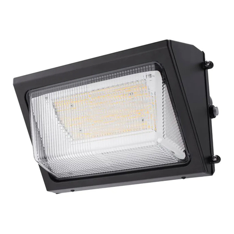
SIGNIFY RoadFocus PLUS Security User manual
Other SIGNIFY Outdoor Light manuals
SIGNIFY
SIGNIFY Stonco Keene DualSelect WP60-SCT-G2-10-BZ User manual
SIGNIFY
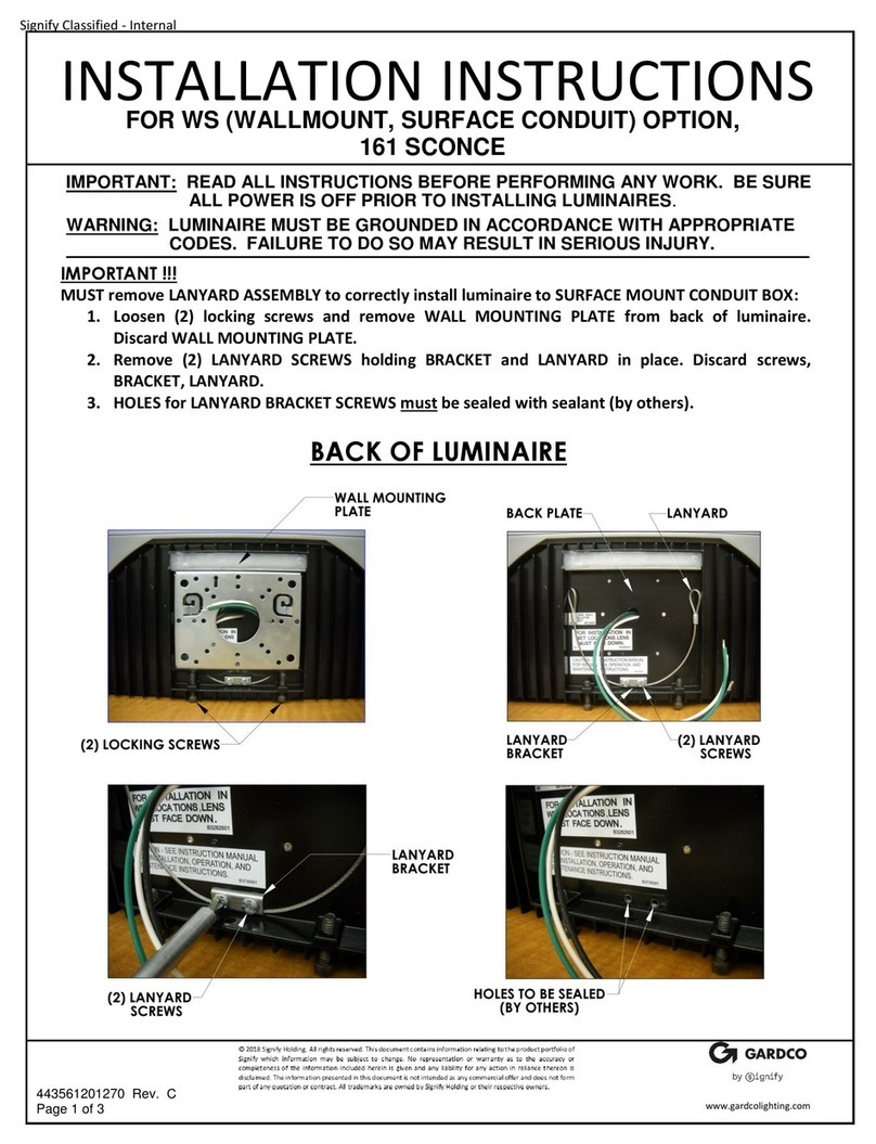
SIGNIFY GARDCO 161 SCONCE User manual

SIGNIFY
SIGNIFY GARDCO OptiForm OPF-S User manual
SIGNIFY
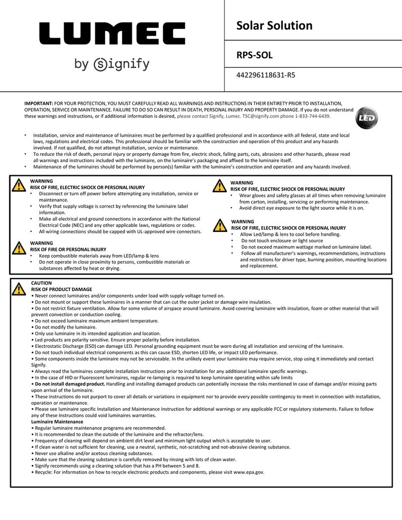
SIGNIFY LUMEC RPS-SOL User manual
SIGNIFY
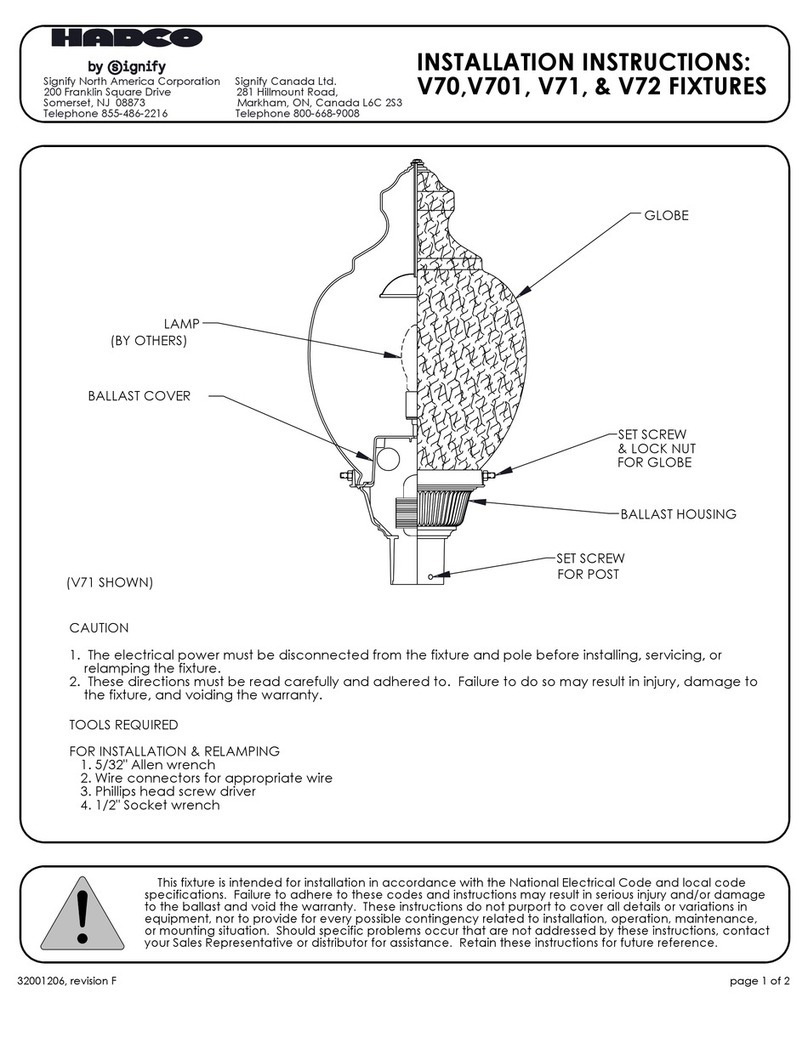
SIGNIFY HADCO V70 User manual
SIGNIFY
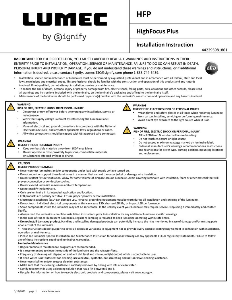
SIGNIFY LUMEC HighFocus Plus User manual

SIGNIFY
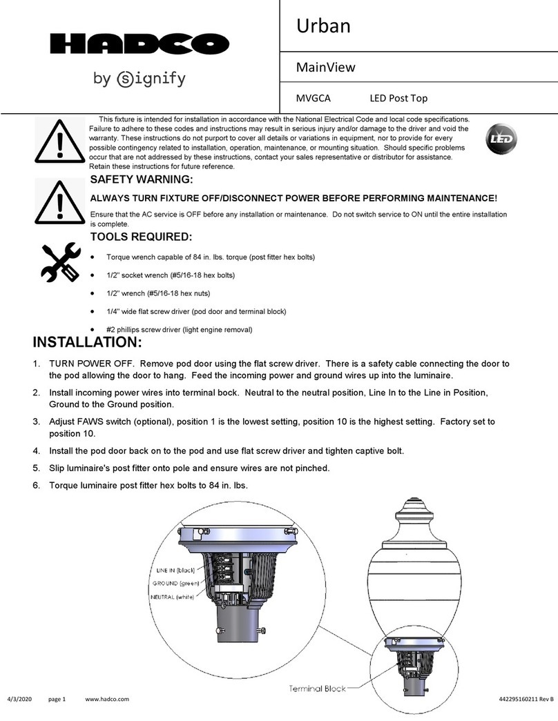
SIGNIFY Gardco Pureform Gen. 2 Pedestrian Post Top User manual
SIGNIFY
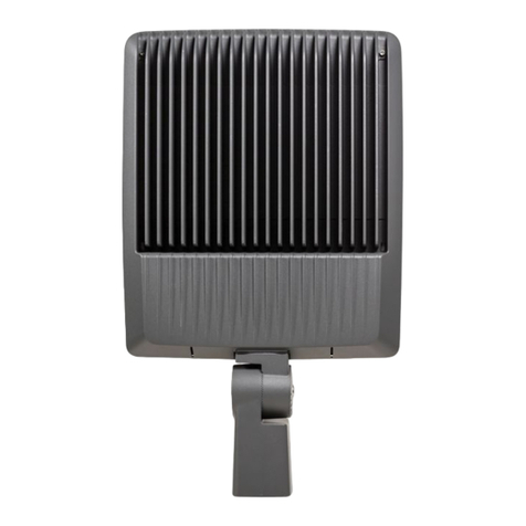
SIGNIFY Hadco MainView MVGCA Series User manual
SIGNIFY
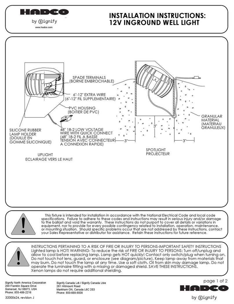
SIGNIFY Gardco CSFS User manual
SIGNIFY
SIGNIFY HADCO iL336 User manual

SIGNIFY
SIGNIFY Gardco PowerForm Area/Site User manual
SIGNIFY
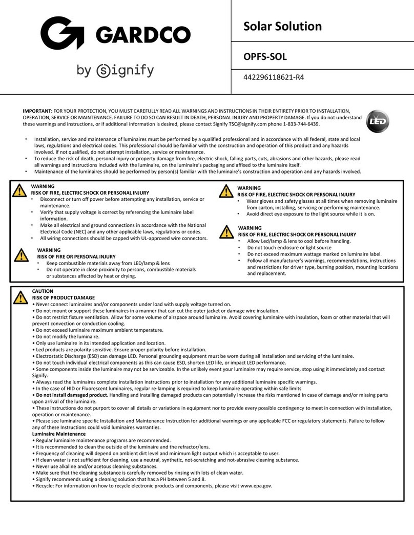
SIGNIFY GARDCO OptiForm Solar User manual

SIGNIFY
SIGNIFY LIGHTOLIER LyteSpan BoldFlood LWWJ Series User manual
SIGNIFY
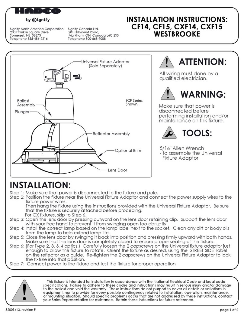
SIGNIFY Hadco Westbrooke CF14 User manual
SIGNIFY
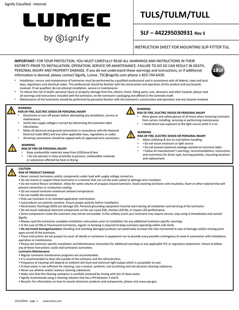
SIGNIFY Lumec TULS User manual
SIGNIFY
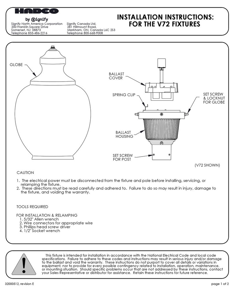
SIGNIFY HADCO V72 User manual
SIGNIFY
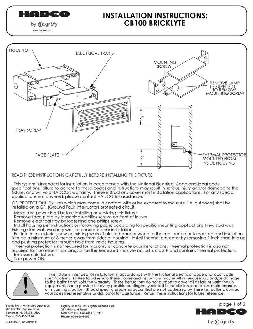
SIGNIFY HADCO CB100 User manual
SIGNIFY
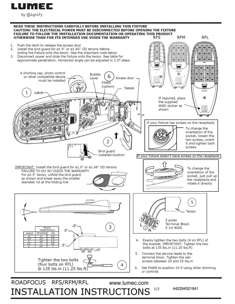
SIGNIFY LUMEC ROADFOCUS RFS User manual
SIGNIFY
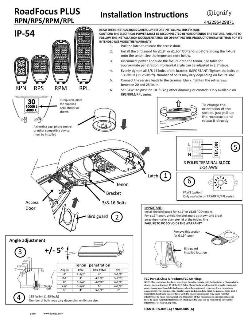
SIGNIFY RoadFocus PLUS User manual
Popular Outdoor Light manuals by other brands

Kichler Lighting
Kichler Lighting HELEN 37536 instructions

Thorn
Thorn OXANE L installation instructions

esotec
esotec Solar Globe Light multicolor 20 operating instructions

mitzi
mitzi HL200201 ELLIS Assembly and mounting instructions

HEPER
HEPER TILA S AFX 3 Module Installation & maintenance instructions

Designplan
Designplan TRON 180 installation instructions

BEGA
BEGA 84 253 Installation and technical information

HEPER
HEPER LW8034.003-US Installation & maintenance instructions

HEPER
HEPER MINIMO Installation & maintenance instructions

LIGMAN
LIGMAN BAMBOO 3 installation manual

Maretti
Maretti TUBE CUBE WALL 14.4998.04 quick start guide

Maxim Lighting
Maxim Lighting Carriage House VX 40428WGOB installation instructions


