SIGRIST VisGuard 2 User manual

Document number: 14162E
Version: 2
Valid from: S/N 704010/
SW V529
INSTRUCTION MANUAL
VisGuard 2
Visibility Monitor / Dust Monitor

Copyright© SIGRIST-PHOTOMETER AG, subject to technical changes without notice 4/2018
SIGRIST-PHOTOMETER AG
Hofurlistrasse 1
CH-6373 Ennetbürgen
Switzerland
Tel. +41 41 624 54 54
Fax +41 41 624 54 55
inf o@photometer.com
w w w .photometer.com

Contents Instruction Manual VisGuard 2
14162E/2 3
Contents
1General user information........................................................................................7
1.1 Terms used in this document (glossary) ........................................................7
1.2 Purpose of the Instruction Manual ...............................................................7
1.3 Target group of the documentation .............................................................7
1.4 Additional documentation ..........................................................................7
1.5 Copyright provisions ..................................................................................7
1.6 Document storage location .........................................................................7
1.7 Order document ........................................................................................8
1.8 Proper use ................................................................................................8
1.9 Use restrictions ..........................................................................................8
1.10 User requirements .....................................................................................8
1.11 Declaration of conformity ...........................................................................8
1.12 Dangers when not used properly .................................................................9
1.13 Meaning of the safety symbols....................................................................9
1.14 Meaning of the pictograms.......................................................................10
2Instrument overview ............................................................................................11
2.1 Overview of a measuring point with SIPORT 2.............................................11
2.2 Overview of a measuring point with SICON only .........................................11
2.3 Overview of a multiple measuring point with SICON M................................12
2.4 Designation of the components.................................................................13
2.4.1 Designation of the VisGuard 2..............................................................13
2.4.2 Designation of the SICON (M/-C) ..........................................................14
2.4.3 Designation of the SIPORT 2.................................................................15
2.5 Scope of supply and accessories ................................................................16
2.5.1 Standard scope of supply for the VisGuard 2..........................................16
2.5.2 Optional scope of supply for the VisGuard 2 ..........................................17
2.6 Technical data for the VisGuard 2 ..............................................................19
3General safety points ...........................................................................................22
3.1 Dangers when properly used.....................................................................22
3.2 Residual risk............................................................................................23
3.3 Warning and danger symbols on the instrument .........................................23
3.4 Preventing undesirable online access attempts ............................................24
4Mounting ...........................................................................................................25
4.1 General information on mounting the VisGuard 2 .......................................25
4.2 Distances and corresponding cable cross-sections........................................27
4.3 Mounting the optional junction box...........................................................28
4.4 Mounting the SIPORT 2 connection box .....................................................28
4.5 Mounting the SIPORT 2 without housing....................................................28
4.6 Installing the 230 VAC sample heater on the VisGuard 2..............................29
4.7 Mounting the SICON (M)..........................................................................30
5Electrical installation ............................................................................................31
5.1 Safety pointers for the electrical connection................................................31
5.2 Installation with SIPORT 2.........................................................................32
5.2.1 Connecting the SIPORT 2.....................................................................32
5.2.2 Connecting the SIPORT 2 without housing.............................................33
5.2.3 Profibus DP: Overview and installation...................................................34
5.2.4 Profinet IO: Overview and installation....................................................35
5.2.5 Modbus RTU with repeater: Overview and installation.............................36
5.2.6 StromRel module: Overview and installation...........................................38
5.2.7 Current/Digi. input for SIPORT 2 ...........................................................39
5.2.8 Connecting an external analog sensor...................................................40

Instruction Manual VisGuard 2 Contents
4 14162E/2
5.2.9 Connecting a pressure monitor on extractive systems..............................40
5.2.10 Connecting the optional junction box ...................................................41
5.3 Connecting the SICON (M) .......................................................................43
5.3.1 Removing the cover from the SICON (M) ...............................................43
5.3.2 Overview of the opened SICON (M) control unit .....................................44
5.3.3 Installation of the SICON (M) ................................................................45
5.4 Connecting the field bus interfaces (optional) .............................................46
5.4.1 Overview of Modbus RTU and Profibus DP.............................................46
5.4.2 Terminal assignment of Modbus RTU/Profibus DP...................................47
5.4.3 Profinet IO: Overview and installation in the SICON.................................48
5.4.4 4-way current output module: Overview and Installation .........................49
5.4.5 4-way current input module: Overview and Installation ...........................50
5.4.6 Overview of HART...............................................................................51
5.4.7 Connecting to HART ...........................................................................51
5.4.8 Connecting an external analog sensor...................................................52
5.4.9 Connecting a pressure monitor on extractive systems..............................52
5.4.10 Connecting the optional 24 VDC power supply ......................................53
6Commissioning ...................................................................................................54
6.1 Additional measuring channels for smoke measurement ..............................55
7Operation ...........................................................................................................56
7.1 Operation basics......................................................................................56
7.2 LED display on the photometer .................................................................57
7.3 Connecting SICON-C to SIPORT 2..............................................................58
7.4 Connecting the SICON-C to the SIPORT 2 without housing ..........................59
7.5 Control elements in measuring operation ...................................................60
7.6 Menu button ..........................................................................................60
7.7 Valu button.............................................................................................60
7.8 Info button .............................................................................................61
7.8.1 Info button, screen 1...........................................................................61
7.8.2 Page 2, Info button .............................................................................62
7.9 Diag button ............................................................................................63
7.10 Functions of the log screen (Log button) ....................................................64
7.11 Display in measuring operation .................................................................65
7.12 Activating and deactivating the screen lock ................................................66
7.13 Switching to service mode ........................................................................67
7.14 Control components in service mode .........................................................68
7.14.1 Input elements in service mode.............................................................68
7.14.2 Numerical entry ..................................................................................69
7.14.3 Single selection of functions .................................................................70
7.14.4 Multiple selection of functions..............................................................70
8Settings ..............................................................................................................71
8.1 Setting the operating language .................................................................71
8.2 Setting the date and time .........................................................................72
8.3 Setting the current outputs .......................................................................73
8.4 Setting the limits .....................................................................................74
8.4.1 Upper and lower threshold value of a limit.............................................75
8.4.2 Reading if limit exceeded or undershot ..................................................75
8.5 Setting the outputs ..................................................................................76
8.6 Setting the recalibration ...........................................................................77
8.7 Setting the Profibus DP parameters............................................................77
8.8 Setting the Profinet IO parameters.............................................................78
8.9 Setting the Modbus RTU parameters..........................................................79
8.10 Setting or changing the access code ..........................................................80
8.11 Backup configured data ...........................................................................81

Contents Instruction Manual VisGuard 2
14162E/2 5
9Servicing.............................................................................................................82
9.1 Servicing schedule ...................................................................................82
9.2 Cleaning the outside of the VisGuard 2 ......................................................83
9.3 Cleaning the sample inlet .........................................................................84
9.4 Replacing the filter cartridge in the VisGuard 2 In-situ ..................................85
9.5 Replacing the fan on the VisGuard 2 In-situ ................................................87
9.6 Recalibrating the VisGuard 2 .....................................................................89
9.6.1 General information on recalibrating the VisGuard 2...............................89
9.6.2 Setting checking unit number in use .....................................................89
9.6.3 Manual adjustment with a control unit ..................................................89
9.6.4 Automatically triggered adjustment ......................................................91
9.7 Changing the battery in the control unit ....................................................93
10 Troubleshooting ..................................................................................................94
10.1 Pinpointing malfunctions ..........................................................................94
10.2 Warning messages and effect on operation ................................................94
10.3 Fault messages and effect on operation .....................................................96
10.4 Prioritized fault messages and their effect on operation ...............................98
11 Customer service information ...............................................................................99
12 Decommissioning/Storage .................................................................................. 100
12.1 Decommissioning the photometer ........................................................... 100
12.2 Storing the photometer .......................................................................... 100
13 Packaging/Transport/Returning ........................................................................... 101
14 Disposal ........................................................................................................... 102
15 Spare parts list .................................................................................................. 103
16 Appendix.......................................................................................................... 104
17 Index................................................................................................................ 106
Makr o

Instruction Manual VisGuard 2 Contents
6 14162E/2
This page isintentionallyblank
Makr o

General user information Instruction Manual VisGuard 2
14162E/2 7
1General user information
1.1 Terms used in this document (glossary)
Please refer to our website for specialist terms: www.photometer.com/en/glossary/
1.2 Purpose of the Instruction Manual
This Instruction Manual provides the user with helpful information about the entire life cycle
of the VisGuard 2 and its peripheral devices. Before commissioning the ins trument, you
should be completely familiar with the Instruction Manual.
1.3 Target group of the documentation
The Instruction Manual is intended for all persons who are responsible for the operation and
maintenance of the instrument.
1.4 Additional documentation
DOC. NO.
TITLE
CONTENT
14166E
Brief Instructions
The most important functions and the servicing
schedule.
14265E
Instructions for extracti-
ve application
Information for extractive application.
14165E
Reference Handbook
More sophisticated menu functions and worksteps
for advanced users.
14289E
Data Sheet
Descriptions and technical data about the instru-
ment.
14168E
Service Manual
Repair and conversion instructions for service engi-
neers.
14288DEF
Declaration of Confor-
mity
Compliance with the underlying directives and
standards.
1.5 Copyright provisions
This document has been written by SIGRIST-PHOTOMETER AG. Copying or modifying the
content or giving this document to third parties is permitted only with the express consent of
SIGRIST-PHOTOMETER AG.
1.6 Document storage location
This document is part of the product. It should be stored in a safe place and always be close
at hand for the user.
Instruction Manual VisGuard 2 General user information
8 14162E/2
1.7 Order document
The most recent version of this document can be downloaded at www.photometer.com
(first time registration required).
It can also be ordered from a SIGRIST representative in your country (Instruction Manual
“Customer service information”).
1.8 Proper use
The photometer and its peripherals are designed for measuring visibility and dust in non-
explosive atmospheres at ambient temperatures of between -30 °C (minimum) and 55 °C
(maximum).
1.9 Use restrictions
EXPLOSION
HAZARD!
Operation in an inappropriate environment.
Use in explosive areas can cause explosions, which can lead to the death of persons in the
vicinity.
It is not permitted to operate the instrument in explosion hazardous areas or rooms.
It is not permitted to use the instrument with explosive sample substances.
1.10 User requirements
The instrument may be operated only by trained technical personnel who have read and un-
derstood the content of the Instruction Manual.
1.11 Declaration of conformity
Current technological principles were followed in designing and manufacturing the instru-
ment. They comply with the applicable guidelines concerning safety and duty to take due
care.
EU: The measuring instrument meets all applicable requirements within the European Union
(EU) for carrying the CE mark.
Please refer to the separate declaration of conformity for details. Section 1.4
General user information Instruction Manual VisGuard 2
14162E/2 9
1.12 Dangers when not used properly
DANGER!
Operation when not used properly.
Improper use of the instrument can cause injuries to persons, process-related consequential
damage and damage to the instrument and its peripherals.
In the following cases the manufacturer cannot guarantee the protection of persons and the
instrument and therefore assumes no legal responsibility:
The instrument is used in a way not included in the described area of application.
The instrument is not properly mounted or set up.
The instrument is not installed and operated in accordance with the Instruction Manual.
The instrument has been operated with accessory parts which SIGRIST-PHOTOMETER
AG has not expressly recommended.
Improper changes to the instrument have been performed.
The instrument has not been operated within the specifications, in particular concerning
pressure and temperature.
1.13 Meaning of the safety symbols
All danger symbols used in this document are explained below:
DANGER!
Danger due to electrical shock that may result in serious bodily injury or death.
Non-observance of this notice may lead to electrical shocks and death.
EXPLOSION
HAZARD!
Danger due to explosion that may result in serious bodily injury or death.
Non-observance of this notice may cause explosions resulting in serious property damage
and death.
WARNING!
Warning about bodily injury or hazards to health with long-term effects.
Non-observance of this warning may lead to injuries with possible long-term effects.
CAUTION!
Notice about possible material damage.
Non-observance of this notice may cause material damage to the instrument and its
peripherals.

Instruction Manual VisGuard 2 General user information
10 14162E/2
1.14 Meaning of the pictograms
All pictograms used in this document are explained below:
Additional information about the current topic.
Practical procedures when working with the VisGuard 2.
Manipulations on the touchscreen.
The screenshot is an example and may differ from current device.
Instrument overview Instruction Manual VisGuard 2
14162E/2 11
2Instrument overview
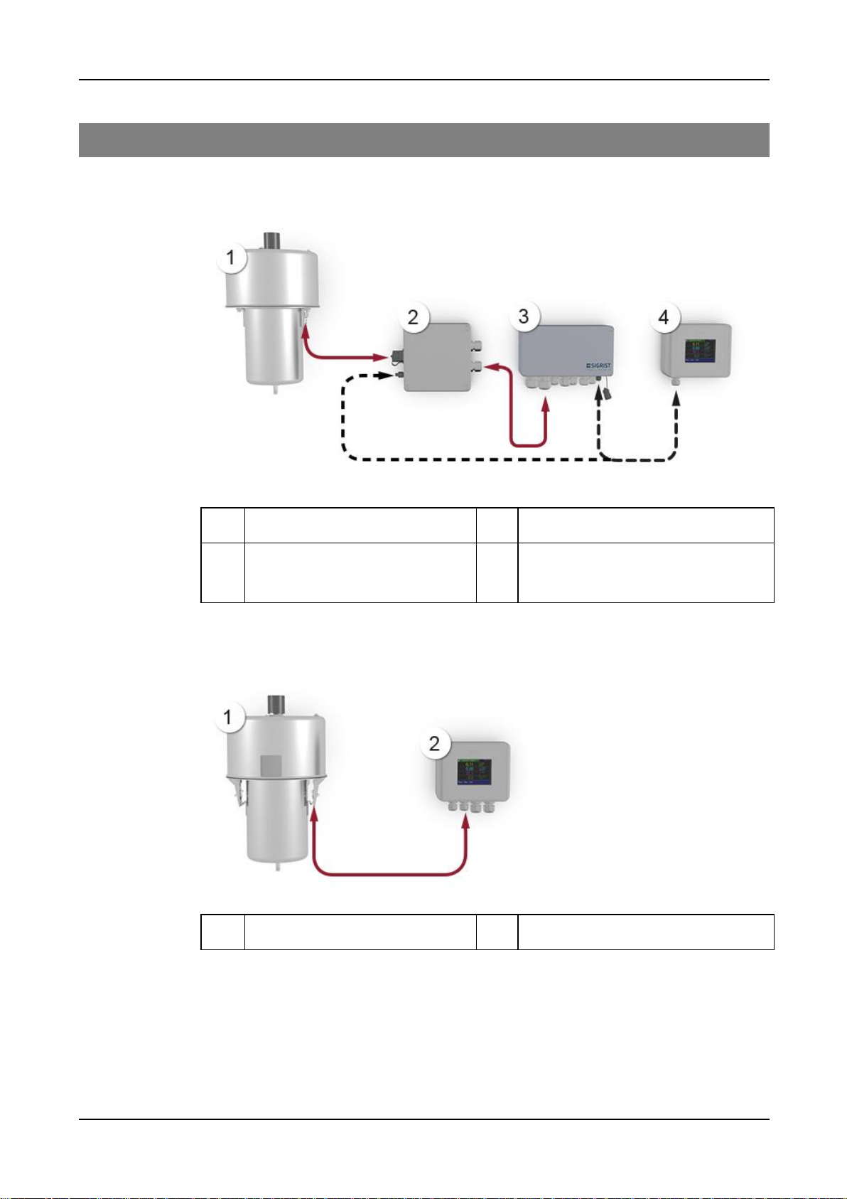
2.1 Overview of a measuring point with SIPORT 2
Figure 1: Overview of a measuring point with VisGuard 2 In-situ
VisGuard 2 In-situ
Connection box (optional)
SIPORT 2 connection box
SICON-C portable control unit, can be
connected to the SIPORT 2 or connec-
tion box via cable
2.2 Overview of a measuring point with SICON only
Figure 2: Overview of a measuring point with VisGuard 2 In-situ connected to the SICON
VisGuard 2 In-situ
SICON (M) control unit
Instruction Manual VisGuard 2 Instrument overview
12 14162E/2
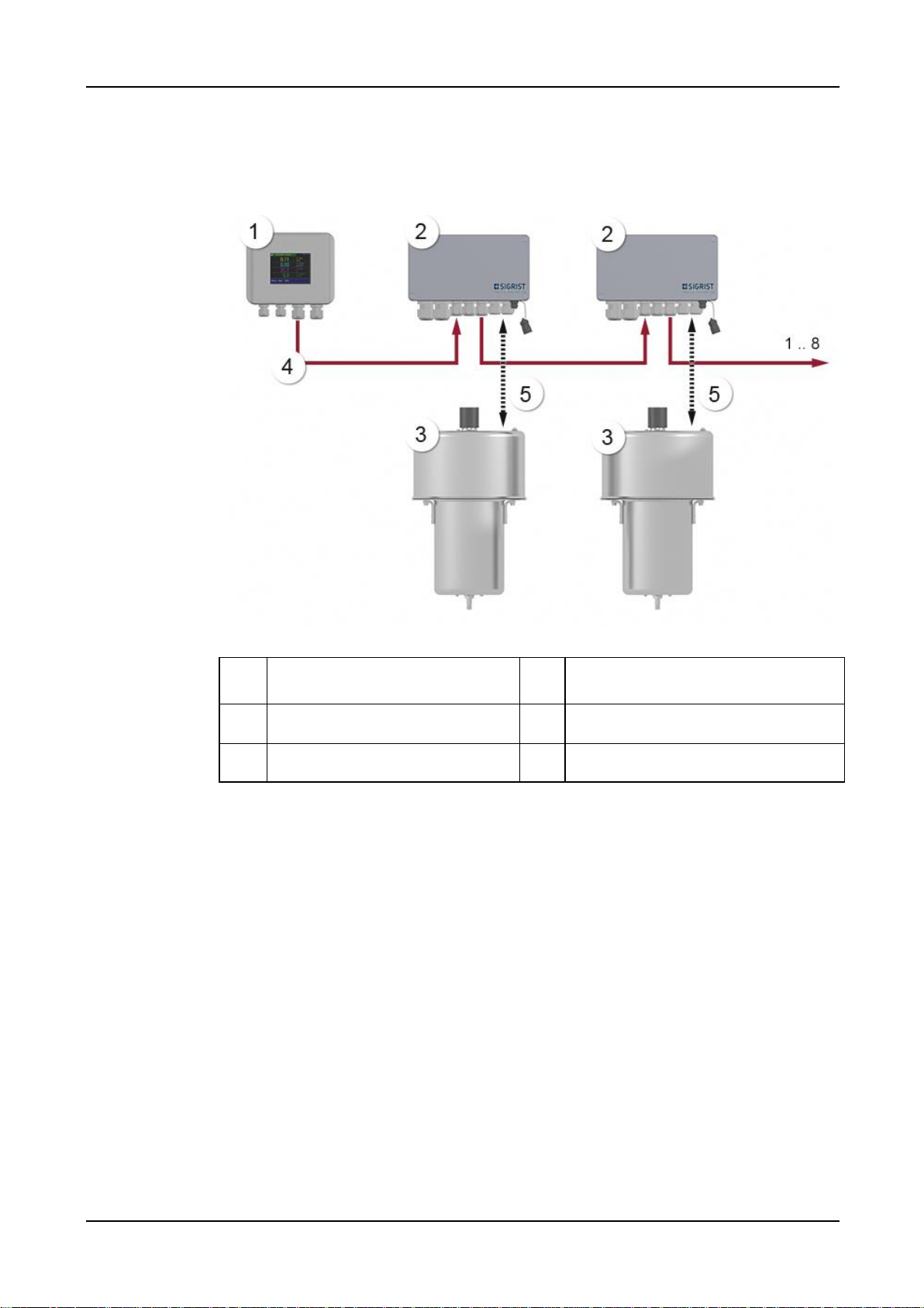
2.3 Overview of a multiple measuring point with SICON M
Up to eight VisGuard 2 instruments can be connected and operated on the SICON M.
Figure 3: Overview of a multiple measuring point with VisGuard 2
SICON M multi-channel control
unit
SIPORT 2 connection box with in-
tegrated Modbus RTU with repeater
VisGuard 2 In-situ (1 .. 8)
RS-485 bus connection
Connection cable to VisGuard 2

Instrument overview Instruction Manual VisGuard 2
14162E/2 13
2.4 Designation of the components
2.4.1 Designationof the VisGuard 2
The VisGuard 2 is fitted with the following rating plate:
Figure 4: Designation of the VisGuard 2
Manufacturer
Country of origin
Product name
Serial number
Date of manufacture
Service voltage
Frequency range
Power
Observe the Instruction Manual
Observe the disposal information
A red sticker is attached to the VisGuard 2 (arrow). This dis-
tinguishes it from instruments with a similar appearance.
Figure 5: Red sticker for identifying the VisGuard 2

Instruction Manual VisGuard 2 Instrument overview
14 14162E/2
2.4.2 Designationof the SICON(M/-C)
The SICON (M/-C) control unit is fitted with the following rating plate:
Figure 6: Designation of the SICON-C
Manufacturer
Country of origin
Product name
Serial number
Date of manufacture
Service voltage
Frequency range
Power
Observe the Instruction Manual
Observe the disposal information

Instrument overview Instruction Manual VisGuard 2
14162E/2 15
2.4.3 Designationof the SIPORT 2
The SIPORT 2 connection box is fitted with the following rating plate:
Figure 7: Rating plate on SIPORT 2
Manufacturer
Country of origin
Product name
Serial number
Date of manufacture
Service voltage
Frequency range
Power
Observe the Instruction Manual
Observe the disposal information
Instruction Manual VisGuard 2 Instrument overview
16 14162E/2
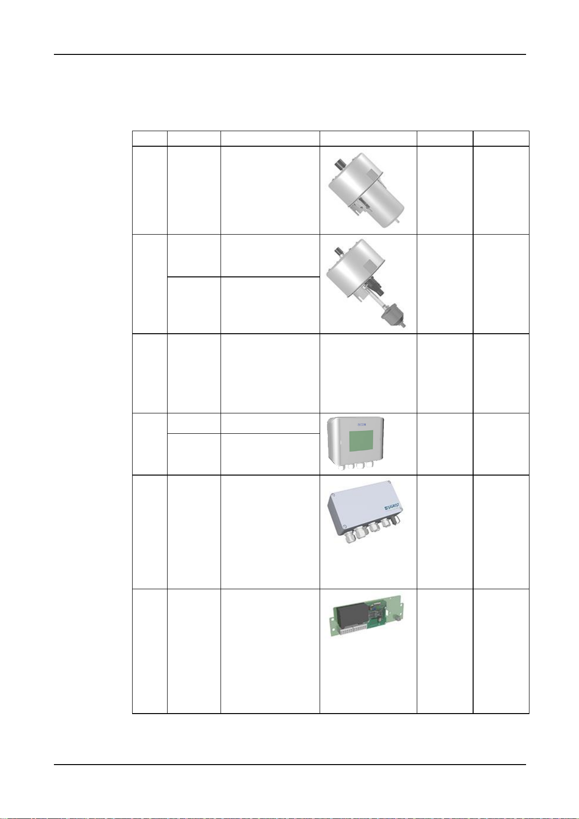
2.5 Scope of supply and accessories
2.5.1 Standard scope of supplyfor the VisGuard 2
Pcs.
Art. no.
Name
View
In-situ
Extractive
1
120688
VisGuard 2 In-situ
X
1
120686
VisGuard 2 Extractive
(extraction length 30
.. 500 m)
X
120687
VisGuard 2 Extractive
(extraction length up
to 30 m)
1
-
Gas sampling system
GSS5: 0 .. 5 m
GSS30: 5 .. 30 m
GSS500: 30 .. 500 m
GSSM: Multiple
sample
X
1
118342
SICON control unit
X
X
119040
SICON M control
unit
1
SIPORT 2 connection
box with integrated
Option: Instrument
socket with protec-
tion cover 120387
X
X
120287
Profibus DP
120288
StromRel
120289
Modbus RTU
121118
Profinet IO
1
Connection print for
SIPORT 2 without
housing, with in-
tegrated
X
X
120389
Profibus DP
120390
StromRel
120391
Modbus RTU
121119
Profinet IO

Instrument overview Instruction Manual VisGuard 2
14162E/2 17
Attached documents:
Pcs.
Doc. no.
Name
View
Variant
1
14162
Instruction Manual
German
French
English
1
14165
Reference Manual
German
English
1
14166
Brief Instructions
German
French
English
2.5.2 Optional scope of supplyfor the VisGuard 2
PCS.
ART. NO.
NAME
VIEW
VARIANT
1
120290
SICON-C portable
control unit
1
112677
Checking unit
1
120342
Junction box
1
112408
Sample heater
25 W/230 VAC

Instruction Manual VisGuard 2 Instrument overview
18 14162E/2
PCS.
ART. NO.
NAME
VIEW
VARIANT
1
120802
Sample heater
24 VDC/10 W
Reference Manual
1
118358
High-temperature
cable, 8-pin,
length by meter,
for connection to
the SIPORT 2
1
120393
High-temperature
cable, 8-pin incl.
connector, L = 1.5
m, for connection
to the SIPORT 2
with connection
socket
1
118637
High-temperature
cable, 4-pin,
length by meter,
for SICON connec-
tion
1
120790
Current/digi. input
for SIPORT 2
For SIPORT 2
1
118442
Profibus DP inter-
faces print
For SICON (M)
1
118445
Modbus RTU inter-
faces print
For SICON (M)
1
121121
Profinet IO inter-
faces print
For SICON (M)
1
119796
HART module
For SICON (M)
1
119130
4-way current
output
For SICON (M)

Instrument overview Instruction Manual VisGuard 2
14162E/2 19
PCS.
ART. NO.
NAME
VIEW
VARIANT
1
119795
4-way current in-
put
For SICON (M)
1
119045
24 VDC mains de-
vice
20 W, IP66, input
100 to 240 VAC
2.6 Technical data for the VisGuard 2
General:
Data
Values
Measuring principle
Scattered light measurement
Measurement span
0 .. 1000 PLA or 0 .. 3000 mE/m
Wavelength
880 nm
Resolution
± 0.001 mE/m
Reproducibility
± 0.06 mE/m, or ± 1%
Reaction time
2 s
Measuring angle
30 °
Sample pressure
Max. ± 3000 Pa (± 30 mbar)
Ambient temperature
-30 .. 55 °C
Ambient humidity
0 .. 100 % rel. humidity
VisGuard 2 photometer:
Data
Values
Service voltage
24 VDC
Power consumption
7 W + optional heater 10 W
Weight
6.5 kg (In-situ), 5.0 kg (Extractive)
Protection class
IP66 (with splash guard only)
Photometer material
Stainless steel 1.4435 / 1.4571
Cable standard
High-temperature cable:
Length: as needed
Type: 4 x 2 x 0.80 mm2
FE180, E30-E90
Dimensions
ca. Ø 209 mm x 366 mm
Detailed dimension sheet according to Section 16

Instruction Manual VisGuard 2 Instrument overview
20 14162E/2
SICON-C portable control unit:
Data
Values
Service voltage
24 VDC
Power consumption
1.3 W
Display
¼ VGA with touchscreen
Resolution: 320 x 240 pixels with 3.5" diagonal
Protection class
IP66
Weight
0.6 kg
Dimensions
160 x 152 x 60 mm
Detailed dimension sheet according to Section 16
Housing material
ABS
SIPORT 2 connection box:
Data
Values
Service voltage
100 .. 240 VAC; 47 .. 63 Hz
Power consumption
25 W (maximum)
VisGuard 2 In-situ, with sample heater: 24 W / 45 VA
VisGuard 2 In-situ, without sample heater: 12 W / 27 VA
Interfaces
Profibus DP, Modbus RTU with repeater, StromRel module;
optional: Current/Digi. Input, Profinet IO
Maximum operating
altitude
2,000 m above sea level
Protection class
IP66
Weight
1.3 kg
Dimensions
220 x 155 x 91 mm
Detailed dimension sheet according to Section 16
Housing material
Glass-fiber reinforced polyester
Table of contents


