6
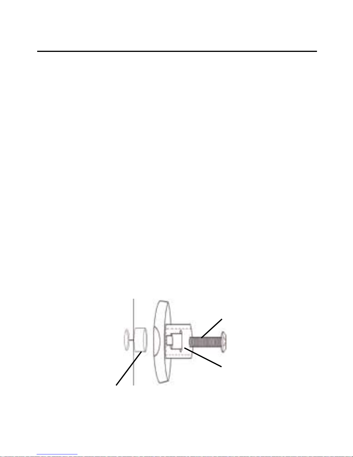
3. Engage the key hole nut into the key hole slot.
4. Puttensionontheassemblybygentlypullingback
on the speaker mount post while tightening the
5/8"-32x5/8"machinescrew,seeFigure4onpage
5.
5. The key hole nut will engage on the housing in the
key hole slot.
6. If the post does not tighten securely against the
housing, it will be necessarry to use the M5 x 1/8"
plastic washer as a spacer under the head of the
5/8"-32x5/8"machinescrew,seeFigure4onpage
5.
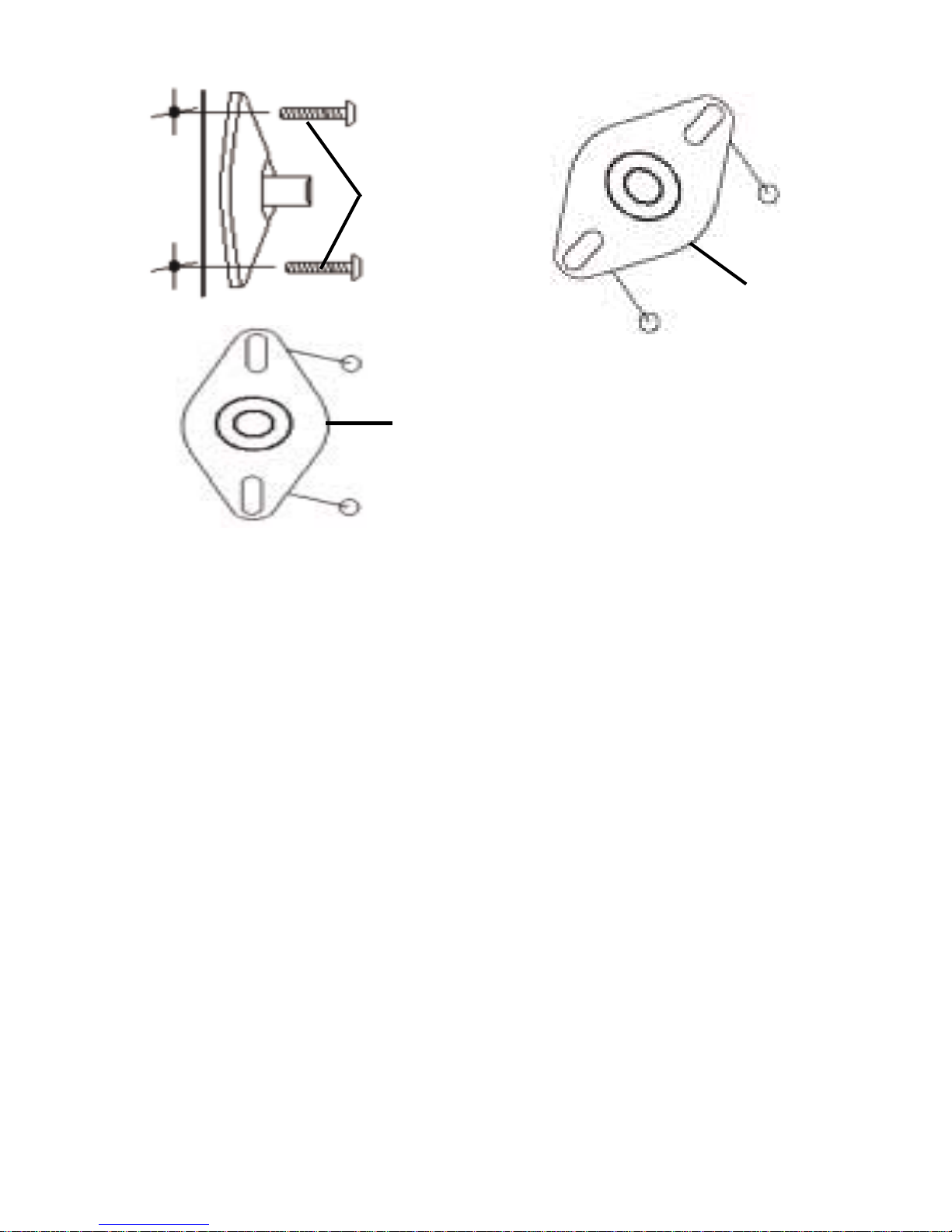
2/4 Hole Mounting
1. Findthebestmountingconfigurationthatmatches
yourspeakerenclosure. Four-holemountpatterns
can be accomodated by positioning the speaker
plate diagonally, see Figure 5 on the next page.
2. Usingthe1/4"-20x1/2"machinescrews,installthe
speakerplateandsecurethespeakerenclosure, see
Figure 5 on the next page.