Silva s15 User manual

VHF DSC S15 CLASSE D DSC, NAVTEX, GPS

Operation Manual S15
Page 1
Chapter Description Page
1 Introduction 3
2 Front Panel Description 4
2.1 Front 4
2.2 Back Of Unit 5
2.3 LCD Display 6
3 Fist Microphone/Controller 7
3.1 Soft Keypad (0 – 9) 7
4 General Operation 9
4.1 Dual Watch 9
4.2 Full Scan 10
4.3 Memory Scan 10
4.4 High / Low RF Output Power Selection 10
4.5 Squelch Control 11
4.6 Volume Control 11
4.7 Channel 16 12
4.8 Channel Select 12
4.9 Memory Channel Select 12
5 Receiving A DSC Call 13
5.1 Routine Calls 13
5.2 Urgency And Safety Calls 13
5.3 Group Calls 14
5.4 Distress Alert 14
6 Sending A DSC Call 16
6.1 Distress Calls 16
6.2 Routine Calls 17
6.3 Urgency And Safety Calls 18
6.4 Group Calls 19
7 Log View 20
7.1 Review Routine Log 20
7.2 Review Distress Log 21
7.3 View NAVTEX Messages 22

Operation Manual S15
Page 2
8 Settings 24
8.1 Backlight & Keypad Lighting Adjustment 24
8.2 Contrast Adjustment 24
8.3 Speaker Selection 25
8.4 Tone Selection 25
9 DSC Setting 26
9.1 MMSI Setting 26
9.2 Set Group ID 27
9.3 Set Date And Time 28
9.4 Set Manual Position 28
9.5 Set Called Channels 29
9.6 Set Directory Of Called MMSI And Vessel Names 31
10 NAVTEX Setting 33
10.1 Station Selection 33
10.2 Message Selection 34
10.3 Clear All NAVTEX Logs 34
11 GPS Navigation Setting 36
11.1 Set Waypoint Number (Go To Waypoint) 36
11.2 Set Waypoint 37
11.3 Review Waypoint 38
11.4 Navigation View 38
11.5 Insert Waypoint 40
11.6 Delete Waypoint 41
12 Technical Specifications 42
12.1 Receiver 42
12.2 Channel 70 Monitor General Specification 43
12.3 Transmitter 43
12.4 NAVTEX 43
12.5 GPS 43
13 VHF Marine Channel Chart 44
14 Installation 45
14.1 Unit Installation 45
14.2 Antenna Installation Recommendations 46
15 Parts Provided 48
16 Warranty 48
17 Certificate Of Conformity 49

Operation Manual S15
Page 3
1. Introduction
The S15 is a Class-D Digital Selective Calling (DSC) VHF marine transceiver
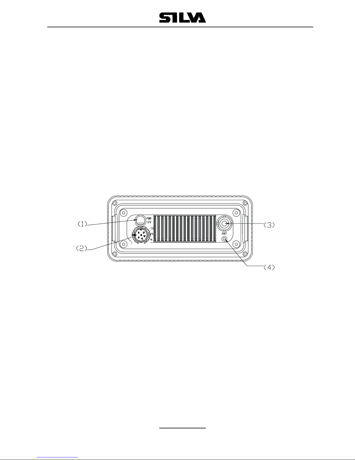
with built in GPS capability (position, waypoints, course and speed over the
ground) if connected with GPS input from either a GPS navigator or smart
antenna. The S15 also has full NAVTEX message display capability when
interfaced with a suitable NAVTEX antenna/receiver unit. The transceiver is a
25-watt, frequency modulated waterproof transmitter/receiver for applications
in the 156.025 - 162.550MHz band.
The S15 supports the latest GMDSS requirement for non-SOLAS vessels
from the international maritime organization (IMO).
The S15 will enable you to make digitally selected calls, which are quicker
and simpler to make then conventional voice calls using channel 16. Should
a distress urgency or safety situation occur, with the S15 you can quickly
raise an alert, indicating your identity, your position and automatically
establish distress communication on the emergency voice channel.
The S15 will display received NAVTEX messages and the ID of received
messages from the NAVTEX receiver. NAVTEX is a worldwide coastal telex
broadcast system. The broadcast stations transmit navigational warning,
meteorological warnings, Search And Rescue (SAR) information and other
data for ships sailing within their service range.
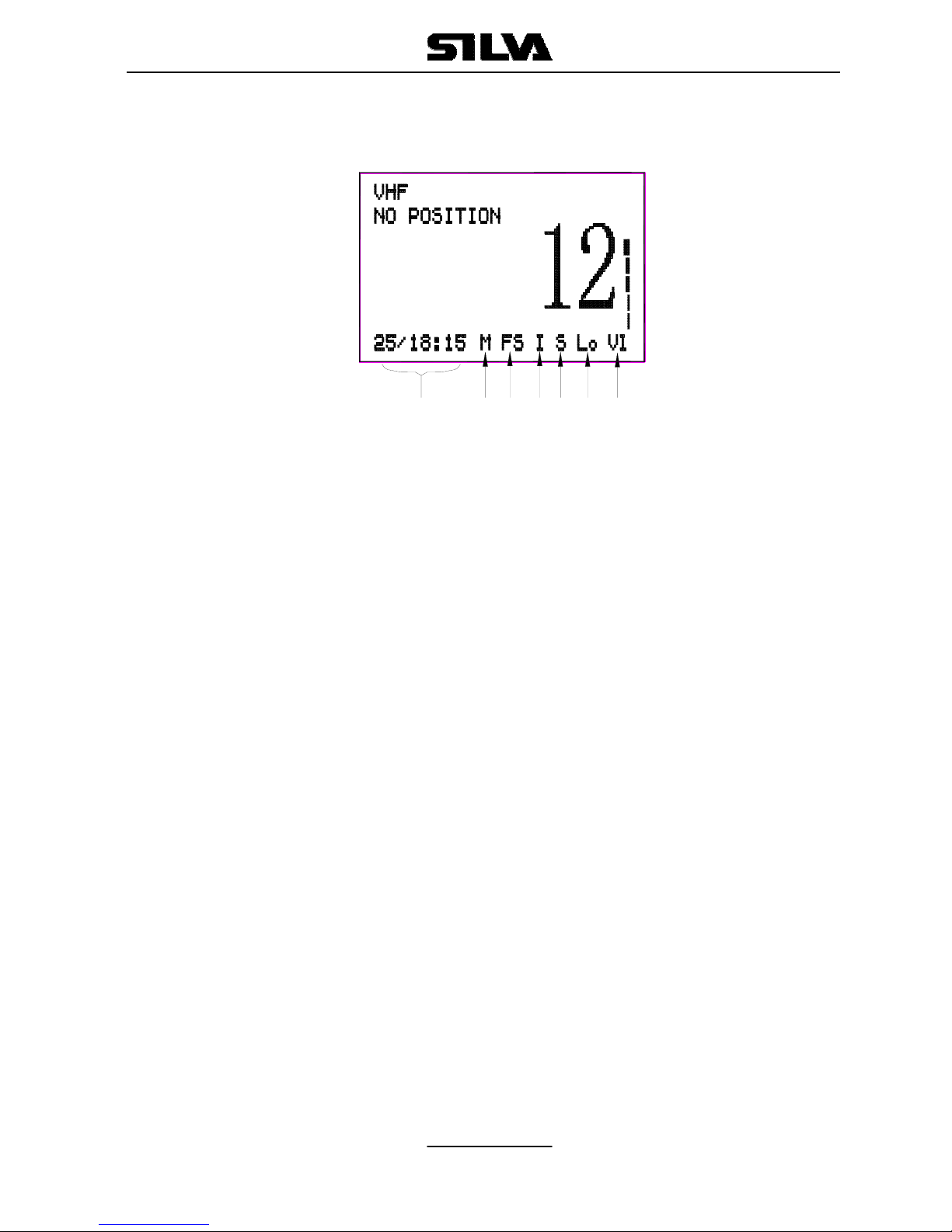
If the S15 is connected with a GPS, it will also display your vessels position
and Universal Time Coordinated (UTC) and it can also give you the COG
(Course Over Ground), SOG (Speed Over Ground), BTW (Bearing To
Waypoint) and DTW (Distance To Waypoint) of your vessel.
Silva operates a policy of continual development and reserves the right to
alter and improve the specification of their products without notice.

Operation Manual S15
Page 4
2. Front Panel Description
2.1 Front
1. POWER SWITCH (ON)
Press the (ON) button once on the front panel of the S15.
To switch off, press (ON) again the S15 switch off.
2. CHANNEL MEMORY KEY (M+)
The function of this key is to add or delete the currently selected channel
from the scan memory.
3. CLEAR KEY (CLR)
Stops current task and returns to the main screen.
4. SQUELCH MODE SELECTION KEY (SQ)
5. VOLUME CONTROL MODE SELECTION KEY (VOL)
6. FUNCTION SELECT KEY (F)
Press this key once to enter the function selection mode; the LCD will
display the function menu. The selectable functions are DUAL WATCH,
FULL SCAN, MEMORY SCAN, H/L (high/low) POWER and DIM. Press
the (F) key again to confirm and change to selected function screen.
7. DOWN KEY (▼)
Selects the desired channel, squelch control level or volume control
level. Each press selects the next lower channel number or level. Press
and hold to scroll down through all of the channels.
8. CHANNEL 16 KEY (16)
Used to immediately return to channel 16 from any channel or function.

Operation Manual S15
Page 5
9. UP KEY (▲)
Selects the desired channel, squelch control level or volume control
level. Each press selects the next higher channel, number or level. Press
and hold to scroll up through all of the channels.
10. LIQUID CRYSTAL DISPLAY (LCD)
Dot Matrix display, giving up to 8 lines of information.
11. SPEAKER
12. DISTRESS CALL BUTTON
The distress button as located under a protective, spring loaded cover
that must be lifted before the button can be pressed.
13. FIST MICROPHONE/CONTROLLER CORD.
2.2 Back
1. POWER CORD CONNECTOR
2. GPS, NAVTEX & EXTERNAL SPEAKER CONNECTOR
3. ANTENNA CONNECTOR
4. VENTILATION HOLE
Should mist be discovered on the inside of the LCD Display, remove
this screw and ventilate the unit until the mist is cleared. Upon
completion, the screw should be fully tightened to prevent water
seepage. Insert the screw and tighten once again. Note: To ensure
your S15 maintains its waterproof feature, please make sure the
waterproof plastic washer is properly inserted before the screw;

Operation Manual S15
Page 6
2.3 LCD Display
GROUP 1
VL Volume control is activated, the Bar indicates the volume level.
Sq Squelch control is activated, the Bar indicates the squelch level.
Mu Appears when the squelch opens.
RX The radio is in receptive state (RX) and when receiving a signal.
TX The radio is transmitting (TX).
GROUP 2
Hi Indicates TX maximum output power is 25W.
Lo Indicates TX maximum output power is 1W.
GROUP 3
S Indicates the displayed channel is a simplex channel.
D Indicates the displayed channel is a duplex channel.
GROUP 4
I Indicates the international channels are selected.
K Indicates the international channels with added channel M1 and
M2 are selected.
GROUP 5
DW Indicates dual watch scanning operation.
FS Scans every channel of current channel list.
MS Scans the selected memory channels.
GROUP 6
M Indicates the displayed channel is a selected memory scanning
channel.
GROUP 7
Date/hours: minutes
765 43 21

Operation Manual S15
Page 7
3. Fist Microphone/Controller
The fist mike/controller has the microphone, Push to Talk (PTT) switch
and Soft-keypad as illustrated below:
3.1 SOFT-KEYPAD (0 - 9)
The telephone style keypad ITU 0 – 9 / A - Z is used for entering numeric
data. When required, the keys will automatically switch to character mode
allowing letters, numbers and punctuation characters to be entered.
Repeatedly pressing a key will cycle through the characters available on
that key.
1
press — A D G J M P T W 0
2
press , B E H K N Q U X (
3
press ° C F I L O R V Y )
4
press / ? ! : ” ’ S & Z %
5
press 1 2 3 4 5 6 7 8 9 0

Operation Manual S15
Page 8
ENTER KEY (ENT)
Confirms the action.
CLEAR KEY (CLR)
Stop tasks and returns to main screen or returns to the last screen.
◄/ ►Key Moves the cursor position when setting.
▲/ ▼KEY
Use to select working channel (Up or Down). Can also be used to select
stored working channels. Allows viewing of next or previous message
and selection next or previous item.
PTT BUTTON
Keys the transmitter allowing you to transmit a message.
(CALL) KEY.
Activates ‘CALL’ menu.

Operation Manual S15
Page 9
4. General Operation
The S15 is switched on by pressing the (ON) key once. If a GPS receiver
and a NAVTEX receiver have been connected to the S15, the main
screen will be as bellow:
Press the (F) key on the front panel once to enter function selection
mode. The FUNCTION SELECTION screen will be displayed as follows:
Press the ▲or ▼key to move the ►symbol on the screen to the
required function (DUAL WATCH, or FULL SCAN, or MEMORY SCAN,
or H/L POWER and DIM), then press (F) key confirm. Dual watch, Full
Scan, Memory Scan, H/L Power or DIM can be selected, the relevant
screen will be displayed. Press (F) key again to restore normal operation,
and press (CLR) key to change to main screen.
4.1 DUAL WATCH (DW)
Dual watch enables the radio to scan between the selected channel and
priority channel (normally CH16). When in dual watch mode, the DW
indicator will appear on the bottom line of the LCD.

Operation Manual S15
Page 10
Note that the radio will not transmit, nor will alternative channels be able
to be selected while in dual watch mode. To restore normal operation
press (F) key again or press channel (16) key.
4.2 FULL SCAN (FS)
This function scans through each channel sequentially until a signal is
detected above the squelch level set. Once the signal ends or drops
below the squelch level, the radio will continue scanning. Since the scan
function stops on channels where a signal is detected, the radio will be
locked. If you want the scan continue, press ▲key once. When in Full
Scan mode, FS will appear on the bottom line of LCD.
Note that the radio will not transmit, nor will alternative channels be able
to be selected while in Full Scan mode. To restore normal operation
press (F) key or press channel (CH16) key to go to back to VHF screen.
4.3. MEMORY SCAN (MS)
The Memory Scan operates in the same way as the Full Scan, except
that it will only scan channels that have been entered into the Scan
Memory. If no channels have been entered into the memory then this
function will not available. See 4.9, Page 12.
When in memory scan mode, “MS” will appear on the bottom line of the
LCD.
4.4 HIGH/LOW RF OUTPUT POWER SELECTION
Press ▲or ▼key to move the ►symbol on the FUNCTION
SELECTION screen to required function “H/L POWER”, then press the
(ENT) key for selection of low or high power, then the “Hi” or “Lo” will
appear on the bottom line of the LCD.

Operation Manual S15
Page 11
4.5 SQUELCH CONTROL
In the main screen, press the (SQ) key on the front panel, the screen will
be changed to the VHF screen. Squelch is used to adjust the receiver
muting threshold (squelch) level. When pressed, the squelch level bar
and “Sq” symbol will appear at the right side of the screen as follows.:
To cut out weaker signals, press ▲key to increase the squelch until the
background interference noise disappears. To receive weaker signals
press ▼key to decrease the squelch.
4.6 VOLUME CONTROL (VOL)
Press the (VOL) key on the front panel, the volume control screen will be
displayed. The level Bar and character “Vl” will appear on the right side of
the screen as bellow:
Press ▲key to increase the volume. Press ▼key to reduce the volume.

Operation Manual S15
Page 12
4.7 CHANNEL 16 (16)
Pressing (16) key will automatically select channel 16 on high power. Any
active function (Dual watch scanning, DSC setting, log view, NAVTEX
GPS setting etc) will be cancelled.
4.8 CHANNEL SELECT (▲/ ▼)
Press ▲key to go up through the channels. Press ▼key to go down
through the channels.
Channel Selection Shortcut:
Select the desired channel directly from the main screen by pressing the
channel number on the fist microphone/controller, and then press “ENT”
to confirm.
4.9 MEMORY CHANNEL SETTING (M+)
Pressing the (M+) key will add the currently selected channel into the
scan memory. When operating in VHF receiver mode, if the key is
pressed the screen will show “M” on the bottom right of the LCD
indicating that the channel has been entered into the scan memory. By
pressing the (M+) key again, the “M” will be deleted indicating that the
channel is not a memory scan channel

Operation Manual S15
Page 13
5. Receiving A DSC Call
When a DSC call is received, the radio will switch to the call log screen to
display the details of the call and ring or sound the alarm depending on
the nature of the call. The procedures that follow describe how to handle
the types of calls that can be received.
5.1 ROUTINE CALLS
When a Routine call is received, the screen will show the details of the
call, where it is from and working channel as follows. Also an alarm will
sound.
Press the (ENT) key on the fist/mike keypad, an acknowledgement will
be sent to caller and the radio will be automatically switched to working
channel for normal voice communication. The “*” will disappear when the
call has been acknowledged.
When looking back at routine call logs, if there is a “*” symbol on the
screen, you can press (ENT) key to send an acknowledgement. After
acknowledgement, the “*” will disappear.
5.2 URGENCY AND SAFETY CALLS
The procedures for urgency and Safety calls are very similar. An urgency
call will sound the distress alarm and switch the radio to Channel 16. A
safety call will sound a normal ring and switch the radio to the specified
working channel as follows:

Operation Manual S15
Page 14
Press the (ENT) key to stop the alarm (or ringing), and then listen for the
voice message.
5.3 GROUP CALLS
When a Group call is received, the radio will sound an alarm and display
the details of the call, indicating whom it is from and the working channel
as follows:
Press (ENT) key to stop the alarm, then listen for the voice message or
speak.
5.4 DISTRESS ALERT
If a Distress Alert or a Distress Relay is received from another vessel, an
alarm will sound and the Radio will switch to channel 16. The screen will
show the details of the Distress Alert or Distress Relay, the MMSI of the
vessel, the nature of the distress, it’s position and time, Mute the alarm
by pressing (ENT) key and maintain a listening watch on channel 16 for
the distress messages. Press (CLR) key to clear the display.

Operation Manual S15
Page 15

Operation Manual S15
Page 16
6. Sending A DSC Call
Making a DSC call is very simple. First choose the call type (Routine,
Safety, Urgency, Group or Distress Alert). If required, enter the
destination and working channel and then send the call by pushing (ENT)
key on the fist microphone/controller. The digital signal will be sent out in
under a second, containing the vessels ID and the call type.
In order for the radio to function, your MMSI (Maritime Mobile Service
Identifier) number will need to be entered. This number can be obtained
from your local radio communications authority. For the group call, the
group ID will need to be entered also.
6.1 DISTRESS ALERT – THIS CALL SHOULD ONLY BE MADE IF
THE VESSEL IS IN A DISTRESS SITUATION, AND LIFE IS IN
DANGER.
Making a Distress Alert call is very simple. Lift the protective cover and
press (DIST) key on the front panel. The Distress Alert screen will be
displayed as follows:
If time permits, press the ▲or ▼keys on front panel or ◄or ►keys on
first/mic to select the nature of the distress. There are 10 categories
recognized as Distress Alert situations, which are: fire, flooding,
collision, grounding, listing, sinking, adrift, abandoning, piracy and
man overboard. There is also a default undesignated category, which
is used if no category is selected here.

Operation Manual S15
Page 17
Press and hold the (DIST) key for about five seconds. A countdown to
the transmission will be displayed then an alarm will sound.
The Distress Alert transmission contains the following data:
1. The vessel’s MMSI;
2. The vessel’s position (either from the NMEA0183 input, or manually
entered);
3. The time (from NMEA or Manual input);
4. The nature of the distress.
After the Distress Alert has been sent, the Radio will automatically tune to
channel 16 and the Radio will repeat the Alert approximately every four
minutes until either an acknowledgement is received, or (CLR) key is
pressed (it is not recommended that the Distress Alert is cancelled
manually by pressing (CLR) key unless you are requested to do so by
the rescue authorities).
While the Distress Alert remains active, an intermittent alarm will continue
to sound approximately once every 25 seconds.
When an acknowledgement is received from the Rescue Co-ordination
Centre, this will cancel the Distress Alert transmission from the Radio and
automatically switch the Radio to the required working channel. The
subsequent Rescue Co-ordination will be performed using the voice-
working channel.
6.2 ROUTINE CALL
To make a routine call, press (CALL) key on the fist
microphone/controller to select Routine call. The screen is as follows:

Operation Manual S15
Page 18
Then enter a called vessel’s MMSI number with the keypad and select a
working channel by pressing the ▲or ▼key on the keypad from the
channel list.
Press (ENT) key and the Radio will send a routine call. Then the radio
will change to following screen and wait for a reply.
When a reply is received, it will sound a tone and automatically set to the
specified working channel. A voice call can then be made in the normal
way.
6.3 URGENCY CALL AND SAFETY CALL
Press (CALL) key on the fist microphone/controller keypad to select
safety call or urgency call as follows respectively.
Press the (ENT) key, the screen is as follows respectively.

Operation Manual S15
Page 19
Press the (ENT) key again to make the call, or press (CLR) for cancel.
When the call is sent, the radio will be set to the working channel. Allow a
few seconds for the stations receiving the call to switch to the working
channel. Then make a normal voice call on the selected working channel.
6.4 GROUP CALL
If a group ID has been set up for the called Radio. A call can be made to
other members of the group.
Press the (CALL) key on the keypad to select the group call screen as
follows:
Select a working channel from the channel list by pressing the ▲or ▼
keys on the keypad.
Press (ENT) key to send the call, allow a few seconds for the other
members of the group to reach the radios (all VHF radios in the group
should automatically switch to selected working channel upon
acknowledgement), then make a normal voice call.
Table of contents