Yaesu FT-991 User manual

HF/VHF/UHF All Mode TrAnsceiVer
FT-991
operATing MAnUAl
YAESU MUSEN CO., LTD.
Tennozu Parkside Building
2-5-8 Higashi-Shinagawa, Shinagawa-ku, Tokyo 140-0002 Japan
YAESU USA
6125 Phyllis Drive, Cypress, CA 90630, U.S.A.
YAESU UK
Unit 12, Sun Valley Business Park, Winnall Close
Winchester, Hampshire, SO23 0LB, U.K.


Page 1
FT-991 OperaTing Manual
Table of ConTenTs
Table of Contents ......................................................... 1
Accessories & Options ................................................. 3
Supplied Accessories................................................ 3
Available Options ..................................................... 4
Adjusting the Clock.................................................. 5
Resetting the Microprocessor................................... 5
Installation and Interconnections............................... 6
Antenna Considerations ........................................... 6
About Coaxial Cable ................................................ 6
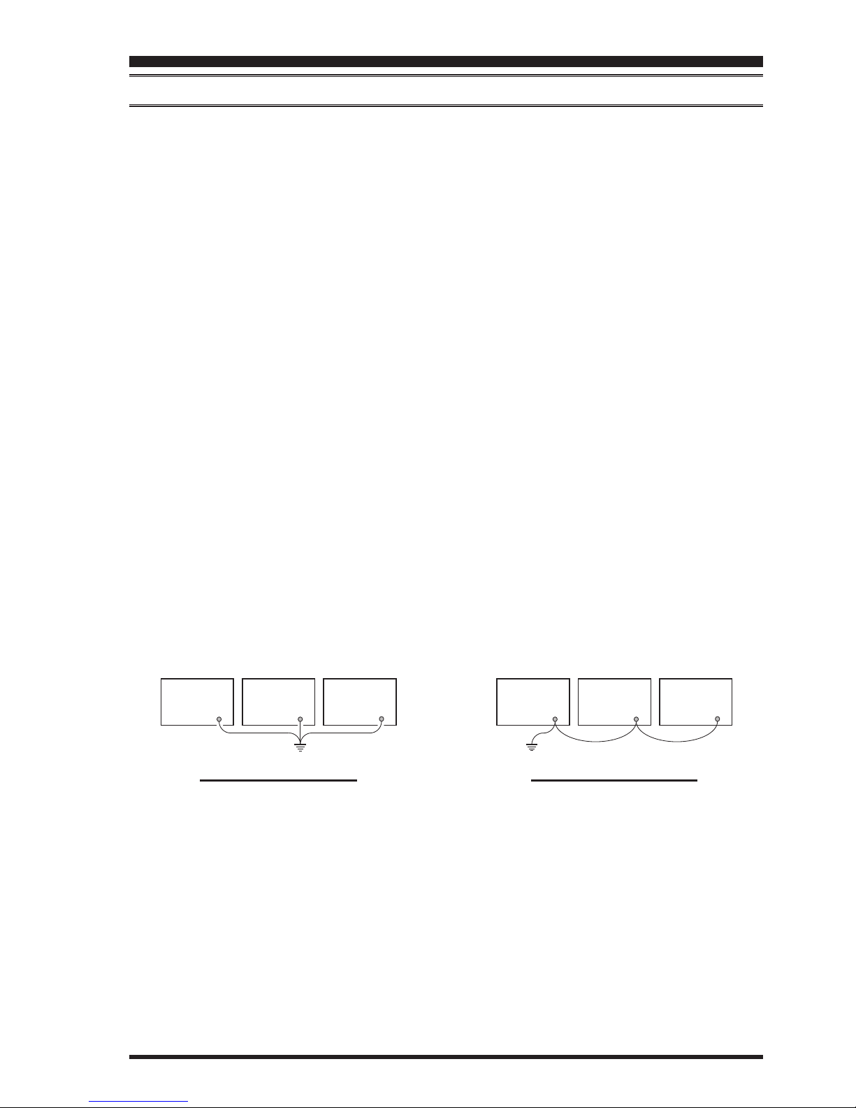
Grounding................................................................. 7
Connection of Antenna and Power Cables............... 8
Connection of Microphone and Headphone............. 9
Key, Keyer, and Computer-Driven Keying
Interconnections ..................................................... 10
VL-1000 Linear Amplier Interconnections.......... 11
Interfacing to Other Linear Ampliers................... 12
Front Panel Controls & Switches ............................. 13
Display Indications..................................................... 18
Rear Panel................................................................... 21
MH-31A8J Microphone Switches............................. 23
Optional FH-2 Switches............................................. 24
Basic Operation: Receiving on Amateur Bands...... 25
Operation on 60-Meter (5 MHz) Band (U.S. version
only) ....................................................................... 28
CLAR (Clarier)Operation ................................... 29
LOCK..................................................................... 30
DIMMER ............................................................... 30
VFO COLOR ......................................................... 30
Band Stack Operation............................................. 31
C.S (Custom Switch).............................................. 31
Convenience Features................................................ 31
SCOPE ................................................................... 32
More Frequency Navigation Techniques ............... 33
Receiver Operation (Front End Block Diagram)... 34
ATT (
AttenuAtor
).................................................. 35
Interference Rejection ............................................... 35
IPO (Intercept Point Optimization)........................ 36
IF Noise Blanker (NB)Operation .......................... 37
CONTOUR Control Operation .............................. 38
IF SHIFT Operation (SSB/CW/RTTY/PKT
Modes).................................................................... 39
WIDTH (IF DSP Bandwidth)Tuning (SSB/CW/
RTTY/DATA Modes)............................................. 40
NARROW (NAR)One-Touch IF Filter
Selection................................................................. 41
IF NOTCH Filter Operation (SSB/CW/RTTY/
DATA/AM Modes)................................................. 42
Digital NOTCH Filter (DNF)Operation................ 43
Digital Noise Reduction (DNR)Operation............ 43
Tools for Comfortable and Effective Reception ...... 44
RF Gain .................................................................. 44
Audio Peak Filter ................................................... 45
AGC (Automatic Gain Control)............................. 46
Adjustable Receiver Audio Filter........................... 47
SSB/AM Mode Transmission .................................... 48
ATU Operation ....................................................... 50
Using the Automatic Antenna Tuner ........................ 50
About ATU Operation ............................................ 51
P
ArAmetric microphone equAlizer
(SSB/Am/Fm
mode
) ...................................................................... 52
Enhancing Transmit Signal Quality......................... 52
Using the Speech Processor (SSB Mode).............. 54
Adjusting the SSB Transmitted Bandwidth (SSB
Mode) ..................................................................... 55
Voice Memory (SSB/AM/FM modes: Requires
optional DVS-6 and FH-2)................................ 56
Transmitter Convenience Features .......................... 56
VOX (SSB/AM/FM Modes: Automatic TX/RX
Switching using Voice Control) ............................. 58
MONITOR (SSB/AM/FM modes)......................... 59
Split-Frequency Operation ..................................... 60
Setup for Straight Key (and Straight Key emulation)
Operation................................................................ 61
CW Mode Operation ................................................. 61
Using the Built-in Electronic Keyer....................... 62
CW Spotting (Zero-Beating).................................. 65
CW Convenience Features ........................................ 65
CW Delay Time Setting ......................................... 66
Contest Memory Keyer (Using the Optional FH-2
Remote Control Keypad) ....................................... 67
Basic Operation ...................................................... 72

Page 2
FT-991 OperaTing Manual
Table of ConTenTs
FM Mode Operation .................................................. 72
Repeater Operation................................................. 73
Tone Squelch Operation ......................................... 74
Memory Operation .................................................... 75
Convenient Memory functions............................... 75
QMB (Quick Memory Bank)................................. 75
Standard Memory Operation.................................. 76
Memory Groups ..................................................... 80
Operation on Alaska Emergency Frequency: 5167.5
khz (U.S. Version Only) ............................................. 81
VFO and Memory Scanning ..................................... 82
VFO Scanning........................................................ 82
Memory Scan ......................................................... 83
PMS (Programmable Memory Scanning) ............... 84
RTTY (Radio Teletype)Operation ........................... 85
Example of Connecting RTTY Communications
Device..................................................................... 85
DATA (PSK)Operation ............................................. 86
Example of Data Communications Device ........... 86
Menu Mode................................................................. 87
Specications .............................................................. 91

Page 3
FT-991 OperaTing Manual
aCCessories & opTions
Supplied AcceSSorieS
Hand Microphone (MH-31A8J)1 pc A07890001
DC Power Cord 1 pc T9025225
Spare Fuse (25A) 1 pc Q0000074
Operating Manual 1 pc
Warranty Card 1 pc

Page 4
FT-991 OperaTing Manual
Accessories & options
AvAilAble OptiOns
MD-200A8X Ultra-High-Fidelity Desktop Microphone
MD-100A8X Desktop Microphone
YH-77STA Lightweight Stereo Headphone
FH-2 Remote Control Keypad
VL-1000/VP-1000 LinearAmplier/ACPowerSupply
FC-40 ExternalAutomaticAntennaTuner
FP-1030A ExternalPowerSupply(13.8VDC25A)
CT-118 VL-1000LinearAmplierConnectionCable
CT-39A PacketInterfaceCable
CTCable(MDIN10P-BareWire2m) LinearAmplierConnectionCable(P/NT9207451)
MD-200A8X YH-77STA FH-2
VL-1000/VP-1000 FC-40

Page 5
FT-991 OperaTing Manual
ON/OFF switch
MENU(SETUP) button
A
M button
LCD
before You begin
reSetting the MicroproceSSor
reSetting MeMorieS
(
only
)
Use this procedure to reset (clear) the previously stored
Memory channels, without affecting any conguration
changes you may have made to the Menu settings.
1. Press the front panel ON/OFF switch to turn the
transceiver off.
2. While holding the A
Mbutton in, press and hold
in the front panel ON/OFF switch to turn the trans-
ceiver on. Once the transceiver comes on, you may
release the buttons.
Menu reSetting
Use this procedure to restore the Menu settings to their
factory defaults, without affecting the memories you
have programmed.
1. Press the front panel ON/OFF switch to turn the
transceiver off.
2. While holding the MENU(SETUP) button in, press
and hold in the front panel ON/OFF switch to turn
the transceiver on. Once the transceiver comes on,
you may release the buttons.
Full reSet
Use this procedure to restore all Menu and Memory set-
tings to their original factory defaults. All Memories will
be cleared by this procedure.
1. Press the front panel ON/OFF switch to turn the
transceiver off.
2. While holding the FAST and LOCK buttons in,
press and hold in the front panel ON/OFF switch to
turn the transceiver on. Once the transceiver comes
on, you may release the buttons.
LOCK button
FAST button
ON/OFF switch MENU(SETUP) button
ON/OFF switch
AdjuSting the clock
Use the following procedure to adjust the clock shown at the top right of the LCD display.
1. Press and hold the MENU(SETUP) button.
2. Touch [TIME/DATE] on the LCD.
3. Enter the present time with the number keys on the
LCD, then touch [ENT].
4. Touch [DATE] on the LCD to switch the screen.
5. Enter month, day, and year with the number keys on
the LCD, then touch [ENT].
6. Touch [BACK] on the LCD to return to the setup
mode display.
7. Press the MENU(SETUP) button to return to the
radio operation display.

Page 6
FT-991 OperaTing Manual
AntennA conSiderAtionS
The FT-991 is designed for use with any antenna system providing a 50 Ohm resistive impedance at the desired operat-
ing frequency. While minor excursions from the 50-Ohm specication are of no consequence, if the Standing Wave Ra-
tio (SWR) present at the Antenna jack is greater than 3:1, the transceiver’s Automatic Antenna Tuner may not be able to
reduce the impedance mismatch to an acceptable value.
Every effort should be made to ensure that the impedance of the antenna system be as close as possible to the specied
50-Ohm value. Note that the “G5RV” type antenna does not provide a 50-Ohm impedance on all HF Amateur bands. An
external wide-range antenna coupler must be used with this antenna type.
Any antenna to be used with the FT-991 must be fed from the transceiver with 50 Ohm coaxial cable. Therefore, when
using a “balanced” antenna such as a dipole, remember that a balun or other matching/balancing device must be used to
ensure proper antenna performance.
The same precautions apply to any additional (receive-only) antennas connected to the antenna jacks. if your receive-
only antennas do not have impedance near 50 Ohms at the operating frequency, you may need to install an external an-
tenna tuner to obtain optimum performance.
About coAxiAl cAble
Use high-quality 50-Ohm coaxial cable for the lead-in to your FT-991 transceiver. All efforts at providing an efcient
antenna system will be wasted if poor quality, lossy coaxial cable is used. This transceiver utilizes standard “M” (“PL-
259”) type connectors.
insTallaTion and inTerConneCTions
typicAl pl-259 inStAllAtion

Page 7
FT-991 OperaTing Manual
insTallaTion and inTerConneCTions
proper ground connection
GND
Linear
Amplifier
GND
TNC
GND
Transceiver
GND
Transceiver
GND
Linear
Amplifier
GND
TNC
"Daisy Chain"
GND
Linear
Amplifier
GND
TNC
GND
Transceiver
GND
Transceiver
GND
Linear
Amplifier
GND
TNC
"Daisy Chain"
iMproper ground connection
grounding
The FT-991 transceiver, like any other HF communications apparatus, requires an effective ground system for maxi-
mum electrical safety and best communications effectiveness. A good ground system can contribute to station efciency
in a number of ways:
It can minimize the possibility of electrical shock to the operator.
It can minimize RF currents owing on the shield of the coaxial cable and the chassis of the transceiver. such cur-
rents may lead to radiation, which can cause interference to home entertainment devices or laboratory test equip-
ment.
It can minimize the possibility of erratic transceiver/accessory operation caused by RF feedback and/or improper
current ow through logic devices.
An effective earth ground system may take several forms. for a more complete discussion, see an appropriate RF engi-
neering text. The information below is intended only as a guideline.
Typically, the ground connection consists of one or more copper-clad steel rods, driven into the ground. If multiple
ground rods are used, they should be positioned in a “V” conguration and bonded together at the base of the “V” which
is nearest the station location. Use a heavy, braided cable (such as the discarded shield from type RG-213 coaxial cable)
and strong cable clamps to secure the braided cable(s) to the ground rods. Be sure to weatherproof the connections
to ensure many years of reliable service. Use the same type of heavy, braided cable for the connections to the station
ground bus (described below).
Inside the station, a common ground bus consisting of a copper pipe of at least 25 mm diameter should be used. An al-
ternative station ground bus may consist of a wide copper plate (single-sided circuit board material is ideal) secured to
the bottom of the operating desk. Grounding connections from individual transceivers, power supplies, and data com-
munications devices (TNCs, etc.) should be made directly to the ground bus using a heavy, braided cable.
Do not “Daisy-Chain” ground connections from one electrical device to another and thence to the ground bus. This
method may nullify any attempt at effective radio frequency grounding. See the drawing below for examples of proper
grounding techniques.
Inspect the ground system - inside the station as well as outside - on a regular basis to ensure continued performance
and safety.
Besides following the above guidelines carefully, note that household or industrial gas lines must never be used in an
attempt to establish an electrical ground. Cold water pipes may, in some instances, help in the grounding effort, but gas
lines represent a signicant explosion hazard, and must never be used.

Page 8
FT-991 OperaTing Manual
connection oF AntennA And power cAbleS
Please follow the outline in the illustration regarding the proper connection of antenna coaxial cables, as well as the DC
power cable. The DC power connector for the
FT-991
must only be connected to a DC source providing 13.8 Volts DC (±10
%), and capable of at least 23 Amperes of current. Always observe proper polarity when making DC connection:
The RED DC power lead connects to the Positive (+) DC terminal.
The BLACK DC power lead connects to the Negative (–) DC terminal.
We recommend the use of the FP-1030A (USA market only) AC Power Supply. Other models of power supplies may
be used with the FT-991, but the 13.8 VDC input voltage, 23 Ampere current capability, and DC cable polarity guide-
lines described above must be strictly followed.
Note that other manufacturers may use the same type of DC power connections as does your FT-991 transceiver, how-
ever, the wiring conguration may be different from that specied for your transceiver. Serious damage can be caused if
improper DC connections are made; consult with a qualied service technician when in doubt.
The 100 V RF voltage (@100 W/50-ohm) is applied to the TX RF section of the transceiver while transmitting.
Do not touch the TX RF section absolutely while transmitting.
Permanent damage can result when improper supply voltage, or reverse-polarity voltage, is applied to the FT-
991. The Limited Warranty on this transceiver does not cover damage caused by application of AC voltage, re-
verse polarity DC, or DC voltage outside the specied range of 13.8 V ±10 %. When replacing fuses, be certain to use a
fuse of the proper rating. The FT-991 requires a 25 A blade fuse.
Advice:
Do not position the FT-991 in a location with direct exposure to sunshine.
Do not position the FT-991 in a location exposed to dust and/or high humidity.
Ensure adequate ventilation around the FT-991, to prevent heat build-up and possible reduction of performance due
to high heat.
Do not install the
FT-991
on an unstable desk or table. Do not place in a location where objects may fall onto it from above.
To minimize the possibility of interference to home entertainment devices, take all precautionary steps including
separation of TV/FM antennas from Amateur transmitting antennas to the greatest extent possible, and keep trans-
mitting coaxial cables separated from cables connected to home entertainment devices.
Ensure that the DC power cord is not subject to undue stress or bending, which could damage the cable or cause it to
be accidentally unplugged from the rear panel DC IN jack.
Be certain to install your transmitting antenna(s) so they cannot possibly come in contact with TV/FM radio or other
antennas, or with power or telephone lines.
insTallaTion and inTerConneCTions
Check the DC volt-
age and current rating
(+13.8 V, 23 A) of the power
supply before connecting to the
transceiver.
To prevent damage from
lightning, atmospheric elec-
tricity, electrical shock etc., please
provide a good earth ground.
Use a short,
thick, braided
cable to con-
nect your station
equipment to the
buried ground rod (or alternative earth
ground system).

Page 9
FT-991 OperaTing Manual
insTallaTion and inTerConneCTions
connection oF Microphone And heAdphone
DOWN
UP
+5V
MIC GND
MIC
PTT
GND
FAST

Page 10
FT-991 OperaTing Manual
key, keyer, And coMputer-driven keying interconnectionS
The FT-991 includes many features for the CW operator. These functions will be detailed in the “Operation” section
later. Besides the built-in Electronic Keyer, two key jacks are provided, one on the front and one on the rear panel, for
convenient connection to keying devices.
The Menu selections allow you to congure the front panel KEY jack according to the device you wish to connect. For
example, you may connect your keyer paddle to the front panel KEY jack, and use Menu item “018 F KEYER TYPE” for
paddle input.
The KEY jack on the FT-991 utilize “Positive” keying voltage. Key-up voltage is approximately +3.3V DC, and key-
down current is approximately 4 mA. When connecting a key or other device to the KEY jack, use only a 3-contact
(“stereo”) 1/4” phone plug; a 2-contact plug will place a short between the ring and (grounded) shaft of the plug, result-
ing in a constant “key-down” condition in some circumstances.
insTallaTion and inTerConneCTions

Page 11
FT-991 OperaTing Manual
DC 13.8 V
CT-58 ALC Cable (Option)
CT-58 Band Data Cable (Option)
144/430MHz Antenna HF/50MHz Antenna
Coaxial Cable (50Ω)
Connect to “INPUT 1” of the VL-1000
INPUT
BAND-DATA 1
ALC 1
TUN/LIN
REM/ALC
GND
GND
VP-1000
VP-1000 CONTROL
DC 48V IN
ANT 1
ANT 2
ANT 3
INPUT 1
ANT
144/430MHz
ANT
HF/50MHz
insTallaTion and inTerConneCTions
vl-1000 lineAr AMpliFier interconnectionS
Be sure that both the FT-991 and VL-1000 are turned off, and then follow the installation recommendations contained
in the illustration.
note:
Refer to the VL-1000 Operating Manual for details regarding amplier operation.
Do not attempt to connect or disconnect coaxial cables when your hands are wet.
To link the FT-991 and VL-
1000 Power switches, set the
VL-1000 REMOTE switch to
the “ON” position.
Set the front panel’s
INPUT switch to the
“INPUT1”.

Page 12
FT-991 OperaTing Manual
insTallaTion and inTerConneCTions
interFAcing to other lineAr AMpliFierS
note
The TX GND OUT pin (pin 2) of the TUN/LIN jack
is a transistor “open collector” circuit. It is capable of
handling positive relay coil voltages up to +60VDC
at 200 mA or +30 VDC at 1 A. If you plan to use
multiple linear amplifiers for different bands, you
must provide external band switching of the “Linear
Tx” relay control line from the “TX GND OUT” line
at the TUN/LIN jack.
The specied range for ALC voltage to be used with
the FT-991 is 0 to -4 Volts DC.
Amplier systems utilizing different ALC voltages
will not work correctly with the FT-991, and their
ALC lines must not be connected if this is the case.
iMportAnt note!
Do not exceed the maximum voltage or current rat-
ings for the “TX GND OUT” pin (pin 2) of the TUN/
LIN jack. This line is not compatible with negative
DC voltages, or AC voltages of any magnitude.
Most amplifier control relay systems require only
low DC voltage/current switching capability (typi-
cally, +12V DC at 25 ~ 75 mA), and the switching
transistor in the FT-991 will easily accommodate
such ampliers.
DC 13.8 V
Linear Amplifier Connection Cable
(Option: T9207451)
144/430MHz Antenna HF/50MHz Antenna
Coaxial Cable (50Ω)
Connect to “INPUT” of the linear amplifier
INPUT
TUN/LIN
GND
GND
GND
TX GND
EXT ALC
GND
INPUT
ANT
ANT
144/430MHz
ANT
HF/50MHz

Page 13
FT-991 OperaTing Manual
ON/OFF Switch
Press and hold in this switch for one second to turn
the transceiver on. Similarly, press and hold in this
switch for one second to turn the transceiver off.
KEY Jack
This 1/4-inch, 3-contact jack accepts a CW key or
keyer paddles (for the built-in electronic keyer), or
output from an external electronic keyer. Pinout is
shown on page ##. Key up voltage is +3.3 V DC,
and key down current is 4 mA. This jack may be
configured for keyer, “Bug”, “straight key”, or
computer keying interface operation via Menu item
“011 F CW KEYER” (see page ##).
note:
You cannot use a 2-contact plug in this jack (to do so
produces a constant “key down” condition).
PHONES Jack
A 1/4-inch, 3-contact jack accepts either monaural or
stereo headphones with 2- or 3-contact plugs. When
a plug is inserted, the loudspeaker is disabled.
note:
When wearing headphones, we recommend that you
turn the AF Gain levels down to their lowest settings
before turning power on, to minimize the impact on
your hearing caused by audio “pops” during switch-
on.
MIC Jack
This 8-pin jack accepts input from a microphone uti-
lizing a traditional YAESU HF transceiver pinout.
fronT panel ConTrols & swiTChes
4
3
2
1
5
789
6

Page 14
FT-991 OperaTing Manual
fronT panel ConTrols & swiTChes
F(M-LIST) Button
F
This button is used to display function list. The fol-
lowing functions can be accessed from the function
list:
NAR/WIDE, NB, AGC, ATT, IPO, NOTCH, CONT,
DNR, DNF, SHIFT, WIDTH, MOX, VOX, MONI,
MIC-EQ, PROC, BK-IN, SPEED, SQL
M-LIST
Pressing and holding this button will show the mem-
ory channel list. ........
MENU(SETUP) Button
MENU
This button is used to access the Menu system. The
various transceiver characteristics may be config-
ured.
SETUP
Pressing and holding this button will .......
BAND Button
These keys allow one-touch selection of the desired
Amateur band (1.8 ~ 50 MHz).
The keys may also be used for direct entry of a de-
sired operating frequency during VFO operation.
MODE Button
This button selects the operating mode. The selec-
tions available are:
LSB, USB, AM, CW (LSB), CW (USB), FM,
RTTY (LSB), RTTY (USB), C4FM, DATA (LSB),
DATA (USB), DATA (FM)
MULTI Knob
This knob allows you to select the Menu items and
settings.

Page 15
FT-991 OperaTing Manual
A=B Button
Press this button momentarily to transfer the fre-
quency or memory channel data, from VFO-A to
VFO-B, overwriting any previous contents in VFO-
B. Use this key to set both VFO-A and VFO-B to the
same frequency and mode.
A/B Button
Pressing this button momentarily, exchanges the
frequency or memory channel data, of VFO-A and
VFO-B.
RCL/STO Button
RCL (Recall)
Pressing this button, recalls one of up to ve Quick
Memory Bank memories for operation.
STO (Store)
Pressing this button copies the contents (frequency,
mode, bandwidth, FM repeater offset, and CTCSS
settings) of VFO-A, into consecutive QMB Memo-
ries.
TUNE Button
This is the on/off switch for the FT-991’s Automatic
Antenna Tuner.
Pressing this button momentarily places the antenna
tuner in line between the transmitter nal amplier
and the antenna jack (The “TUNER” icon will ap-
pear in the display). Reception is not affected.
Pressing and holding in this button for two seconds,
while receiving in an amateur band, activates the
transmitter for a few seconds while the automatic
antenna tuner rematches the antenna system imped-
ance for minimum SWR. The resulting setting is au-
tomatically stored in one of the antenna tuner’s 100
memories for instant automatic recall later when the
receiver is tuned near the same frequency.
Pressing this button momentarily, while the Tuner is
engaged, will take the Automatic Antenna tuner out
of the transmit line.
note:
When the Automatic Antenna Tuner is tuning itself,
a signal is being transmitted. Therefore, be certain
that an antenna or dummy load is connected to the
selected antenna jack before pressing and holding in
the TUNE button to start antenna tuning.
fronT panel ConTrols & swiTChes
13 14 15 19
20
10 11 16 1712 18
21

Page 16
FT-991 OperaTing Manual
fronT panel ConTrols & swiTChes
C.S Button
Press this button momentarily to directly recall a fa-
vorite Menu Selection.
To program a Menu selection to the C.S button,
press the MENU(SETUP) button to enter the
Menu. Select the Menu item you want to set as
the short cut. Press the C.S button, then press the
MENU(SETUP) button; this will lock in the select-
ed Menu item as the short cut.
TXW (TX Watch)Button
Pressing and holding this button lets you monitor the
transmit frequency when split frequency operation is
engaged. Release the button to return to normal split
frequency operation.
FAST Button
Pressing this button will change the tuning of the
Main Tuning Dial knob (VFO-A) to a higher step
rate.
When this function is activated, the “FAST” indica-
tor in the LED indicators area illuminates.
LOCK Button
This button toggles locking on/off for the Main Tun-
ing Dial knob (VFO-A). With “Lock” on, the Main
Tuning Dial knob can still be turned, but the fre-
quency will not change, and the “LOCK” indicator
in the LED indicators area illuminates.
CLAR Button
RX
Pressing this button activates the RX Clarier. This
will allow you to temporarily adjust the receive
frequency up to ±9.999 kHz with the CLAR/VFO-
Bknob. Press this button once more to return the
receiver to the original frequency; the Clarier offset
will be remembered, in case you want to use it again.
To cancel the Clarifier offset, press the [CLEAR]
button.
Pressing this switch during Split operation will
change the tuning rate of the CLAR/VFO-B knob
(VFO-B) to 100 Hz/step.
When this function is activated, the “FAST” indica-
tor in the LED indicators area illuminates.
TX
Pressing this button activates the TX Clarier, to al-
low offsetting the transmit frequency temporarily.
Press this button once more to return the transmit-
ter to the original frequency; the Clarifier offset
will be remembered, though, in case you want to
use it again. To cancel the Clarier offset, press the
[CLEAR]button.
V/M Button
This button toggles frequency control between VFO-
A and the memory system. In memory mode, “MEM”
(Memory Channel) will be shown in the display to
indicate the current selection. Pressing the V/M but-
ton displays the original memory frequency, and the
“MEM” will be displayed. Pressing it once more
returns frequency operation to VFO-A, and the icon
will no longer be displayed.
A
MButton
Pressing this button momentarily, displays the con-
tents of the currently-selected memory channel for
10 seconds.
Pressing and holding in this key for one second (until
the double beep) copies the current operating data
into the currently selected memory channel, over-
writing any previous data stored there.
SPLIT Button
Press this button to operate split frequency between
VFO-A (used for reception) and VFO-B (used for
transmission). If you press and hold in the SPLIT
button for one second, the “Quick Split” feature will
be engaged. VFO-B transmit will automatically be
set to a frequency 5 kHz higher than the VFO-A re-
ceive frequency, with the same operating mode. The
transceiver will operate in the Split mode.

Page 17
FT-991 OperaTing Manual
Main Tuning Dial Knob
This large knob adjusts the operating frequency of
VFO-A. Clockwise rotation of this knob increases
the frequency. Default tuning increments are 10 Hz
(CW, SSB), 50 Hz (RTTY/DATA), 100 Hz (AM/
FM). When the FAST button is pressed, the tuning
steps increases. The available steps are:
operAting Mode
LSB/USB/CW
AM/FM
RTTY/DATA
1 Step
10 Hz (100 Hz)
100 Hz (1 kHz)
5 Hz (100 Hz)
1 diAl rotAtion
10 kHz (100 kHz)
100 kHz (1 MHz)
5 kHz (100 kHz)
Numbers in parentheses indicate steps when the FAST button is On.
fronT panel ConTrols & swiTChes
CLAR/VFO-B Knob
During the VFO-A operation, this knob tunes the
Clarier offset frequency up to ±9.999 kHz.
During Split operation, this knob adjusts the operat-
ing frequency of VFO-B.
RF GAIN Knob
The
RF GAIN knob is the receiver RF gain control,
which adjusts the gain of the receiver RF and IF
amplier stages. This control is normally left in the
fully clockwise position.
AF GAIN Knob
The
AF GAIN knob sets the receiver audio volume
level. Typically, you will operate with this control set
between the 9 o’clock and 10 o’clock positions.
23
24
25
22

Page 18
FT-991 OperaTing Manual
displaY indiCaTions
Mode Indicator
Displays the current operating mode.
VFO-A Frequency Display
Shows the main band (VFO-A) frequency.
Tuning Offset Indicator
This indicates the relative offset of the CW-TUNE,
μ-TUNE, Clarier, etc.
CongurationIndicator
TUNER
This indicator appears when the internal Automatic
Antenna Tuner is activated.
VOX
This indicator appears when the automatic voice-
actuated transmitter switches in the SSB, AM, and
FM modes.
PROC
This indicator appears whenever the DSP Speech
Processor is activated.
MIC EQ
This indicator appears whenever the Three-Band
Parametric Microphone Equalizer is activated via
the Menu.
NAR
This indicator appears whenever the receiver’s
narrow IF DSP lter is engaged.
REC
This indicator appears while the optional Voice
Memory Unit is recording your voice message, or
the Contest Keyer is recording your CW keying.
PLAY
This indicator appears while the optional Voice
Memory Unit is playing back the recorded voice
message, or the recorded Contest CW keying.
[+]/[-]
During FM repeater operation, a negative frequen-
cy shift will be indicated by “[-]” while a positive
frequency shift will be indicated by “[+]”.
DNR
This indicator appears whenever the Digital Noise
Reduction feature is activated.
DNF
This indicator appears whenever the Digital Notch
Filter is activated.
LCD Display
Other manuals for FT-991
8
Table of contents
Other Yaesu Transceiver manuals

Yaesu
Yaesu FT-2980R User manual

Yaesu
Yaesu FT-80C - SERVICE User manual

Yaesu
Yaesu VX-150 User manual

Yaesu
Yaesu FT-857D User manual

Yaesu
Yaesu FT-277R User manual

Yaesu
Yaesu FTdx5000 Series User manual

Yaesu
Yaesu FT DX 9000 TFT User manual

Yaesu
Yaesu VX-8R User manual

Yaesu
Yaesu FTM-3200DR User manual

Yaesu
Yaesu FT2DR User manual

Yaesu
Yaesu FT DX 9000 CONTEST - 2 Manual

Yaesu
Yaesu FT-7800R Manual

Yaesu
Yaesu VX-1R User manual

Yaesu
Yaesu FTDX 1200 Series Product guide

Yaesu
Yaesu FTA-750 Spirit User manual

Yaesu
Yaesu FT-101EE User manual

Yaesu
Yaesu FTdx5000 Series Manual

Yaesu
Yaesu FTDX10 User manual

Yaesu
Yaesu FTDX101D User manual

Yaesu
Yaesu FT DX 1200 User manual