Sim2 RTX 45-55 Technical specifications

USE AND INSTALLATION
MANUAL
ENGLISH
RTX 45-55

IMPORTANT SAFETY INSTRUCTIONS
!
CAUTION
RISK OF ELECTROCUTION
DO NOT OPEN
Make sure not to overload the socket or any extension cord.
FortheDigiOpticalImageProcessoronlyusethepowersupply
provided or in any case a power supply approved by SIM2.
•Pay attention to the cables.
Arrange the cables so that they do not constitute an obstacle.
Also, keep them out of the reach of children.
Install the units as close as possible to the wall socket.Do not
tread on the power cables, make sure that they are not tangled
or jerked;do not expose them to heat sources;make sure they
do not form knots or bends. If the cables are damaged in any
way, stop using the system and call an authorised technician.
•Disconnect the device in the event of storms or when not
used.
To avoiddamagethatcouldbecausedbylightning strikinginthe
vicinity of your home, disconnect the units in the event of storms
or when the system is not going to be used for a long period.
•Avoid contact with liquids and exposure to humidity.
Do not use the units near water (sinks, tubs, etc.);do not place
objects containing liquids on top of or near the units and do not
exposethentorain,humidity, drops or sprays;donotusewater
or liquid detergents to clean them.
•Avoid overheating the units.
Do not block ventilation openings.Do not place the units near
heat sources such as stoves, radiators or other devices
(including amplifiers) that generate heat.Do not place the units
in a confined space (bookcase, shelves, etc.) that is not well
ventilated.
• Do not expose eyes to the intense light of the lamp.
Neverlook directly into the lamp throughtheventilationopening
when it is working.
Thiscoulddamageyoureyesight.Inthis respect, payparticular
attention to children.
•Position the unit on a stable surface.
To avoid serious injury and damage to things, make sure the
units are placed on a level, flat and stable surface from which
they cannot fall, tip over or slide.In this respect, pay particular
attention when they are placed on a trolley to be moved.Do not
to expose them to shocks.
•Do not put anything in the openings of the units.
Make sure that no object is placed inside the units. If this
happens,immediately disconnecttheunitfromthe powersupply
and call an authorised technician.
This symbol indicates the danger of possible electric
shock caused by uninsulated current inside the
product.
This symbol indicates the presence of important
instructions regarding use and maintenance of the
product.
•Read and keep this manual.
This manual contains important information on how to install
and use this device in an appropriate manner. Before use,
carefullyreadthesafetyrulesandinstructions.Keepthemanual
for all future reference.
•Avoid contact with the internal parts of the units.
Inside the units there are electrical parts fed with dangerous
voltage and parts that operate at high temperatures. Do not
opentheunits;contactauthorised personnel forall maintenance
and repair operations.
Opening the units will also invalidate the warranty.
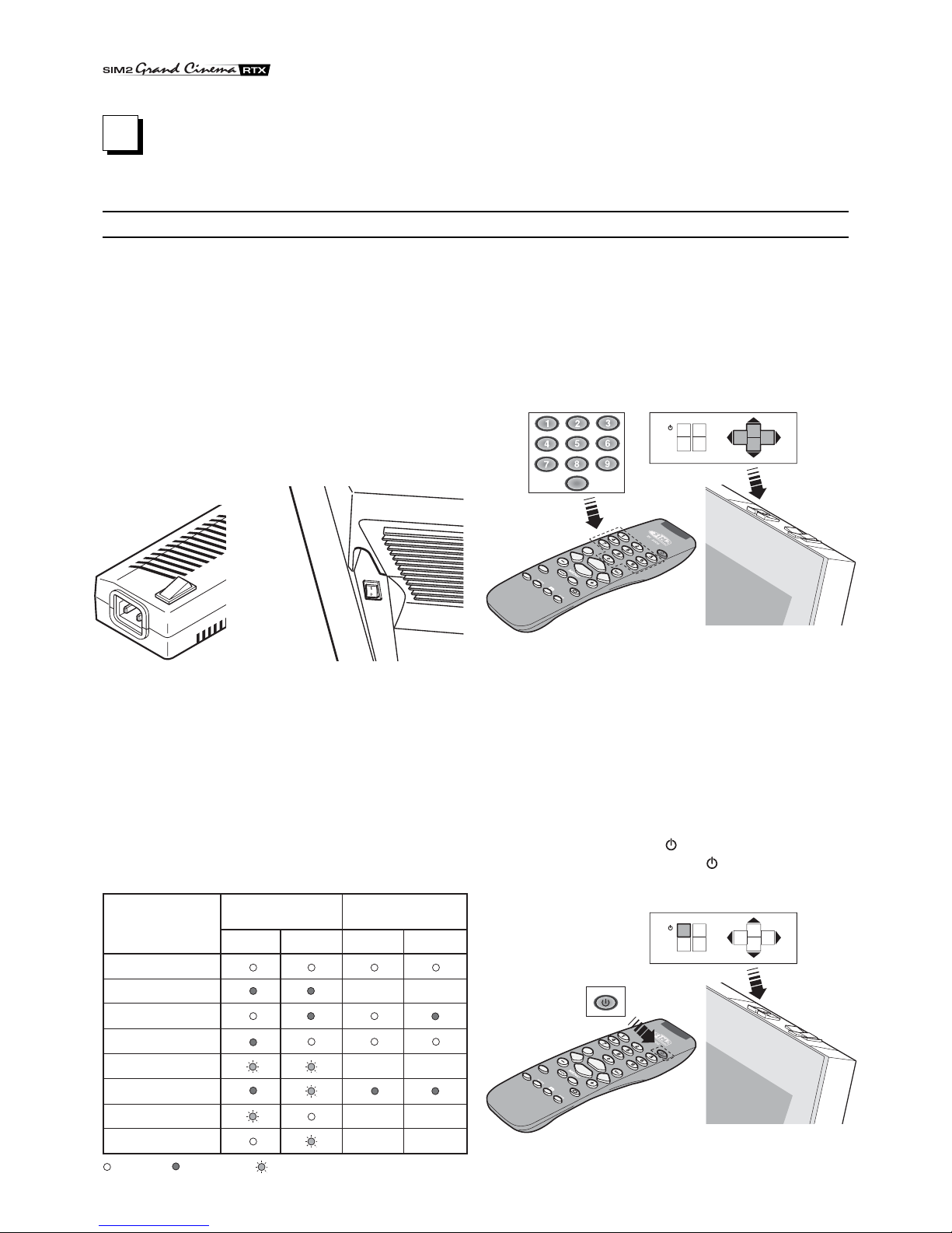
•Device for disconnecting the power supply.
The device for disconnecting the units from the electrical grid
is the feed cable plug. During installation make sure that the
feed cable plugs and the electrical system sockets are easily
accessible. To disconnect the units from the electric sockets,
pull the plug and not the cable.
•Only use the type of feed indicated.
Connect the units to an electrical grid with nominal voltage
between the values of 100-240 VAC, 50/60 Hz and provided
with grounding.If you are not sure of the type of power in your
home, consult a qualified technician.
TheRTXsystemconsistsoftwoparts,theDigiOpticalImage
Processor and the Display, connected by an optical fibre
cable.Below, the unit will be referred to as including the two
parts making up the system.
•Federal Communication Commission (FCC Statement)
This equipment has been tested and found to comply with the
limits for a Class B digital device, pursuant to Part 15 of the
FCC rules.
These limits are designed to provide reasonable protection
against harmful interference when the equipment is used in a
commercial environment.This equipment generates, uses and
can radiate radio frequency energy and, if not installed and
used in accordance with the instruction manual, may cause
harmful interference to radio communications. However, there
is no guarantee that interference will not occur in a particular
installation. If this equipment does cause harmful interference
to radio or television reception, which can be determinated by
turning the equipment off and on, the user is encuraged to try
to correct the interference by one or more of the following
measures:
- Reorient or relocate the receiving antenna
-Increasetheseparationbetweentheequipmentandreceiver.
- Connect the equipment into an outlet on a circuit different
from that to which the receiver is connected.
- Consult the dealer or an experienced radio/TV technician
for help.
•For customers in Canada
This Class B digital apparatus complies with Canadian ICES-
003.
•For customers in the United Kingdom
ATTENTION:This apparatus must be earthed.
The wires in this mains lead are coloured in accordance with
the following code:
Green-and-Yellow: Earth
Blue: Neutral
Brown: Live
As the colours of the wires in the mains lead of this apparatus
may not correspond with the coloured markings identifying the
terminals in your plug proceed as follows:
Thewirewhichis colouredgreen-and-yellow mustbeconnected
to the terminal in the plug which is marked by the letter
E or by the safety earth symbol or coloured green or green-
and-yellow.
The wire which is coloured blue must be connected to the
terminal which is marked with the letter N or coloured black.
The wire which is coloured brown must be connected to the
terminal which is marked with the letter L or coloured red.

TABLE OF CONTENTS
INTRODUCTION .......................................................................................................................4
1 INSTALLATION.............................................................................................. 6
CONNECTING THE TWO UNITS..............................................................................................6
CONNECTING THE VIDEO SOURCES.................................................................................... 7
Video .................................................................................................................................7
S-Video ................................................................................................................................7
COMPONENT/RGBS ..........................................................................................................7
Graphics RGB......................................................................................................................9
DVI-D .................................................................................................................................9
RS232 Control .....................................................................................................................9
Optical fibre link ...................................................................................................................9
2 USE.............................................................................................................. 10
TURNING ON AND OFF .........................................................................................................10
KEYPAD ...............................................................................................................................11
REMOTE CONTROL...............................................................................................................11
ON SCREEN MENU................................................................................................................12
Inputs ...............................................................................................................................12
Main Menu .........................................................................................................................13
Picture ...............................................................................................................................13
Image ...............................................................................................................................14
Set-up ...............................................................................................................................15
Info ............................................................................................................................... 15
Quick Menus ......................................................................................................................15
Messages ..........................................................................................................................15
MAINTENANCE ANDTROUBLESHOOTING .........................................................................16
Maintenance and cleaning.................................................................................................16
More common problems ....................................................................................................16
3ADDITIONAL INFORMATION ..................................................................... 18
TECHNICAL SPECIFICATIONS..............................................................................................18
DIMENSIONS..........................................................................................................................20
STRUCTURE OF THE ON SCREEN MENUS ........................................................................21

4
INTRODUCTION
Thank you for choosing the GrandCinema RTX system from
SIM2!
The RTX system integrates the signal processing ability of the
DigiOptical Image Processor with the faithful reproduction of a
DLP™ technology Display, putting the two units in
communication with each other by means of an optical fibre
connection.

5
DLP and DMD are registered trademarks of Texas Instruments.
DCDi is a registered trademark of Faroudja, a division of Genesis Microchip, Inc.
The DigiOptical Image Processor, ideally placed near the
sources,canacquireand process a wide rangeof videosignals,
in order to send them to the Display by means of the optical
fibre connection.
Its complement of inputs (2 CompositeVideo inputs, 2 S-Video
inputs,upto 4 Component or RGB inputs, 2 graphic RGB inputs
and 1 DVI-D input) allows connection to a wide variety sources,
bothanalogueanddigital:DVD players,VCRs,satelliteandcable
receiverboxes, computers,videogameconsoles,video cameras,
etc.
The signal processing it performs allows excellent reproduction
of a wide range of input signals, from interlaced video to high
definition and graphics.
Theconversion of interlaced video signals to progressivesignals,
donethroughuseoftherenownedDCDi™technology, produces
fluid, natural images free of flicker and steps along the diagonal
lines.
The faithful reproduction of signals at higher resolutions (such
as high definition video and graphics) occurs without loss of
information or reduction of image sharpness thanks to its high
ability to acquire signals at high pixel rates.
Adaptation of the input signal resolution to that of the Display
occurs without altering image quality through a wide range of
aspect ratios, including several definable by the user.
All adjustments relevant to the image can be performed with the
remotecontrolwiththeaidof the OnScreenDisplay;alternatively,
the unit can be controlled by a domestic automation system
through the serial port.
The Display, with its elegant and original design, produces an
imageusingthevery latestTexasInstrumentsDLP™technology
(1280x720 pixel DMD™ panel with 12°technology), a
proprietary, dust-sealed optical system, a new six-segment
colour wheel and a new concept Fresnel lens. All to provide an
image without half-measures, with definition, sharpness,
colorimetry and contrast equal to the renowned front projectors
of SIM2’s GrandCinema product line.
The connection between the two units occurs through a cable
containing three optical fibres which allow transmission of the
digitalsignalfromtheDigiOpticalImageProcessortotheDisplay
and control signals in both directions.
Transmission occurs without interference or attenuation over
distances of up to 500 m (1,640 ft).
Moreover, the flexibility and reduced diameter of the cable allow
maximum freedom in installing the system in your home.

6
CONNECTINGTHETWO UNITS
The RTX system consists of two distinct units (the DigiOptical
Image Processor and the Display), each of which equipped with
a power cable and connected to each other by a 20 m (65.6 ft)
optical fibre cable.
The ideal place for the DigiOptical Image Processor is the shelf
of a cabinet or on a rack (its dimensions are compatible with a
19" rack).Make sure that the support surface is stable and that
the unit has sufficient space around it for adequate ventilation
(at least 3 cm [1.2 in]).
The unit is powered by an external power supply that provides
a voltage of +7 VDC; the unit’s power switch is on the power
Display
Alimentatore
DigiOptical
Image Processor
Remote Control
1.5 V AAA-
type batteries
Power cables
Europe, UK, US (x2)
DigiOptical
Image Processor
Cable with
three optical fibres
Instruction
Manual
DIGIOPTICAL IMAGEPROCESSOR
O
I
DigiOptical Image
Processor Power Supply
1 INSTALLATION
The RTX system of SIM2 comprises the elements listed below
(Fig.1):
•the Display
•the DigiOptical Image Processor
•the remote control
•the DigiOptical Image Processor power supply
•three power cables for the Display
•three power cables for the DigiOptical Image Processor
•the cable with three optical fibres for the connection between
the DigiOptical Image Processor and the Display
•4 1.5 V AAA-type batteries for the remote control
•the use and installation manual
If some of the accessories are missing, contact your dealer as
soon as possible.
supply.
Connect the cable of the power supply to the POWER input
located on the rear panel (Fig. 4).
Only use the power supply provided with the system or a power
supply approved by SIM2.
The Display is designed to stand on the floor.Place it on a level,
flat surface so that it has sufficient space for ventilation and, to
avoid reflections, do not expose it to direct sunlight or intense
light sources.
Theconnection to the electrical grid is located on therearpanel,
like the power switch.
Adjust the rear feet to obtain the optimum viewing angle,
accordingtothedistanceandheightyousitinfrontoftheDisplay
(Fig.2).
Fig.1
The remote control provided (IR, operating with infrared rays),
allowscompletecontrolofthesystem.It is only forthe DigiOptical
Image Processor and the Display and can be used by pointing
at either of the two units without distinction, since each is
equipped with an IR receiver on its front.
The connection between the two units is made with a cable
containing three optical fibres, each terminating in an LC
connector.The standard cablelength (20 m, 65.6 ft),issufficient
Fig.2
Cavo
Fibra
Ferrula
Connettore
Tappo di
protezione
Punto di
sfiocco
Protection plug
Unravelling point
Unravelling poi
Cable
Connector
Fibre
Fig.3

7
CONNECTINGTHEVIDEO SOURCES
Connect the cables coming from the video sources, the serial
cable coming from the external device and the fibres for
connection to the Display, to the rear panel of the DigiOptical
Image Processor.
To obtain the best performance from the RTX system, connect
the various signal sources using good quality cables designed
for video applications (impedance characteristic 75 Ω).
Make sure:
•to arrange the cables so that they are not a hindrance to
people moving around;
•to carefully insert the cables in the connectors so as not to
damage the feet;
•not to twist or crush the cables;
•not to tear the cables when disconnecting them from the
various devices.
Video sources (television receivers, VCRs, DVD players, etc.)
often have several outputs.To obtain the best performance from
your system, carefully choose which output to use. Generally,
thetypeofsignaloffering the best imagequalityisDVI-D, followed
by RGB, Components, S-Video and Composite Video, in that
order.
However, the RTX system is equipped with an excellent Video
Decoder and De-Interlacer and therefore even inferior quality
signals will produce extremely satisfactory results.
Table 2 shows the types of signals usually available for the most
common types of video sources and the connectors to use on
the DigiOptical Image Processor for their respective inputs.
VIDEO
Applya CompositeVideo signal(CVBS) to these inputsthrough
a cable with an RCA-type connector.
The connector on the source is generally yellow and the
respective label often has the wordVIDEO.
Although other types of signals are preferable (since they allow
better image quality), it is still the most used type of output and
nearly all television receivers, VCRs, DVD players, video
cameras, etc., are equipped with it.
S-VIDEO
Apply an S-Video signal to these inputs through a cable with a
mini-DIN type connector.
The corresponding output on the source can be identified by
the wording S-VIDEO orY/C.
Almostas widespread as CompositeVideo,itispreferablesince
it offers a clearer and sharper image.
COMPONENT/RGBS
These inputs appear as three sets of 5 RCA connectors
(5,6,7) and a set of 5 BNC connectors (8).
RGB and Component signals can be applied to each set of
connectors.
RGB signals can have composite synchronism on the green
signal (RGsB), composite synchronism on the HV signal or
separate synchronisms on the H andV signals.
Connect the R, G, B outputs of the source to the respective R,
G,B inputs of the DigiOptical ImageProcessor(payingattention
not to switch them) and any synchronism signals to the HV or H
and V inputs. Regarding the three sets of RCA connectors, the
colours will help you perform the operation: the R connector is
red, G is green, B is blue, H/HV is white and V is black.
By using a suitable cable for adapting from SCART to RCA (or
BNC) type connectors, an RGB video signal coming from a
source equipped with an SCART plug output can be applied to
this input.
Componentsignalsare connected to inputsY, Cr andCb, paying
attention to maintain the correspondence with the outputs on
the source.
Since the latter can be labelled in various ways, refer to Table 1
to establish the correspondences between the various signals.
Theconnectorcolourscanalso be of help,as showninthetable.
for even the most demanding installations.
During installation of the optical fibre cable:
•Take particular care in handling the fibres: only handle the
cable ahead of the unravelling point (Fig.3). Only pull on the
cable, not on the fibres or connectors.
•Only remove the protection plug covering the ferrula when
inserting in the connector: if it should come in contact with
other bodies it could be damaged and rendered unusable.
•Take particular care inserting the fibres in their respective
connectors, which are located on the rear panel of the
DigiOpticalImageProcessorandthebackoftheDisplay (Fig.
5).
•Make sure that the fibres are not switched: make sure the
numbersshown onthefibresmatch those on the connectors.
•Check that the connectors are correctly inserted.
•Use the special cable clamps located on the rear panel of
the Display to prevent the connectors from being subjected
to pulling or levering.
•Make sure that the cable is not an obstacle for persons along
its path.
•Take care not to create knots in the cable and that it does not
forman arc with radiusoflessthan2cm(0.8in)when curved.
•Keep the cable from being pulled or jerked, as this could pull
out the connectors and damage them.
DigiOptical
Image Processor
Connector
Y (green) Y
Cr (red) P
Cb (blue)
R
Y
R-Y
Y
V
P
B
B-Y U
Video signal
source connector
Table 1
8
7
6
5

8
Source Signal DigiOptical Image Processor
Connector Input
Television receiver from Antenna,
Satellite or Cable (Analogue or Digital) Composite video
S-Video
Components
RGB
Video
S-Video
Component/RGBS
Component/RGBS
1 2
3 4
5 6 7 8
5 6 7 8
DVD player Composite video
S-Video
Components
RGB
Video
S-Video
Component/RGBS
Component/RGBS
1 2
3 4
5 6 7 8
5 6 7 8
Videorecorder Composite video
S-Video
Components
RGB
Video
S-Video
Component/RGBS
Component/RGBS
1 2
3 4
5 6 7 8
5 6 7 8
HDTV receiver Components
RGB Component/RGBS
Graphics RGB
5 6 7 8
910
910
910
Videogame console Composite video
S-Video
Components
RGB
RGB
Video
S-Video
Component/RGBS
Component/RGBS
Graphics RGB
1 2
3 4
5 6 7 8
5 6 7 8
Video camera Composite video
S-Video Video
S-Video
1 2
3 4
Computer RGB
DVI Graphics RGB
DVI-D
11
Table 2
Fig.4
DC IN
12V OUT VIDEOS-VIDEO COMPONENT /RGBS
COMPONENT / RGBS
R/CrV
G/Y B/Cb H/HV
R/Cr V
G/Y B/Cb H/HV
R/CrV
G/Y B/Cb H/HV
R/CrV
G/YB/Cb H/HV
GRAPHICS RGB
DVI-D
1
2
3
4
5
6
7
811
CLASS 1 LASERPRODUCT
9
10
123-NOT
USED
CONTROL (RS 232)
POWER
2
3
1
VIDEO
POWER
S-VIDEO
GRAPHICS RGB
DVI-D
CONTROL (RS 232)
OPTICAL FIBER LINK
1 2
3 4
9
10
5 6 7 8
11
Power supply
Television receiver
DVD player
Videorecorder
Video camera
Videogame console
Television receiver
DVD player
Videorecorder
Video camera
Videogame console
Television receiver
HDTV receiver
DVD player
Videorecorder
Videogame console
Television receiver
HDTV receiver
DVD player
Videorecorder
Videogame console
HDTV receiver
Videogame console
Computer
Computer
Domestic
automation
device
Computer
Display
RTX

9
The video signals applicable to this input can have scanning
frequencies of 15 kHz (standard resolution video), 32 kHz or
higher (progressive scanning video and high definition video).
Sometimes it is possible to choose whether to obtain a
progressive instead of interlaced signal from the source.
Although, in general a progressive signal provides better quality
thanan interlacedsignal,it is oftenpreferablenot to performthe
de-interlacing operation on the source but on the RTX system,
which is equipped with sophisticated DCDi™ technology from
Faroudja specifically for this purpose.
Even if as a rule progressive signals provide better quality than
interlacedsignals,forsourcesofferingbothoutputs, it isadvisable
to compare the quality of the two images reproduced by the
RTX system in the two cases: the de-interlacing performed by
the RTX system (thanks to Faroudja’s DCDi™ technology) is
often more effective than that performed at the source (typically
DVD players).
RGB GRAPHICS
Apply an RGB-type video or graphic signal to this input, using a
cable with a DB15HD-type connector.
The device providing the signal (typically a personal computer
or videogame console) must be able to provide separate H/V
synchronisms or composite synchronisms on the green signal
(RGsB).
The video or graphic signals applicable to this input can have
horizontal scanning frequencies (H-sync) between 15 and 110
kHz and a vertical frequency (V-sync) between 40 and 100 Hz.
Image resolution can vary between 640x480 and 1600x1200
pixels (VGA, SVGA, XGA, SXGA, UXGA).
3
12
3
3
Protection
plug
Fig.5
DVI-D
If your source is equipped with it (more and more computers
now have it) you can take advantage of the better image quality
by using the DVI-D input.
CONTROL (RS232)
It is possible to control the system with a personal computer or
domesticautomation devicethrough theserial port:all you need
to do is connect a cable coming from an RS232 serial port.Ask
SIM2 for the document containing the serial port settings and
the list of main commands.
OPTICAL FIBRE LINK
After removing the protection plugs present on the fibre
connectors and the panel connectors, carefully insert the fibres
in their respective connectors, matching the numbers shown on
each element. Be very carefully when handling the fibres and
connectors.
9
10
11

10
TURNING ON AND OFF
2 USE
If the message is “Optical link not active” or “Error” the system
cannot function; if “Attention” the system is working but there
could be problems in displaying some of the input signals.
Turning on the system:
• from the remote control (keys 0-9)
• from the keypad of the Display (keys and ).
Typically, the image will appear after 15-20 seconds.Pressing a
The RTX system consists of two units (DigiOptical Image
Processor and Display), the first of which is also the system
control centre. The DigiOptical Image Processor sends
commands to the Display and receives information about its
operation from it, in addition to the commands sent by the user.
The system can be controlled from either the remote control
(whosereceiversare located on the DigiOptical ImageProcessor
and on the Display) or the keypad located on the upper part of
the Display.
However, the powersuppliesforthetwounitsareseparate:after
connecting the units to the electrical grid, set their respective
switches to the “I” position:the switch for the DigiOptical Image
Processor is located on the external power supply (Fig.6a), and
Off
Initialisation
Status
DigiOptical Image
Processor Display
Green LED Blue LED Front LED
Keyboardpad
Stand-by
On
Cooling
Optical link not active
Caution
Error
: Off : On : Flashing : Insignificant
--
--
-
-
-
--
E
SC
MEN
U
AU
T
O
0
E
SC
MEN
U
AU
T
O
Table 3
key from 1-9 on the remote control selects the corresponding
input;pressingthe0key selects theinputactive when lastturned
off.
If too short a period of time has passed since it was last turned
off, it is possible that the lamp will not light. In this case, it is
advisable to wait at least one minute, which allows the lamp to
cool.
Turning off the system:
• from the remote control (key )
• from the keypad of the Display (key ).
Fig.7
Fig.8
O
I
Fig.6bFig.6a
the one for the Display is on the rear panel (Fig. 6b).
After a few seconds (during which system initialisation takes
place),theDigiOpticalImageProcessorandDisplaygoonstand-
by mode.
Information on the status of the system can be obtained by
observing the two LEDs (green and blue) on the front panel of
the DigiOptical Image Processor and the blue LED on the front
of the Display in addition to the condition (off/lit) of the keypad.
The significant conditions are shown inTable 3.

11
E
SC
MEN
U
AU
T
O
These allow navigating in the menus of
the On Screen Display and parameter
adjustments.
turns on in stand-by and recalls the
Input Selection menu.
(if pressed in the absence of the On
Screen Display) makes the information
window INFO appear
MENU
Activates the On Screen Display and allows
navigating through its pages.
ESC
Deactivates the On Screen
Display
AUTO
Recalls the automatic function for
optimising the image projected on the
screen.
KEYPAD
+-
+-
+
-
+
-4 1.5V AAA-type
batteries.
The keypad on the back of the Display comprises eight keys
that allow complete control of the device even in absence of
the remote control.
REMOTE CONTROL
The remote control sends commands to the system by means
of infrared rays.
There are two receivers, located on the front of the Display and
on the front panel of the DigiOptical Image Processor.
Do not interpose obstacles between the remote control and the
receivers:this could render the remote control ineffective.
The remote control operates with four 1.5V AAA-type batteries.
Insert the batteries carefully, respecting the polarity, as shown
inside the battery compartment of the remote control itself (Fig.
10).
Replacethe batterieswhenyounoticetheremote control losing
its effectiveness.
Remove the batteries if the remote control is not being used for
a long period, in order to avoid any chemical leaks that could
damage it.
Put the system in stand-by mode.
Do not turn the power switches of the units to the “O” position
anddonotdisconnectthepowersupply cablesimmediatelyafter
Fig.9
Fig.10
puttingthesysteminstand-by mode,butwaitatleastoneminute.
This is to allow the fans in the Display unit to cool the lamp.

12
Not active
in this model.
Not active
in this model.
MENU
Activates the On Screen Display
and allows navigating
though its pages.
FREEZE IMAGE
Activates/deactivates
freeze image.
Not active
in this model.
STAND-BY
Puts the system in stand-by mode.
KEYS 0-9
They turn on the projector from
stand-by mode and allow
the direct selection of inputs.
ESCAPE
Deactivates the On Screen Display.
MENU
Activates the On Screen Display
and allows navigating through its pages.
INFO
Displays information relevant
to the selected input and the
status of the projector.
VCR
Activates a filter to improve the image
quality from videorecorders.
ASPECT
Selects the image aspect.
INPUT
Displays the Input
Selection menu.
These allow navigating inside
the On Screen Display
and adjusting the parameters.
recalls the quick menus.
AUTO
Recalls the automatic
function for optimising
the image projected
on the screen.
Not active
in this model.
+
-
ON SCREEN MENU
All the system’s functions can be activated from the keypad or
remotecontrol,withtheaidofapracticaland complete on screen
menu system.
INPUTS
The input selection menu is recalled using the 0 key on the
remote control and, when no other menu is displayed, even the
keys and on the keypad. To select an input, scroll the list
with the and keys until highlighting the desired input then
press .
Alternatively, press the corresponding numerical key (1..11) on
the remote control (for numbers 10 and 11, press the digits that
comprise them in succession).
The display of the input selection menu ends
Inputs
2 Video
3 S-Video
9 Graphics RGB
10
11
4 S-Video
5 YCrCb 32kHz
6 RGBS 15kHz
7 YCrCb 32kHz
8 YCrCb 15kHz
1 Video
Graphics RGB
DVI-D
Inputs
2 Video
3 S-Video
9 Graphics RGB
10
11
4 S-Video
5
6
7
8
1 Video
YCrCb 15kHz
YCrCb 32kHz
RGBS 15kHz
RGBS 32kHz
DVI-D
Graphics RGB
Fig.11
Fig.12a Fig. 12b

13
by pressingtheESC key, or when the timeallowedfordisplaying
the on-screen menu has lapsed (set in the Set-up Menu).
Inputs 5, 6, 7 and 8 can receive RGB andYCrCb signals, at 15
kHz, 32 kHz or higher. The association between the input and
thetype of signal is madefromthepull-downmenuthatappears
on the right of the < symbol after pressing the < key (Fig.12b).
After selecting the signal coming from the source (by means of
the and keys), press MENU+/MENU - to confirm and close
the pull-down menu; on the right of the < symbol the value just
set will be displayed.
As with the other inputs, you can now select the input just set by
pressing the key >.
During the short time it takes to find the signal, a box appears
showing the signal requested. As soon as this is displayed,
additional information relating to video standard (for video
signals) or resolution (for graphic signals) and aspect appears
in the box.
MAIN MENU
To access the main menu of the On Screen Display press the
MENU key on the keypad or the MENU+ or MENU- key on the
remote control.
Themainmenuisdividedintothreewindows,PICTURE,IMAGE
and SET-UP, in which the various adjustments are grouped
according to the frequency used.With and select the line
corresponding to the adjustment to be made (Fig. 13).
The various menus only offer pertinent adjustments, according
to the type of input signal displayed (e.g. certain typical
Picture Image Setup
Contrast
Color
Tint
Sharpness
Filter
Cinema Mode
Video Type
50
50
50
3
2Off
Normal Auto
VCR
Brightness 60
Color Temperature
Gamma Correction
Position
Y/C Delay
Magnification 1
Aspect
Picture Image Setup
Color Temperature
Gamma Correction
Position
Y/C Delay
Magnification 1
Aspect Normal
Anamorphic
Letterbox
Panoramic
Pixel to pixel
User 1
User 2
User 3
Picture Image Setup
adjustmentsforvideo signals,notnecessary forgraphicsignals,
do not appear on the menus, and vice versa).
Some adjustments (e.g.BRIGHTNESS and CONTRAST) are
differentiatedbya numerical value,whichcanbechanged,within
setlimits,using the keys/.
For others (e.g. VIDEO TYPE) you can choose between two
options presented on the same line (and selectable using the
keys/).
Otheradjustments(markedbythe <symbol)providesubmenus,
which appear as a superimposed window in which the selection
ismadewiththe/ (Fig.14).
These submenus are accessed by pressing the < key, while exit
and return to the upper level occurs by pressing MENU+/-.
PressESContheremotecontrolorkeypad to interruptthemenu
display or wait for it to disappear automatically after the number
of seconds set on the SET-UP page.
PICTURE
This menu contains the adjustments that affect image quality.
Adjustmentsthatarenotavailableforagiveninputdonotappear
on the menu.Table 4 summarises the adjustments available for
eachinput.For a complete tableoftheon-screenmenus,consult
‘On screen menu layouts’in the section“Additional Information.”
BRIGHTNESS
Adjusts the level of light associated to the black parts of the
image (black level), without affecting the white parts. By
increasing this value the darker parts of the image will become
sharper. To make the correct adjustment the grey scale signal
display can be useful, endeavouring to make the black level and
the level just above it distinct.Alternatively, you can use a scene
with black objects close to other dark objects.
CONTRAST
Adjusts the level of light associated with the white parts of the
image (white level) without affecting the black parts.
Displaying a grey scale can help in making the correct
adjustment, endeavouring to make the white level and the level
just below it distinct.Alternatively, you can use a scene in which
there are well-lit white objects surrounded by light objects that
are illuminated less intensely.
COLOUR
Thisadjustment (also called Saturation)increasesordecreases
the colour intensity of the image. At the value of zero, a colour
image will appear in black and white.Increasing the value, it will
benecessary tofind the point wherethe colours appear natural:
theskintoneof a person or the greenofthegrassina landscape
are good references.
TINT
Adjusts the colour purity of the image. It essentially expresses
the ratio between red and green in an image.
On decreasing this value, the red content of the image will
increase; increasing the value, the green content will increase.
The skin tone of a person or a test pattern with colour bars can
be used when making this adjustment.
SHARPNESS
Increases or decreases the sharpness of the image by
processing the signal.
On decreasing this value, the details of the image will appear
softer, while increasing it will make them more defined, and the
edges of the object become sharper.
However, too high a value could make the image appear‘noisy’
and highlight the outlines of the object in a unnatural way.
Fig.13
Fig.14a
Fig.14b

14
SHARPNESS MODE
This allows you to select the type of processing associated with
the sharpness adjustment. In the case of a progressive or
interlacedvideosignalVIDEOmodeisadvisable;with PCgraphic
signals, it is more appropriate to use GRAPHIC.
FILTER
This allows you to select the mode with which the input signal is
processed.Selectingthemost appropriatevaluefora givensignal
provides the best horizontal and vertical definition of the image
and makes it clearer.
CINEMA MODE
In AUTO the de-interlacer recognises if the signal is coming from
a movie film (obtained from a Telecine device with 3:2 or 2:2
sequence) and applies a de-interlacing algorithm optimised for
this type of signal.
If,on the other hand,thevideosignalisnotrecognisedascoming
from a film, or if you select NO, the de-interlacer applies
a “Motion compensated”algorithm optimised for signals coming
from a videocamera.
VIDEOTYPE
Inserts a filter to increase the stability of signals coming from
VCRs. From the remote control, you can switch between
NORMAL and VCR mode by pressing VCR.
IMAGE
Brightness
Contrast
Video
S-Video
RGBS 32 kHz
YCrCb 32 kHz
Graphics RGB
DVI-D
RGBS 15kHz
YCrCb 15kHz
Adjustments
Inputs
Colour - -
-
--
-
-
-
-
-
-
-
-
-
-
Tint
Sharpness
Sharpness Mode
Filter
Present only if the Video Standard is NTSC
Cinema Mode
Modalita video
-
-
-
-
-
Video Type
It is possible to select a different aspect for each of the sources:
it will be automatically recalled when the source is recalled.
You can also select from the various aspects by repeatedly
pressing the key on the remote control, or by pressing
and one of the numerical keys 1...8.
The following aspects are available.
NORMAL
Displays theimagebyoccupyingtheentirevertical dimension
of the screen and maintaining the aspect ratio of the input
signal.When the input signal has an aspect ratio of 4:3, black
vertical bars appear on the right and left of the image.
ANAMORPHIC
Allows a 16:9 image to be correctly displayed.
LETTERBOX
Allows a 4:3 letterbox image (with the signal coming from the
source and black bands above and below the image) to be
displayed, filling the 16:9 screen and maintaining the correct
aspect ratio.
PANORAMIC
Enlarges a 4:3 image by slightly cutting off the upper and
lower parts.
Itisidealfor displayinga4:3imageon the 16:9 displayscreen.
PIXELTO PIXEL
Performsapixel topixelmappingofanyimagewithoutmaking
any changes to adapt it to the screen.
The image is centred in the screen and if its horizontal and/
or vertical resolution is less than that of the display, vertical
and/or horizontal bands will outline the edges.
USER 1, 2 AND 3
Whennone of the predefined aspectsissatisfactory, youcan
use the personal aspects, which allow the horizontal and
vertical dimensions of the image to be continually varied.
FREQUENCY/PHASE
These adjustments, which are available for progressive signals
and signals coming from a computer, determine the
correspondence between the number of pixels making up the
signal and the number of pixels making up the projected image.
Normally this will not be necessary, since the system examines
the input signal and automatically sets the most suitable values.
However,iftheimageappearsdisturbed(lossofresolutionwithin
equidistant vertical bands or instability and lack of sharpness in
thin vertical lines) it may help to ask the system to repeat the
analysisofthe input signal and determiningthe best parameters
by recalling the automatic adjustment procedure with AUTO on
the remote control or on the keypad.
If the automatic procedure still has no effect, then manually set
the frequency and phase values, getting as close a necessary
to the screen in order to see the effects of the adjustments.
COLOURTEMPERATURE
Changes the colour balance of the image.
It is possible to make these predominantly red (corresponding
to low colour temperature values - expressed in degrees Kelvin)
or predominantly blue (high values).
Thechoicecanbemadebetweenthreepredefinedvalues:HIGH
(corresponding to approx. 9300 degrees Kelvin), MEDIUM
(approx. 6500 degrees Kelvin), LOW (approx. 5000 degrees
Kelvin) and one PERSONAL by the user, making separate
adjustment for RED, GREEN and BLUE.
Table 4
This menu contains the adjustments that affect the quality and
geometric characteristics of the image.
POSITION
Adjusts the position of the image in a horizontal or vertical
direction. Determines the aspect of the projected image.
Normally, it is not necessary to change these values, since the
system examines the input signal and automatically sets the
most suitable values.
However, if the image is not perfectly centred, you can ask the
system to repeat the analysis of the input signal and the
positioning of the image, recalling the automatic adjustment
procedure with the AUTO key on the remote control or the
keypad.At the time the procedure is recalled, the presence of a
white (or light) outline in the displayed image can be of help.
ASPECT
Thisadjustmentallowsyoutochangethedimensionsandaspect
ratio(therelationshipbetweenwidthandheight)ofthedisplayed
image. There are five predefined aspects available and three
personalised ones (whose parameters can be set by the user).

15
Generally, the HIGHvalueismoresuitablefordisplaying graphic
images, MEDIUM and LOW for video images.
We recommend that only expert users make these adjustments
since there is a risk of obtaining results that could lower the
quality of the projected image.
GAMMA CORRECTION
Determines the system’s response to the “grey scale,” placing
moreorlessemphasis on the varioustonesof brightness (black,
dark grey, medium, light grey, white) making up the projected
image.
TheGRAPHICvalueis more suitableforcomputerimages,while
the FILM andVIDEO values are more suitable for video images.
Y/C DELAY
In the case of Video and S-Video signals, it may be necessary
to horizontally align the colours within the borders of the various
objects making up the image. For a given video standard (e.g.
PAL or NTSC) thestoredvaluedoesnotnormally require further
fine-tuning, unless the source or the cable connection has
changed.
MAGNIFICATION
Allows you to magnify the image (electronic zoom) and select
the area to be enlarged.
The level of magnification is adjusted in Zoom mode (identified
by a magnifying glass in the centre of the image) using the keys
and.TheareaoftheimagetobeenlargedisselectedinPan
mode (symbol in the centre of the image) using the arrow keys
and.
Itispossibleto switchfromonemodetotheotherwiththeremote
control by pressing .
Position
Aspect
Video
S-Video
RGBS 32 kHz
YCrCb 32 kHz
RGB Grafico
DVI-D
RGBS 15kHz
YCrCb 15kHz
Adjustments
Inputs
Frequency -
-
Phase
Gamma Correction
Colour Temperature
Y/C Delay
Magnification
-
-
-
-
-
-
-
--
SET-UP
This menu contains less frequently used adjustments that can
be of help during installation (e.g.selecting the language for the
On Screen Display or the display of Test Patterns).
LANGUAGE
Lists the languages available for the On Screen Display menus.
OSD POSITION
AllowstheOnScreenDisplay tobepositionedin a particular area
of the projected image.For this purpose, the arrow keys are used
for fine adjustments and keys 1...9 on the remote control to select
one of the 9 predefined positions.
OSD BACKGROUND
Determines the type of background for the On Screen Display.
OSDTIMEOUT
Adjusts the amount of time before the On Screen Display is
automatically erased from the projected image.
TEST PATTERNS
Displays a series of test signals, useful for installing the system
andverifyingitsbasicoperation.The keysand areusedto
select the various test patterns.
INITIAL SETTINGS
Resets the values of all adjustments (except forPOSITION and
Y/C DELAY) to their initial values.
INFO
Displaysinformationrelatingtotheprojectedvideo/graphic signal
and the operational status of the system.
This function appears on pressing on the remote control (or,
intheabsenceoftheOnScreen Display, thekeyontheremote
control).
QUICK MENUS
The quick menus provide access to the main adjustments that
effect image quality, without recalling the main menu.
The adjustments for BRIGHTNESS, CONTRAST, COLOUR,
TINT, SHARPNESS and FILTER will appear one after another
at the bottom of the screen, on pressing and .
MESSAGES
During operation the following messages can appear:
No Signal
Thesystemdoesnotrecogniseany signalappliedtotheselected
input. In this case:
•Make sure the selected input is connected to a video signal
or graphic source and that that source is working.
•Check the integrity of the cables used to connect the system
to the various sources.
•Makesure the video or graphicsignalssupplied bythesource
arecompatiblewiththesystem’s technical specifications and,
in particular, with those of the selected input.
Table 5

16
MAINTENANCE AND CLEANING
The units making up the system do not require any internal
adjustments, nor are their any parts inside them that can be
replaced or adjusted by the user.
To replacethe lamp,orforanyotherrepairs,contactthenearest
technicalassistancecentre,whichwillcourteously and efficiently
resolve any problems.
A soft cloth is normally sufficient for cleaning the DigiOptical
Image Processor or Display. In the case of more stubborn dirt,
you can use a slightly moistened cloth. In this case, firstly turn
off and disconnect the unit, paying attention not to allow liquids
to get inside.
MORE COMMON PROBLEMS
No power (LEDs always off)
•Check that the power switches of the units are in position I.
•Check that the power cables are correctly connected to the
power sockets of the units.
•Check the integrity of the fuse located on the power socket
on the back of the Display.
•Replace the fuse located on the power socket of the Display
with one of equivalent type and characteristics (T 3.15A H).
•Ifthefuseblowsrepeatedly,contactan authorised assistance
centre.
The lamp remains off
•If this occurs a short time after it was last turned it off, wait at
least one minute before turning it on again, to allow the lamp
to cool to its optimum turning-on temperature.
•Ifit occurs evenwhenthelamp is cool, contact an authorised
assistance centre.
•Check the integrity of the connection by interpreting the
meaning of the system LEDs as shown in Table 3.
No Image
•Make sure the selected input is connected to a video or
graphic source and that the source is working.
•Makesurethevideoorgraphicsignals supplied bythesource
are compatible with the technical specifications of the RTX
system or, in particular, the selected input.
•Check the integrity of the cables used to connect the
DigiOptical Image Processor to the various sources.
•Checktheintegrityofthe connection betweentheDigiOptical
Image Processor and the Display.
•Check the integrity of the connection by interpreting the
meaning of the system LEDs as shown in Table 3.
Disturbed, unstable or noisy image
•Makesurethevideoorgraphicsignalsprovidedbythesource
arecompatiblewiththesystem’stechnicalspecificationsand,
in particular, the selected input.
MAINTENANCE ANDTROUBLESHOOTING
•Check the integrity of the cables used to connect the
DigiOptical Image Processor to the various sources.
•If the problem occurs on a video signal coming from a tuner,
make sure the channel received is correctly tuned and that
the antenna system is efficient.
•If the problem occurs in a video signal coming from a VCR,
make sure the tape in the cassette is not excessively worn
and try to activate VCR mode on the PICTURE menu.
•Adjust the Sharpness parameter on the PICTURE menu to
optimise the projected image.
Image incomplete along the edges (vertical or horizontal)
•Make sure the video or graphic signal supplied by the source
is compatible with the system’s technical specifications and,
in particular, with those of the selected input.
•Recall the automatic image adjustment function by pressing
the AUTO located on the remote control or the keypad of the
Display.
•Adjustthehorizontalorverticalpositionoftheprojectedimage
using the IMAGE/POSITION menu.
•Adjust the horizontal or vertical amplitude of the projected
image with the IMAGE/ASPECT menu.
Image too dark/light or with unnatural colours
•Make sure the video or graphic signal supplied by the source
is compatible with the system’s technical specifications and,
in particular, with those of the selected input.
•Adjust the CONTRAST, BRIGHTNESS, COLOUR andTINT
parameters on the PICTURE menu.
•Ifnecessary,adjustCOLOURTEMPERATUREandGAMMA
CORRECTION (menu IMAGE).
Graphic image with confused or flickering vertical details
•Makesurethevideoorgraphic signals supplied bythesource
arecompatiblewiththesystem’stechnicalspecificationsand,
in particular, with those of the selected input.
•Perform an automatic adjustment of the image by pressing
theAUTOkeyontheremote control or keypadofthe Display.
•Adjust the FREQUENCY and PHASE parameters on the
IMAGE menu to optimise the vertical details of the projected
image.
Videoimagewithcolours not aligned withthevertical details
•Makesurethevideoorgraphic signals supplied bythesource
arecompatiblewiththesystem’stechnicalspecificationsand,
in particular, with those of the selected input.
•Adjust the Y/C DELAY parameter on the IMAGE menu to
align the colours with the edges of the vertical details of the
projected image.
Remote control not working
•Make sure the batteries that power the remote control are
charged and inserted with correct polarity.
•Make sure there are no obstacles in front of the infrared
Out of Range
This message appears when the vertical/horizontal resolution
or the frequency of the input signal exceeds the system
specifications (e.g.a QXGA graphic signal) or when a signal is
being sent to a given input not compatible with it (e.g.sending a
progressive single to an input after havingsetittoYCrCb15kHz).

17
receivers located on the front panel of the DigiOptical Image
Processor and the front of the Display.
•Make sure the infrared receivers located on the front panel
of the DigiOptical Image Processor and at the front of the
Display are not illuminated by intense light sources.

18
TECHNICAL SPECIFICATIONS
3ADDITIONAL INFORMATION
DISPLAY
OPTICS
Optical system: a single DMD™ panel, sealed
against dust
DMD™panel: TI HD2 0.8" 12°Dark Metal - 1280x720
pixels (aspect ratio 16:9)
Projection lens: UltraWide angle F/2.4
Colourwheel: 6 segments (RGBRGB) - 9000 rpm max
Lamp: 120 W UHP - 6,000 hours*
Imagedimensions: 45": 996x560 mm (39.2x22 in)
55": 1218x685 mm (48x27 in)
Brightness: 45": 500 cd/m2
55": 350 cd/m2
*understoodas an averagevaluemeasuredinthelaboratory under
optimal conditions; can be reduced by improper use
ELECTRONICS
Input/Output: 3-channel optical fibre link
Control: Panel (keypad), remote control,
GENERAL
Power supply cable: (EU, UK and US); length 2 m (6.5 ft)
Power supply: 100 to 240VAC, tolerance +/- 10%,
frequency 48 to 62 Hz
Peak current: 30 A max
Consumption: 170 W max
Fuse: T 3,15A H, 5 x 20 mm (0.2 x 0.8 in)
Dimensions: 45": 1228 x 1108 x 373 mm (48.3 x 43.6 x
14.7 in) (LxHxD)
55": 1495 x 1218 x 421 mm (58.8 x 48 x
16.6 in) (LxHxD)
Weight (approx.): 45": 65 kg (143.3 lbs)
55": 85 kg (187.4 lbs)
OperatingTemp.: 10 to 35 °C (50 to 95 °F)
TransportTemp.: -15 to 55 °C (5 to 131 °F)
WarehouseTemp.: -15 to 55 °C (5 to 131 °F)
Humidity: 20% to 95% non-condensing
Safety: EN 60950, UL 60950
Transportability: the product is considered a “table-top
device”
Electromagnetic
compatibility: EN 55022 Class B
EN 55024
EN 61000-3-2
EN 61000-3-3
DIGIOPTICAL IMAGE PROCESSOR
ELECTRONICS
Input signals:
• 2 COMPOSITE VIDEO (CVBS)
RCA-type connectors, gold-plated
1.0Vpp / 75 Ω, negative synchronism
• 2 S-VIDEO (Y/C)
mini-DIN 4-pin connectors
Y: 1.0 Vpp / 75 Ω, negative synchronism
C: 0.286 Vpp / 75 Ω, [NTSC nominal burst level]
0.3 Vpp / 75 Ω[PAL, SECAM nominal burst level]
• 4 COMPONENTS (Y/Cr/Cb/H/V) - RGBHV
3 sets of 5 RCA-type connectors, gold-plated
1 set of 5 BNC-type connectors, gold-plated
- Signal components
Y: 1.0Vpp /75Ω,negativeor3-levelsynchronism [HDTV]
Cr,Cb:0.7 Vpp / 75 Ω
- RGB Signal
R,B: 0.7 Vpp / 75 Ω
G: 0.7 Vpp / 75 Ω, separate H,V or HV synchronisms
1.0Vpp /75Ω,negativeor3-levelsynchronism [HDTV]
H,V: positive or negativeTTL, 0.3-5 Vpp / 1 kΩ
• 2 RGBHV (analogue RGB)
DB15HD-type female connectors
R,B: 0.7 Vpp / 75 Ω
G: 0.7 Vpp / 75 Ω, separate H,V or HV synchromisms
1.0Vpp /75Ω,negativeor 3-level synchronism [HDTV]
H,V: positive or negative TTL, 0.3-5 Vpp / 1 kΩ
• 1 DVI (digital RGB)
DVI-D female connector
Input/Output: 3-channel optical fibre link
Control: Panel (keypad), remote control, via
RS232 from PC or domestic automation
devices
Horizontal frequency: 15 to 110 kHz (up to UXGA, 85 Hz)
Verticalfrequency: 48 -100 Hz
Videostandards: automatic selection (PAL B,G,H,I,M,N,60,
SECAM, NTSC 3.58 and 4.43)
High definitionstandard: ATSC HDTV (480p, 720p, 1080i, 1080p)
Graphicstandards: VGA, SVGA, XGA, SXGA, UXGA
De-interlacer: Faroudja chip set, DCDi™, 3:2 pull down
Transport: IEC 68-2-31, IEC 68-2-32

19
sequence conversion
Colour temperature: from 5000 to 9300 °K (three pre-set values
and one customisable)
Control: infrared ray remote control, RS232
serial (DB9 connector, female)
Outputs: 212-Vjackconnectoroutputs(1activewith
system turned on, 1 active with
16:9 aspect ratio selected)
GENERAL
Power supply cable: (EU, UK and US); length 2 m (6 ft 5 1/2 in)
Power supply: 100 to 240 VAC, tolerance ±10%,
frequency 48 to 62 Hz
Peak current: 30 A max
Consumption: 30W max
Dimensions: 483 x 55 x 200 mm (19 x 2.2 x 7.8 in)
(LxHxD); compatible with 19" rack
Weight (approx.): 2.5 kg (5.5 lbs)
OperatingTemp.: 10 to 35 °C (50 to 95 °F)
TransportTemp.: -15 to 55 °C (5 to 131 °F)
WarehouseTemp.: -15 to 55 °C (5 to 131 °F)
Humidity: 20% to 95% non-condensing
Safety: EN 60950, UL 60950
Transportability: the product is considered a “table-top
device”
Electromagnetic
compatibility: EN 55022 Class B
EN 55024
EN 61000-3-2
EN 61000-3-3
Transport: IEC 68-2-31, IEC 68-2-32
CONNECTION CABLE
Composition: 3 50/125 optical fibres µm multimode
Connectors: LC connector
Length: 20.0±0.2m (65.6±0.6 ft)
Diameter: 5 mm (0.2 in) max
Tensile strength: 1200N*
Type Approval: UL OFNP
*traction only to be applied on the cable and not the fibres or
connectors.

20
1227,8 mm - 48,34"
996,2 mm - 39,22"
1494,2 mm - 58,82"
1217,6 mm - 47,93"
956,3 mm - 37,65"
1188 mm - 46,78"
235 mm
9,25"
368,6 mm
14,51"
1108 mm - 43,62"
1108 mm - 43,62"
245 mm
9,64"
420,3 mm
16,54"
1218 mm - 47,95"
560,5 mm - 22,07"
1218 mm - 47,95"
684,9 mm - 26,96"
RTX 45”
RTX 55”
DIMENSIONS
DISPLAY
DIGIOPTICAL IMAGE PROCESSOR
Unit of measure: mm
Scale 1:5
Unit of measure: mm
Scale 1:20
Table of contents
Other Sim2 Home Theater System manuals
Popular Home Theater System manuals by other brands

AMC
AMC Wireless HDMI Video Link XN-11n Instructions for installation and operation

LG
LG HT903WA manual

Onkyo
Onkyo S770 - HT Home Theater System Service manual

Sony
Sony DAV X1 - Platinum DVD Dream Home Theater... quick start guide

Philips
Philips MCD395/12 user manual

Sony
Sony HT-DDW700 operating instructions