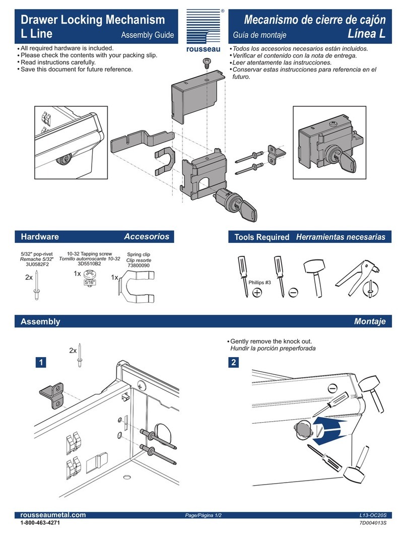
Simon ZVE-UNI I User manual

BA_ZVE-UNI_DE-EN_21 www.simon-protec.com Datum/Date: 19.04.2018
Ausgabe/Issue: 2.1/03.2018 [email protected]om
ZVE-UNI A / ZVE-UNI I 2.1/03.2018
Seite/Page 1
Betriebsanleitung / Operating Manual
Elektrische Zusatzverriegelung ZVE-UNI
Supplementary Electric Locking ZVE-UNI
Nur gültig in Verbindung mit dem Beiblatt: Sicherheitshinweise & Gewährleistungsbedingungen!
Only valid in combination with the attached sheet “safety instructions and warranty conditions”!
BA_ZVE-UNI_DE-EN_21
Copyright by SIMON PROtec Systems GmbH
Vorbehaltlich technischer Änderungen und Irrtümer.
Subject to technical changes and errors.
Abbildungen exemplarisch! / Pictures exemplary!
ZVE-UNI A
ZVE-UNI I
Leitungseinführung –
Ansicht von unten (Ausschnitt)
Cable inlet –
view from below (detail)
Konsolensatz nach außen öffnend
bracket set outward opening
K-ZVE-UNI-MP-A
Konsolensatz nach innen öffnend
bracket set inward opening
K-ZVE-UNI-MP-I
ZVE-UNI A
Montage-Video:
Nach innen
öffnendes
Fenster.
Mounting-Video:
inward opening
window

Betriebsanleitung / Operating Manual
Elektrische Zusatzverriegelung ZVE-UNI
Supplementary Electric Locking ZVE-UNI
BA_ZVE-UNI_DE-EN_21 Datum/Date: 19.04.2018
Ausgabe/Issue: 2.1/03.2018
Inhaltsverzeichnis
Seite/Page 2
1. Allgemein ...........................................................................................................................................................4
1.1 Vorwort zu dieser Anleitung ..........................................................................................................................4
1.2 Bestimmungsgemäßer Gebrauch .................................................................................................................5
1.3 Produktbeschreibung ....................................................................................................................................5
1.3.1 Auslieferungszustand ................................................................................................................................5
2. Inbetriebnahme – Montage-Reihenfolge .......................................................................................................5
2.1 Zusatzverriegelung ........................................................................................................................................5
2.2 Abrollblock .....................................................................................................................................................6
2.3 Probebetrieb ..................................................................................................................................................7
3. Montage .............................................................................................................................................................8
3.1 ZVE-UNI A – nach innen öffnend ..................................................................................................................8
3.2 ZVE-UNI A – nach außen öffnend ................................................................................................................9
3.3 ZVE-UNI I – nach innen öffnend .................................................................................................................10
3.4 Montage-Hilfe ..............................................................................................................................................11
3.5 Abrollblock und Befestigungsblock .............................................................................................................11
3.6 Elektrischer Anschluss ................................................................................................................................13
3.6.1 Eine Verriegelung und ein Antrieb mit F-Kontakt .........................................................................................14
3.6.2 Eine Verriegelung und zwei Antriebe mit F-Kontakt .....................................................................................14
3.6.3 Eine Verriegelung und ein Antrieb mit potentialfreien Kontakt ......................................................................15
3.6.4 Eine Verriegelung und zwei Antriebe mit potentialfreien Kontakt ..................................................................16
3.6.5 Zwei Verriegelungen und ein Antrieb .........................................................................................................16
3.6.6 Eine Verriegelung, Abfolgeregler und ein Antrieb ........................................................................................17
3.6.7 Testlauf ohne Öffneraggregat ...................................................................................................................18
3.7 Leitungsanschluss .......................................................................................................................................19
4. Technische Daten ...........................................................................................................................................20
5. Pflege und Wartung ........................................................................................................................................23
6. Sicherheitsbestimmungen .............................................................................................................................23
7. Anhang .............................................................................................................................................................23
7.1 Allgemeine Geschäfts- und Lieferbedingungen ..........................................................................................23
7.2 Herstellererklärung ......................................................................................................................................23
7.3 EG-Herstellererklärung (Inverkehrbringer) ..................................................................................................23
7.4 Firmenanschriften .......................................................................................................................................24

BA_ZVE-UNI_DE-EN_21 Datum/Date: 19.04.2018
Ausgabe/Issue: 2.1/03.2018
Table of Contents
Betriebsanleitung / Operating Manual
Elektrische Zusatzverriegelung ZVE-UNI
Supplementary Electric Locking ZVE-UNI
Seite/Page 3
1. Preface ............................................................................................................................................................... 4
1.1 Foreword to this manual ............................................................................................................................... 4
1.2 Use for the intended purpose ........................................................................................................................ 5
1.3 Product description ....................................................................................................................................... 5
1.3.1 Delivery status .......................................................................................................................................... 5
2. Commissioning – Mounting sequence ........................................................................................................... 5
2.1 Locking device .............................................................................................................................................. 5
2.2 Roll-off block ................................................................................................................................................ 6
2.3 Test run ........................................................................................................................................................ 7
3. Installation .......................................................................................................................................................... 8
3.1 ZVE-UNI A – inward opening ........................................................................................................................ 8
3.2 ZVE-UNI A – outward opening ..................................................................................................................... 9
3.3 ZVE-UNI I – inward opening ...................................................................................................................... 10
3.4 Assembling aid ........................................................................................................................................... 11
3.5 Roll-off block and mounting block .............................................................................................................. 11
3.6 Electrical connection .................................................................................................................................. 13
3.6.1 One locking and one actuator with F-contact .............................................................................................. 14
3.6.2 One locking and two actuators with F-contact ............................................................................................ 14
3.6.3 One locking and one actuator with potential-free contact ............................................................................. 15
3.6.4 One locking and two actuators with potential-free contact ............................................................................ 16
3.6.5 Two lockings and one actuator ................................................................................................................. 16
3.6.6 One locking, sequence controller and one actuator ..................................................................................... 17
3.6.7 Test run without opening actuator ............................................................................................................. 18
3.7 Cable connection ....................................................................................................................................... 19
4. Technical data ................................................................................................................................................. 20
5. Care and maintenance ................................................................................................................................... 23
6. Safety regulations ........................................................................................................................................... 23
7. Appendix .......................................................................................................................................................... 23
7.1 General conditions of business and terms of delivery ................................................................................ 23
7.2 Manufacturer’s declaration .......................................................................................................................... 23
7.3 EC manufacturer’s declaration (distributor) ................................................................................................ 23
7.4 Company addresses ................................................................................................................................... 24

Betriebsanleitung / Operating Manual
Elektrische Zusatzverriegelung ZVE-UNI
Supplementary Electric Locking ZVE-UNI
Allgemein / Preface
BA_ZVE-UNI_DE-EN_21 Datum/Date: 19.04.2018
Ausgabe/Issue: 2.1/03.2018
Seite/Page 4
BA_ZVE-UNI_DE-EN_21
1. Allgemein
1.1 Vorwort zu dieser Anleitung
Diese Anleitung ist für die fachgerechte Bedienung, Installati-
on und Wartung durch geschultes, sachkundiges Fachperso-
nal (wie z.B. Mechatroniker oder Elektroinstallateur) und/
oder Fachpersonal mit Kenntnissen in der elektrischen Gerä-
teinstallation ausgelegt.
Lesen Sie diese Betriebsanleitung aufmerksam durch und
beachten Sie insbesondere die Gefahrenhinweise. Bewahren
Sie diese Betriebsanleitung für späteren Gebrauch/Wartung
auf. Bitte beachten Sie genau die Anschlussbelegung, die mi-
nimalen und maximalen Leistungsdaten (siehe „Technische
Daten”) und die Installationshinweise. Die unkorrekte Ver-
wendung oder nicht fachgerechte Bedienung/Montage kön-
nen den Verlust der Systemfunktionen verursachen und
Schäden an Sachen und/oder Personen hervorrufen.
Folgende Symbole finden Sie in dieser Anleitung:
So sind Handlungsanweisungen gekennzeichnet.
Folgerungen werden so dargestellt.
•Taster oder Schalter die betätigt werden sollen, werden
fett dargestellt.
• „Anzeigen“ werden in Anführungszeichen gesetzt.
1. Preface
1.1 Foreword to this manual
This manual has been created for the purposes of proper op-
eration, installation and maintenance by trained, experienced
specialist personnel (e.g. mechatronics engineer or electri-
cian) and/or specialist personnel with knowledge involving
the installation of electrical devices.
Read the operating manual carefully and observe in particular
the caution and danger hints. Retain the operating manual for
later use/maintenance. Please precisely observe the pin as-
signment, the minimum and maximum performance data (see
“Technical data”) and the installation instructions. Incorrect
usage or improper operation/assembly can cause the loss of
system functions and result in damage to property and/or
persons.
You will find the following symbols in this manual:
This is how operating procedures are identified.
Consequences are represented this way.
•Buttons or switches to be activated are indicated bold-
face.
• “Displays” are placed in quotation marks.
INFORMATION
Eine Information gibt Ihnen zusätzliche Tipps!
ACHTUNG
Ein Warnhinweis macht Sie auf mögliche Gefahren für das
Produkt aufmerksam.
GEFAHR
Ein Warnhinweis macht Sie auf mögliche Gefahren für Ihr
Leben oder Ihre Gesundheit aufmerksam!
UMWELTHINWEIS
Ein Warnhinweis macht Sie auf mögliche Gefahren für die
Umwelt aufmerksam!
INFORMATION
This information provides you with additional tips!
CAUTION
This warning draws your attention to potential dangers for
the product!
DANGER
This warning draws your attention to possible risks to your
life or health!
ENVIRONMENTAL NOTE
This warning draws your attention to potential dangers for
the environment!

BA_ZVE-UNI_DE-EN_21 Datum/Date: 19.04.2018
Ausgabe/Issue: 2.1/03.2018
Inbetriebnahme – Montage-Reihenfolge / Commissioning – Mounting sequence
Seite/Page 5
Betriebsanleitung / Operating Manual
Elektrische Zusatzverriegelung ZVE-UNI
Supplementary Electric Locking ZVE-UNI
1.2 Bestimmungsgemäßer Gebrauch
Verriegelungsaggregate (Verriegelungen) dienen zur zusätz-
lichen Sicherung/Verriegelung von Fenstern, welche zur Lüf-
tung von Räumen oder zur Ableitung von Brandrauch
verwendet werden können.
Die Verriegelung und die angesteuerten Antriebe müssen ge-
mäß der durchzuführenden Risikobeurteilung um eventuelle
Schutzmaßnahmen erweitert werden.
1.3 Produktbeschreibung
Diese Verriegelung ist für die Montage an Fenstern (Blen-
drahmen, sowie mitlaufend am Fensterflügel) geeignet. Sie
ist einsetzbar mit RWA- und/oder Lüftungssteuerungen. Die
Verriegelung eignet sich zum Einbau und für die Funktion in
Rauchabzügen.
Die elektrische Zusatzverriegelung ermöglicht die Erhöhung
des Anpressdruckes bei hohen und breiten Fensterflügeln
und sorgt für eine mechanische Verriegelung.
Sie ist universell einsetzbar, sowohl an nach innen oder nach
außen öffnenden Fenstern, als auch an DIN Links oder DIN
Rechts Fenstern.
Der Verriegelungsbeschlag ZVE-UNI wird in zwei Installa-
tionsvarianten mit außenliegender Verkabelung (ZVE-UNI A)
und im Fenster integrierter Verkabelung (ZVE-UNI I) angebo-
ten.
Verwendet wird die Verriegelung in Verbindung mit elektro-
mechanischen Antrieben, wobei die ZVE-UNI die Folgerege-
lung der angeschlossenen Antriebe übernimmt.
1.3.1 Auslieferungszustand
Die ZVE-UNI A/I wird mit integrierten Montagehilfen (Schrau-
benführung) ausgeliefert, in diesen sind bereits je zwei selbst-
bohrende Schrauben für Aluminiumprofile integriert (siehe
Kapitel 3.4 auf Seite 11).
1.2 Use for the intended purpose
Interlocking actuators (lockings) serve for the additional
securing/locking of windows, which can be installed in walls
or in roofs and used for the ventilation of rooms or for the ex-
haust of smoke.
The locking and the connected actuators may have to be ex-
tended by protective measures in accordance with the risk as-
sessment which is to be carried out.
1.3 Product description
This locking is suitable for mounting on windows (blind frames
as well as along the window leaf). It can be used with SHE
and/or ventilation controls. The locking is suitable for installa-
tion and for the operation in smoke extractions.
The supplementary electric locking system allows an in-
crease in the contact pressure with high and wide window
wings and ensures a mechanical locking.
It is universally applicable, both inward or outward opening
windows, as well as to DIN left or DIN right windows.
The locking ZVE-UNI is offered in two installation variants
with external wiring (ZVE-UNI A) and in the window of inte-
grated wiring (ZVE-UNI I).
The locking is used in combination with electromechanical ac-
tuators, the ZVE-UNI takes over the sequence control of the
connected actuators.
1.3.1 Delivery status
The ZVE-UNI A/I is delivered with integrated mounting aids
(screw guide), in each are two self-drilling screws for alumin-
ium profiles already integrated (see chapter 3.4 on page 11).
2. Inbetriebnahme – Montage-Reihenfolge
2.1 Zusatzverriegelung
Montageposition und Ausführung am Fenster festlegen.
Montageposition: Die Zusatzverriegelung sollte mit dem
Verriegelungsschlitten an der Mitte der Hauptschließ-
kante oder bei der Verwendung von zwei Zusatzverriege-
lungen im Verhältnis 1/4 : 1/2 : 1/4 positioniert werden.
INFORMATION
Wir empfehlen die Montageposition am Fenster anhand
einer Schnittzeichnung zu überprüfen, um die idealen
Befestigungspunkte zu ermitteln. Hierbei unterstützt
Sie gerne unser technischer Vertrieb.
2. Commissioning – Mounting sequence
2.1 Locking device
Determinate mounting position and mounting variant on
the window.
Mounting position: The supplementary locking should
be positioned with the locking slide at the centre of the
main closing edge or when using two additional locks in
the ratio 1/4 : 1/2 : 1/4.
INFORMATION
We recommend that you check the mounting position
on the window by an intersection drawing to deter-
mine the ideal mounting points. Our technical sales
department will be glad to assist you.

Betriebsanleitung / Operating Manual
Elektrische Zusatzverriegelung ZVE-UNI
Supplementary Electric Locking ZVE-UNI
Inbetriebnahme – Montage-Reihenfolge / Commissioning – Mounting sequence
BA_ZVE-UNI_DE-EN_21 Datum/Date: 19.04.2018
Ausgabe/Issue: 2.1/03.2018
Seite/Page 6
Ausführung: Nach innen öffnende Fenster optional mit
Befestigungsplatte (Artikel K-ZVE-UNI-MP-I, siehe
Kapitel 3.1 auf Seite 8). Nach außen öffnende Fenster
mit Konsolensatz „nach außen öffnend“ (Artikel K-ZVE-
UNI-MP-A, siehe Kapitel 3.2 auf Seite 9).
Für die Installationsvariante I (innenliegende Verkabe-
lung) fertigen Sie eine Öffnung am Rahmen an (siehe
Abbildung 3: „ZVE-UNI I – nach innen öffnend“ auf
Seite 10).
Markieren Sie die Bohrpositionen für die Zusatzverriege-
lung und fertigen Sie ggf. je nach Material des Fensters
und Wahl der Befestigungsmittel entsprechende Bohrun-
gen an. Alternative Befestigungsmittel sind nicht im Liefe-
rumfang enthalten.
Für die Installationsvariante I (innenliegende Verkabe-
lung) ziehen sie die Anschlussleitungen durch das Profil
und schließen Sie die Zusatzverriegelung an (siehe
Kapitel 3.6 „Elektrischer Anschluss“ auf Seite 13).
Montieren Sie die Verriegelung an der zuvor festgelegten
Position (siehe Kapitel 3.1 „ZVE-UNI A – nach innen öff-
nend“ auf Seite 8, Kapitel 3.2 „ZVE-UNI A – nach außen
öffnend“ auf Seite 9 bzw. Kapitel 3.3 „ZVE-UNI I – nach
innen öffnend“ auf Seite 10).
Für die Installationsvariante A (außenliegende Verkabe-
lung) erfolgt der elektrische Anschluss nach der Montage
der Verriegelung (siehe Kapitel 3.6 „Elektrischer
Anschluss“ auf Seite 13).
Mounting variant: Inward opening windows optional
with mounting plate article K-ZVE-UNI-MP-I, see
chapter 3.1 on page 8). Outward opening windows with
console set “outward opening” (article K-ZVE-UNI-MP-A,
see chapter 3.2 on page 9).
For installation variant I (internal wiring), make an open-
ing on the frame (see Figure 3: “ZVE-UNI I – inward
opening” on page 10).
Mark the drill positions for the supplementary locking
and, if necessary, make appropriate holes, depending on
the material of the window and the choice of fastenings.
Alternative fastenings are not included in state of deliv-
ery.
For installation variant I (internal wiring), lay the connec-
tion cables through the profile and connect the supple-
mentary electric locking (see chapter 3.6 “Electrical
connection” on page 13).
Mount the locking at the pre-determined position (see
chapter 3.1 “ZVE-UNI A – inward opening” on page 8,
chapter 3.2 “ZVE-UNI A – outward opening” on page 9
respectively chapter 3.3 “ZVE-UNI I – inward opening” on
page 10).
For the installation variant A (external wiring), the electri-
cal connection takes place after mounting the locking
(see chapter 3.6 “Electrical connection” on page 13).
2.2 Abrollblock
Montieren Sie den Abrollblock am Befestigungsblock
(siehe Abbildung 5 auf Seite 12) und den Zylinderstift im
Verriegelungsschlitten der Zusatzverriegelung, so dass
Zylinderstift beim Verriegelungsvorgang auf die schräge
Fläche des Abrollblocks trifft.
2.2 Roll-off block
Mount the roll-off block on the mounting block (see
Figure 5 on page 12) and the cylinder pin in the locking
slide of the locking so that the cylinder pin meets the
inclined surface of the roll-off block during the locking
process.
INFORMATION
Bei der Montage an nach innen öffnenden Aluminium-
Profilen können Sie die ZVE-UNI direkt mit den bereits
in der Montagehilfe eingesetzten selbstbohrenden
Schrauben befestigen.
INFORMATION
Mit Hilfe der beiden mitgelieferten Klebepads können
Sie die ZVE-UNI kurzzeitig auf der Montageposition am
Fenster fixieren.
INFORMATION
When mounting on inward-opening aluminium pro-
files, you can attach the ZVE-UNI directly with the self-
drilling screws already inserted in the assembly aid.
INFORMATION
With the aid of the two provided adhesive pads, you
can fix the ZVE-UNI to the window for a short time.
Abroll- und Befestigungsblock Zylinderstift im Verriegelungsschlitten

BA_ZVE-UNI_DE-EN_21 Datum/Date: 19.04.2018
Ausgabe/Issue: 2.1/03.2018
Inbetriebnahme – Montage-Reihenfolge / Commissioning – Mounting sequence
Seite/Page 7
Betriebsanleitung / Operating Manual
Elektrische Zusatzverriegelung ZVE-UNI
Supplementary Electric Locking ZVE-UNI
Markieren Sie die Bohrpostionen des Befestigungs-
blocks. Zwischen Verriegelungsschlitten und Abrollblock
sollte ein Abstand von 1 mm und maximal 4 mm einge-
halten werden. Beachten Sie die hierbei die Breite des
Fensterprofils bei nach außen öffnenden Fenstern, so
dass der Abrollblock nicht mit dem Rahmen kollidiert
(siehe Abbildung 5 auf Seite 12).
Montieren Sie den Befestigungsblock an der zuvor fest-
gelegten Position (siehe Kapitel 3.5 „Abrollblock und
Befestigungsblock“ auf Seite 11).
Mark the drill posts of the mounting block. A distance of
1 mm to a maximum of 4 mm should be maintained
between the locking slide and the roll-off block. When the
windows are opening outwards consider the width of the
window profile, so that the roll-off block does not collide
with the frame (see Figure 5 on page 12).
Mount the mounting block at the pre-determined position
(see chapter 3.5 “Roll-off block and mounting block” on
page 11).
2.3 Probebetrieb
Zum Probebetrieb, um die ZVE-UNI wieder zu schließen, ist
ein F-Kontakt vom Antrieb notwendig (siehe Kapitel 3.6.7
„Testlauf ohne Öffneraggregat“ auf Seite 18).
Alternativ können Sie das Öffneraggregat elektrisch mit dem
Verriegelungsantrieb verbinden, jedoch noch nicht am Fens-
ter installieren.
Führen Sie einen Probetrieb durch.
Erster Durchlauf: Setzen Sie den Zylinderstift noch
nicht in den Verriegelungsschlitten ein, so können Sie
per Hand die Montageposition des Abrollblocks noch im
nicht montierten Zustand überprüfen.
Zweiter Durchlauf: Nach der Einsetzen des Zylin-
derstifts im Verriegelungsschlitten und Montage des
Abrollblocks führen Sie eine weitere Testfahrt durch
(siehe Kapitel 3.6.7 auf Seite 18).
INFORMATION
Ist der Zylinderstift erst einmal in den Verriegelungs-
schlitten eingesetzt, so lässt er sich nur noch schwer
wieder entfernen.
Dritter Durchlauf: Nach dem Anschluss der Öffnerag-
gregate einen abschließenden Testlauf durchführen.
2.3 Test run
For the test run, an F-contact from the opening actuator is
necessary to close the ZVE-UNI (see chapter 3.6.7 “Test run
without opening actuator” on page 18).
Alternatively, you can electrically connect the opening actua-
tor to the locking but do not yet install the actuator on the win-
dow.
Carry out a test run.
First run: Do not insert the cylinder pin yet into the lock-
ing slide, so you can manually check the assembly posi-
tion of the roll-off block in the unmounted state.
Second run: After inserting the cylinder pin in the locking
slide and installing the roll-off block, perform another test
run (see chapter 3.6.7 on page 18).
Third run: After connecting the opening actuators, per-
form a final test run.
INFORMATION
Vor der endgültigen Montage des Abrollblocks empfeh-
len wir eine Testfahrt der Zusatzverrieglung (ohne Zy-
linderstift) um die Montageposition des Befestigungs-
blocks zu kontrollieren.
INFORMATION
Before the final mounting of the roll-off block, we rec-
ommend a test drive of the supplementary locking
(without cylinder pin) to check the mounting position of
the mounting block.
INFORMATION
Wir empfehlen einen Probebetrieb mit einer geeigneten
mobilen Energieversorgung (inkl. Steuereinrichtung, kein
Akku alleine) durchzuführen. Dadurch kann einfach und
schnell auf Fehlfunktionen reagiert werden.
+
+
24V
INFORMATION
We recommend that a test run be carried out using a ap-
propriate mobile power supply (including control unit, no
battery alone). This allows simple and fast reaction to
malfunctions.
INFORMATION
Once the cylinder pin is inserted into the locking slide,
it is difficult to remove it.
+
+
24V

Betriebsanleitung / Operating Manual
Elektrische Zusatzverriegelung ZVE-UNI
Supplementary Electric Locking ZVE-UNI
Montage / Installation
BA_ZVE-UNI_DE-EN_21 Datum/Date: 19.04.2018
Ausgabe/Issue: 2.1/03.2018
Seite/Page 8
3. Montage
3.1 ZVE-UNI A – nach innen öffnend
Legen Sie die Montageposition der Zusatzverriegelung
fest und markieren Sie gegebenenfalls die Befestigungs-
punkte. Für Kunststofffenster und bei erschwerten Befes-
tigungsbedingungen steht der optionale Konsolensatz
K-ZVE-UNI-MP-I (siehe unten) zur Verführung.
Je nach Material und Bauweise des Fensters wählen Sie
passende Befestigungsmittel aus.
Für viele Aluminium-Fenster eignen sich die mitgeliefer-
ten selbstbohrenden Schrauben (siehe Kapitel 3.4 „Mon-
tage-Hilfe“ auf Seite 11).
Mit Hilfe der mitgelieferten Klebepunkte können Sie den
Antrieb kurzzeitig auf der Befestigungsposition fixieren
und die Verriegelung mit dem Fenster verschrauben.
Siehe Kapitel 3.6 „Elektrischer Anschluss“ auf Seite 13.
3. Installation
3.1 ZVE-UNI A – inward opening
Determine the mounting position of the supplementary
locking and, if necessary, mark the mounting points. For
plastic windows and difficult mounting conditions, the
optional bracket set K-ZVE-UNI-MP-I (see below) is
available.
Depending on the material and construction of the win-
dow, select suitable fastenings.
The supplied self-drilling screws are suitable for many
aluminium windows (see chapter 3.4 “Assembling aid” on
page 11).
With the aid of the two provided adhesive pads, you can
fix the ZVE-UNI to the window for a short time and screw
the locking to the window.
See chapter 3.6 “Electrical connection” on page 13.
Abbildung 1: ZVE-UNI A – nach innen öffnend Figure 1: ZVE-UNI A – inward opening
Position des Zylinderstifts je nach
Überstand Fenster/Rahmen wählen.
Select the position of the cylinder pin
according to the window/frame overhang.
Konsolensatz nach innen öffnend (optional)
bracket set inward opening (optional)
K-ZVE-UNI-MP-I

BA_ZVE-UNI_DE-EN_21 Datum/Date: 19.04.2018
Ausgabe/Issue: 2.1/03.2018
Montage / Installation
Seite/Page 9
Betriebsanleitung / Operating Manual
Elektrische Zusatzverriegelung ZVE-UNI
Supplementary Electric Locking ZVE-UNI
3.2 ZVE-UNI A – nach außen öffnend
Mit den beiden Vierkantmuttern und zugehörigen Senk-
kopfschrauben verschrauben Sie die Befestigungsleiste
mit der Zusatzverriegelung (Konsole K-ZVE-UNI-MP-A
muss separat bestellt werden).
Legen Sie die Montageposition der Zusatzverriegelung
fest und markieren Sie die Befestigungspunkte.
Je nach Material und Bauweise des Fensters wählen Sie
geeignete Befestigungsmittel aus.
Mit Hilfe der mitgelieferten Klebepunkte können Sie den
Antrieb kurzzeitig auf der Befestigungsposition fixieren
und die Verriegelung mit dem Fenster verschrauben.
Siehe Kapitel 3.6 „Elektrischer Anschluss“ auf Seite 13.
3.2 ZVE-UNI A – outward opening
Fix the mounting bar onto the supplementary locking with
the two square nuts and the corresponding countersunk
screws (bracket K-ZVE-UNI-MP-A must be ordered sep-
arately).
Determine the mounting position of the supplementary
locking and mark the mounting points.
Depending on the material and construction of the win-
dow, select suitable fastenings.
With the aid of the two provided adhesive pads, you can
fix the ZVE-UNI to the window for a short time and screw
the locking to the window.
See chapter 3.6 “Electrical connection” on page 13.
Abbildung 2: ZVE-UNI A – nach außen öffnend Figure 2: ZVE-UNI A – outward opening
Position des Zylinderstifts je nach
Überstand Fenster/Rahmen wählen.
Select the position of the cylinder pin
according to the window/frame overhang.
Befestigungsleiste
mounting bar
K-ZVE-UNI-MP-A

Betriebsanleitung / Operating Manual
Elektrische Zusatzverriegelung ZVE-UNI
Supplementary Electric Locking ZVE-UNI
Montage / Installation
BA_ZVE-UNI_DE-EN_21 Datum/Date: 19.04.2018
Ausgabe/Issue: 2.1/03.2018
Seite/Page 10
3.3 ZVE-UNI I – nach innen öffnend
Legen Sie die Montageposition der Zusatzverriegelung
fest. Für Kunststofffenster und bei erschwerten Befesti-
gungsbedingungen steht der optionale Konsolensatz
K-ZVE-UNI-MP-I (siehe Seite 8) zur Verführung.
Markieren Sie die Befestigungspunkte.
Markieren Sie die 20 mm×20 mm Aussparung am Fens-
ter.
Fertigen Sie die 20 mm×20 mm Aussparung an.
Schließen Sie die Zusatzverriegelung ZVE-UNI elektrisch
an (siehe Kapitel 3.6 auf Seite 13).
Je nach Material und Bauweise des Fensters wählen Sie
geeignete Befestigungsmittel aus.
Für viele Aluminium-Fenster eignen sich die mitgeliefer-
ten selbstbohrenden Schrauben (siehe Kapitel 3.4 „Mon-
tage-Hilfe“ auf Seite 11).
Mit Hilfe der mitgelieferten Klebepunkte können Sie den
Antrieb kurzzeitig auf der Befestigungsposition fixieren
und die Verriegelung mit dem Fenster verschrauben.
3.3 ZVE-UNI I – inward opening
Determine the mounting position of the supplementary
locking. For plastic windows and difficult mounting condi-
tions, the optional bracket set K-ZVE-UNI-MP-I (see
page 8) is available.
Mark the fastening points.
Mark the 20 mm×20 mm opening on the window.
Make the 20 mm×20 mm opening.
Connect the supplementary locking ZVE-UNI electrically
(see chapter 3.6 on page 13).
Depending on the material and construction of the win-
dow, select suitable fastenings.
The supplied self-drilling screws are suitable for many
aluminium windows (see chapter 3.4 “Assembling aid” on
page 11).
With the aid of the two provided adhesive pads, you can
fix the ZVE-UNI to the window for a short time and screw
the locking to the window.
Abbildung 3: ZVE-UNI I – nach innen öffnend Figure 3: ZVE-UNI I – inward opening
Position des Zylinderstifts je nach
Überstand Fenster/Rahmen wählen.
Leitungseinführung –
Ansicht von unten (Ausschnitt)
Cable inlet –
view from below (detail)
Select the position of the cylinder pin
according to the window/frame overhang.

BA_ZVE-UNI_DE-EN_21 Datum/Date: 19.04.2018
Ausgabe/Issue: 2.1/03.2018
Montage / Installation
Seite/Page 11
Betriebsanleitung / Operating Manual
Elektrische Zusatzverriegelung ZVE-UNI
Supplementary Electric Locking ZVE-UNI
3.4 Montage-Hilfe
Für die mitgelieferten selbstbohrenden Linsenkopfschrauben
oder Schrauben ähnlichen Formates steht eine Montagehilfe
für die Ausrichtung der Schrauben oberhalb der Bohrungen
im Antrieb zur Verfügung.
Die ZVE-UNI wird bereits mit integrierten Montagehilfen und
Schrauben ausgeliefert, diese müsse je nach Montageaus-
richtung ggf. um 180° gedreht werden.
Wenn Sie andere Schrauben, als die mitgelieferten ver-
wenden, dann setzen Sie jeweils ein Schraubenpaar in
die Montagehilfe ein.
Positionieren Sie das Schraubenpaar oberhalb der Boh-
rungen im inneren der ZVE-UNI.
Verschrauben Sie die ZVE-UNI mit dem Fenster durch
die Montagehilfe hindurch.
3.4 Assembling aid
For the supplied self-drilling lens head screws or similar for-
mat an assembly aid is provided for the alignment of the
screws above the holes inside the actuator.
The ZVE-UNI is already supplied with integrated mounting
aids and screws, which may have to be rotated through 180°
depending on the mounting orientation.
If you use other screws than the supplied, then insert a
pair of screws into the mounting aid.
Position the screw pair above the holes inside the sup-
plementary locking ZVE-UNI.
Screw the ZVE-UNI with the window through the mount-
ing aid.
Abbildung 4 Figure 4
3.5 Abrollblock und Befestigungsblock
Montieren Sie den Abrollblock am Befestigungsblock und
den Zylinderstift im Verriegelungsschlitten der Zusatzver-
riegelung, so dass Zylinderstift beim Verriegelungsvor-
gang auf die schräge Fläche des Abrollblocks trifft.
Markieren Sie die Bohrpositionen des Befestigungs-
blocks. Zwischen Verriegelungsschlitten und Abrollblock
sollte ein Abstand von min. 1 mm bis max. 4 mm einge-
halten werden.
3.5 Roll-off block and mounting block
Mount the roll-off block on the mounting block and the
cylinder pin in the locking slide of the locking, so that the
cylinder pin meets the inclined surface of the roll-off block
during the locking process.
Mark the drilling positions of the mounting block. A dis-
tance of at least 1 mm up to a maximum of 4 mm should
be maintained between the locking slide and the roll-off
block.
INFORMATION
Vor der endgültigen Befestigung des Montageblocks
mit dem Abrollblock empfehlen wir eine Testfahrt der
Zusatzverrieglung (ohne Zylinderstift) auszuführen um
die Position des Befestigungsblocks zu kontrollieren
(siehe Kapitel 2.3 „Probebetrieb“ auf Seite 7).
INFORMATION
Before the final assembly of the mounting block with
roll-off block, we recommend a test drive of the lock-
ing (without cylinder pin) to check the mounting posi-
tion of the fastening block (see chapter 2.3 “Test run”
on page 7).

Betriebsanleitung / Operating Manual
Elektrische Zusatzverriegelung ZVE-UNI
Supplementary Electric Locking ZVE-UNI
Montage / Installation
BA_ZVE-UNI_DE-EN_21 Datum/Date: 19.04.2018
Ausgabe/Issue: 2.1/03.2018
Seite/Page 12
Montieren Sie den Befestigungsblock mit Abrollblock an der zuvor festgelegten Position.
Mount the mounting block with roll-off block at the pre-determined position.
Abbildung 5
Figure 5

BA_ZVE-UNI_DE-EN_21 Datum/Date: 19.04.2018
Ausgabe/Issue: 2.1/03.2018
Montage / Installation
Seite/Page 13
Betriebsanleitung / Operating Manual
Elektrische Zusatzverriegelung ZVE-UNI
Supplementary Electric Locking ZVE-UNI
3.6 Elektrischer Anschluss 3.6 Electrical connection
GEFAHR
Die Montage darf nur von fachkundigem
Personal (Elektrofachkraft) durchgeführt
werden. Für die Montage, Installation und
Inbetriebnahme gelten alle national relevan-
ten Sicherheitsbestimmungen und Vor-
schriften.
Bei nicht sachgemäßer Montage besteht die
Gefahr eines elektrischen Schlages. Halten
Sie unbedingt die gültigen Sicherheitsregeln
ein. Beachten Sie die gültigen Montagevor-
schriften. Falsche Montage kann zu ernst-
haften Verletzungen führen.
GEFAHR
Erst nach Überprüfung der gesamten Anlage an die Ener-
gieversorgung (24 VDC) anschließen.
ACHTUNG
Stellen Sie sicher, dass die Schlaufen der Versorgungslei-
tung, unter Berücksichtigung der Biegeradien, an bewegli-
chen Teilen ausreichend dimensioniert sind, um ein Ein-
klemmen oder Abreißen der Anschlussleitung zu verhin-
dern.
ACHTUNG
Elektrischen Anschluss nicht erden.
Der Antrieb darf nur mit 24 VDC Schutzkleinspannung be-
trieben werden.
Alle nicht verwendeten Adern elektrisch isolieren.
DANGER
Assembly must be carried out by specialist
personnel only (qualified electricians). All
relevant national safety regulations and di-
rectives apply to assembly, installation and
start-up.
Incorrect assembly can result in electric
shock. All safety regulations must be com-
plied with. Follow the current assembly in-
structions. Faulty assembly can result in
serious injuries.
DANGER
Check the complete system before connecting to the
power supply (24 VDC).
CAUTION
To avoid damages of actuators connection cable during
movement of window ensure cable loops with sufficient
distance to all moving parts.
CAUTION
Do not earth the electrical connection.
The actuator may only be run with 24 VDC protective low
voltage!
Insulate all unused wires.

Betriebsanleitung / Operating Manual
Elektrische Zusatzverriegelung ZVE-UNI
Supplementary Electric Locking ZVE-UNI
Montage / Installation
BA_ZVE-UNI_DE-EN_21 Datum/Date: 19.04.2018
Ausgabe/Issue: 2.1/03.2018
Seite/Page 14
3.6.1 Eine Verriegelung und ein Antrieb mit F-Kontakt
Leitungen gemäß Anschlussplan verbinden (die Aderfar-
ben sind nur gültig für kompatible Antriebe mit werkssei-
tig montierterAnschlussleitung).
3.6.1 One locking and one actuator with F-contact
Connect the wires according to the wiring diagram (the
wire colours are only valid for compatible actuators with a
connection cable installed at the factory).
3.6.2 Eine Verriegelung und zwei Antriebe mit F-Kontakt
Leitungen gemäß Anschlussplan verbinden (die Aderfar-
ben sind nur gültig für kompatible Antriebe mit werkssei-
tig montierterAnschlussleitung).
3.6.2 One locking and two actuators with F-contact
Connect the wires according to the wiring diagram (the
wire colours are only valid for compatible actuators with a
connection cable installed at the factory).
24 V DC
Steuerung
control unit
SO
Antrieb / actuator
ZVE-UNI
blau / blue
weiß / white
schwarz / black
grau / grey
braun / brown
grün / green
blau / blue
schwarz / black
braun / brown
F-Kontakt: Nicht an „G“ der Steuerung anklemmen!
“F”-Contact: Do not connect with “G” on the control unit!
ZU
CLOSE
(-) (+)
AUF
OPEN -
+
SFO
ACHTUNG / ATTENTION
Die maximale Stromaufnahme aller angeschlossenen An-
triebe darf zusammen 6 A nicht überschreiten.
The maximum current consumption of all connected actu-
ators must not exceed 6 A at all.
24 V DC
Steuerung
control unit
SO
1. Antrieb / 1. actuator
ZVE-UNI
blau / blue
weiß / white
schwarz / black
grau / grey
braun / brown
grün / green
blau / blue
schwarz / black
braun / brown
F-Kontakt: Nicht an „G“ der Steuerung anklemmen!
“F”-Contact: Do not connect with “G” on the control unit!
ZU
CLOSE
(-) (+)
AUF
OPEN -
+
SFO
2. Antrieb / 2. actuator
SFO
G T G T
gelb / yellow
rot / red
ACHTUNG / ATTENTION
Die maximale Stromaufnahme aller angeschlossenen An-
triebe darf zusammen 6 A nicht überschreiten.
The maximum current consumption of all connected actu-
ators must not exceed 6 A at all.

BA_ZVE-UNI_DE-EN_21 Datum/Date: 19.04.2018
Ausgabe/Issue: 2.1/03.2018
Montage / Installation
Seite/Page 15
Betriebsanleitung / Operating Manual
Elektrische Zusatzverriegelung ZVE-UNI
Supplementary Electric Locking ZVE-UNI
3.6.3 Eine Verriegelung und ein Antrieb mit
potentialfreien Kontakt
Leitungen gemäß Anschlussplan verbinden (die Aderfar-
ben sind nur gültig für kompatible Antriebe mit werkssei-
tig montierterAnschlussleitung). Der potentialfreie
Kontakt des Antriebs muss in „ZU“ aktiviert sein!
3.6.3 One locking and one actuator with potential-free
contact
Connect the wires according to the wiring diagram (the
wire colours are only valid for compatible actuators with a
connection cable installed at the factory). The potential-
free contact of the actuator must be activated in
“CLOSE”.
24 V DC
Steuerung
control unit
SO
Antrieb / actuator
ZVE-UNI
blau / blue
weiß / white
schwarz / black
grau / grey
braun / brown
grün / green
blau / blue
schwarz / black
braun / brown
F-Kontakt: Nicht an „G“ der Steuerung anklemmen!
“F”-Contact: Do not connect with “G” on the control unit!
ZU
CLOSE
(-) (+)
AUF
OPEN -
+
SOG
NO2NO1 T
grau / grey
gelb / yellow
rot / red
Bei Nicht-Verwendung müssen die Adern
„G“ (gelb) und „T“ (rot) elektrisch isoliert wetrden!
When not in use, electrically insulate
the wires “G” (yellow) and “T” (red)!
ACHTUNG
Die maximale Stromaufnahme aller angeschlossenen An-
triebe darf zusammen 6 A nicht überschreiten.
ATTENTION
The maximum current consumption of all connected actu-
ators must not exceed 6 A at all.

Betriebsanleitung / Operating Manual
Elektrische Zusatzverriegelung ZVE-UNI
Supplementary Electric Locking ZVE-UNI
Montage / Installation
BA_ZVE-UNI_DE-EN_21 Datum/Date: 19.04.2018
Ausgabe/Issue: 2.1/03.2018
Seite/Page 16
3.6.4 Eine Verriegelung und zwei Antriebe mit
potentialfreien Kontakt
Leitungen gemäß Anschlussplan verbinden (die Aderfar-
ben sind nur gültig für kompatible Antriebe mit werkssei-
tig montierterAnschlussleitung). Die potentialfreien
Kontakte der Antriebs müssen in „ZU“ aktiviert sein.
3.6.4 One locking and two actuators with potential-free
contact
Connect the wires according to the wiring diagram (the
wire colours are only valid for compatible actuators with a
connection cable installed at the factory). The dry con-
tacts of the actuators must be activated in “CLOSE”.
3.6.5 Zwei Verriegelungen und ein Antrieb
Leitungen gemäß Anschlussplan verbinden (die Aderfar-
ben sind nur gültig für kompatible Antriebe mit werkssei-
tig montierterAnschlussleitung).
3.6.5 Two lockings and one actuator
Connect the wires according to the wiring diagram (the
wire colours are only valid for compatible actuators with a
connection cable installed at the factory).
24 V DC
Steuerung
control unit
SO
1. Antrieb / 1. actuator
ZVE-UNI
blau / blue
weiß / white
schwarz / black
grau / grey
braun / brown
grün / green
blau / blue
schwarz / black
braun / brown
F-Kontakt: Nicht an „G“ der Steuerung anklemmen!
“F”-Contact: Do not connect with “G” on the control unit!
ZU
CLOSE
(-) (+)
AUF
OPEN -
+
SOG
NO2NO1 T
grau / grey
2. Antrieb / 2. actuator
SOG
NO2NO1 T
grau / grey
gelb / yellow
rot / red
schwarz / black
ACHTUNG / ATTENTION
Die maximale Stromaufnahme aller angeschlossenen An-
triebe darf zusammen 6 A nicht überschreiten.
The maximum current consumption of all connected actu-
ators must not exceed 6 A at all.
24 V DC
Steuerung
control unit
SO
Antrieb / actuator
ZVE-UNI 1
blau / blue
weiß / white
schwarz / black
grau / grey
braun / brown
grün / green
blau / blue
schwarz / black
braun / brown
F-Kontakt: Nicht an „G“ der Steuerung anklemmen!
“F”-Contact: Do not connect with “G” on the control unit!
ZU
CLOSE
(-) (+)
AUF
OPEN -
+
SFO
ZVE-UNI 2
weiß / white
grau / grey
grün / green
blau / blue
schwarz / black
braun / brown
ACHTUNG / ATTENTION
Die maximale Stromaufnahme aller angeschlossenen An-
triebe darf zusammen 6 A nicht überschreiten.
The maximum current consumption of all connected actu-
ators must not exceed 6 A at all.

BA_ZVE-UNI_DE-EN_21 Datum/Date: 19.04.2018
Ausgabe/Issue: 2.1/03.2018
Montage / Installation
Seite/Page 17
Betriebsanleitung / Operating Manual
Elektrische Zusatzverriegelung ZVE-UNI
Supplementary Electric Locking ZVE-UNI
3.6.6 Eine Verriegelung, Abfolgeregler und ein Antrieb
Leitungen gemäß Anschlussplan verbinden (die Aderfar-
ben sind nur gültig für kompatible Antriebe mit werkssei-
tig montierterAnschlussleitung).
3.6.6 One locking, sequence controller and one actuator
Connect the wires according to the wiring diagram (the
wire colours are only valid for compatible actuators with a
connection cable installed at the factory).
24 V DC
Steuerung
control unit
SO
1. Antrieb / 1. actuator
ZVE-UNI
blau / blue
weiß / white
schwarz / black
grau / grey
braun / brown
grün / green
blau / blue
schwarz / black
braun / brown
ZU
CLOSE
(-) (+)
AUF
OPEN -
+
SFO
2. Antrieb / 2. actuator
SFO
Abfolgeregler FR-801, max 5 A pro Ausgang /
sequence controller module FR-801, max. 5 A per output
SO
SFOSFO
blau / blue
schwarz / black
braun / brown
Anschlussklemme
Verriegelung /
Connection locking
Anschlussklemme
Antrieb /
Connection actuator
ACHTUNG
Die maximale Stromaufnahme aller angeschlossenen An-
triebe darf zusammen 5 A pro Ausgang FR-801 nicht über-
schreiten.
ATTENTION
The maximum current consumption of all connected actu-
ators must not exceed 5 A per output FR-801.

Betriebsanleitung / Operating Manual
Elektrische Zusatzverriegelung ZVE-UNI
Supplementary Electric Locking ZVE-UNI
Montage / Installation
BA_ZVE-UNI_DE-EN_21 Datum/Date: 19.04.2018
Ausgabe/Issue: 2.1/03.2018
Seite/Page 18
3.6.7 Testlauf ohne Öffneraggregat 3.6.7 Test run without opening actuator
INFORMATION
Wenn Sie die Zusatzverriegelung ohne angeschlossene
Öffneraggregate testen wollen, müssen Sie beim elektri-
schen Anschluss der Verriegelung auf der Antriebsseite
eine Brücke zwischen „F“ (schwarz) und „S“ (blau) setzen.
„S“ blau
„F“ schwarz
INFORMATION
If you want to test the supplementary locking without con-
nected opening actuators, you must set a bridge between
“F” and “S” on the actuator-side of the electrical connec-
tion of the locking.
„S“ blue
“F” black
24 V DC
Steuerung
control unit
SO
ZVE-UNI
weiß / white
grau / grey
grün / green
blau / blue
schwarz / black
braun / brown
F-Kontakt: Nicht an „G“ der Steuerung anklemmen!
“F”-Contact: Do not connect with “G” on the control unit!
ZU
CLOSE
(-) (+)
AUF
OPEN -
+
„F-Brücke“
“F bridge circuit”

BA_ZVE-UNI_DE-EN_21 Datum/Date: 19.04.2018
Ausgabe/Issue: 2.1/03.2018
Montage / Installation
Seite/Page 19
Betriebsanleitung / Operating Manual
Elektrische Zusatzverriegelung ZVE-UNI
Supplementary Electric Locking ZVE-UNI
3.7 Leitungsanschluss
Leitungsmantel auf 20 mm abisolieren.
Einzeladern abisolieren, Endhülsen anbringen.
Bei der Ausführung ZVE-UNI A führen Sie die Leitungen
durch die Kabeldurchführungen in der Kunststoffkappe,
bei der Ausführung ZVE-UNI I durch die 20×20 Ausspa-
rung an der Unterseite der Verriegelung.
Die Verdrahtung erfolgt über die im Verriegelungsge-
häuse integrierten Anschlussklemmen.
Schließen Sie die Verriegelung wie im Anschlussplan
dargestellt (siehe Kapitel 3.6 „Elektrischer Anschluss“ auf
Seite 13) an. Achten Sie auf die richtige Belegung der
Anschlüsse.
Nach Anschluss der Zuleitungen die Klemmen ineinan-
der gesteckt in das Verriegelungsgehäuse schieben!
Versorgung
Versorgung
Antrieb Antrieb
Bei der Ausführung ZVE-UNI A verwenden Sie zwei
Kabelbinder auf der Innenseite der Kunststoffkappe als
Zugentlastung.
Setzen Sie die Kunststoffkappen in das Verriegelungsge-
häuse ein und fixieren Sie die Kabeldurchführung an der
Seite des Gehäuses mit einer Senkkopf-Blechschraube.
Setzen Sie die vier Verschlussstopfen in die Bohrungen
auf der Oberseite der Verriegelung ein.
3.7 Cable connection
Strip the cable sheath to 20 mm.
Single wire insulation, attach end sleeves.
For the ZVE-UNI A version, guide the cables through the
cable glands in the plastic cap, in the ZVE-UNI I version
through the 20×20 cut-out on the underside of the lock-
ing.
The wiring is made via the connection terminals inte-
grated in the locking housing.
Connect the lock as shown in the wiring diagram (see
chapter 3.6 “Electrical connection” on page 13). Pay
attention to the correct terminal assignment of the con-
nections.
After connecting the wires, push the terminal clamps into
each other into the locking housing!
For the ZVE-UNI A version, use two cable ties on the
inner side of the plastic cap as strain relief.
Insert the plastic caps into the locking housing and
secure the cable entry on the side of the housing with a
countersunk metal screw.
Insert the four plugs into the holes on the top of a supple-
mentary locking.
Abbildung 6: ZVE-UNI\ A Figure 6: ZVE-UNI\ A
supply
supply
actuator actuator

Betriebsanleitung / Operating Manual
Elektrische Zusatzverriegelung ZVE-UNI
Supplementary Electric Locking ZVE-UNI
Technische Daten / Technical data
BA_ZVE-UNI_DE-EN_21 Datum/Date: 19.04.2018
Ausgabe/Issue: 2.1/03.2018
Seite/Page 20
4. Technische Daten
Tabelle 1: Elektrische Eigenschaften
Bemessungsspannung (Dauer-
betrieb):
Zulässiger Bemessungsspan-
nungsbereich (Kurzzeitbetrieb):
Restwelligkeit der Bemes-
sungsspannung Vpp:
Unterspannungserkennung:
Bemessungsstrom1
1. Die angeschlossenen Antriebe sind nicht berücksichtigt.
Maximaler Anlaufstrom:
Maximaler Abschaltstrom:
Stromaufnahme nach
Abschaltung/ Folgeregelung
(Ruhestrom):
Überlastschutz:
Umschaltzeit Folgeregelung2
2. Während dieser Zeit wird kein Antrieb angesteuert.
Maximaler Schaltstrom für die
Folgeantriebe:
Abschalttechnik:
Schutzklasse:
:
:
Tabelle 2: Anschluss und Betrieb
Anschluss:
Pausenzeit bei Fahrtrichtungs-
änderung1
1. Für die Fahrtrichtungsänderung (Polwendung) ist es erforderlich, dass die Versor-
gungsspannung eine Pausenzeit (Null-Volt Bereich) von mindestens 500 ms sicher-
stellt (siehe Abbildung 7: „Null-Volt Bereich bei Fahrtrichtungs-Änderung“ auf
Seite 21).
Einschaltdauer:
Standsicherheit Öffnungs- und
Schließzyklen:
Wiederantasten nach Stopp:
Wiederantasten gemäß prEN
12101-9:
Schallpegel2
2. Gemessen in einem Abstand von einem Meter unter Normalbedingungen.
Wartung:
:
:
4. Technical data
Table 1: Electrical characteristics
Table 2: Connection and operation
24 VDC
24 VDC ±15%
< 500 mV
Nein
0,095 A
0,105 A
0,140 A
max. 65 mA
elektronisch
ca. 2 s
6 A
eingebaute elektronische Last-
abschaltung
III
2x 3-pol Lüsterklemme
min. 500 ms
ED 30%
> 11000
Erlaubt!
Erlaubt!
< 70 dB (A)
Siehe Beiblatt „Sicherheits-
hinweise & Gewährleistungs-
bedingungen“!
Rated voltage (long-term
usage): 24 VDC
Permissible rated voltage range
(short-term usage): 24 VDC ±15%
Ripple of rated voltage Vpp: < 500 mV
Undervoltage detection: no
Rated current1:
1. The current consumption of the connected actuators is not taken into account.
0.095 A
Maximum starting current: 0.105 A
Maximum cut-off current: 0.140 A
Current consumption after cut-
off (closed current): max. 65 mA
Overload protection: electronic
Switching time sequence con-
trol2:
2. During this time no actuator is triggered.
ca. 2 s
Maximum switching current for
the connected actuators: 6 A
Cut-off technology: build-in electronic overload
cut-off
Protection class: III
Connection: 2x 3-pole insulation screw joint
Pause when changing direc-
tion1:
1. It is important that we have a zero-voltage part of minimum 500 ms (see Figure 7:
“Zero-Voltage part by direction change” on page 21).
min. 500 ms
Clamp format: ED 30%
Stability of opening and closing
cycles: > 11000
Multiple triggering after stop: allowed!
Multiple triggering as per
prEN 12101-9: allowed!
Sound level2:
2. Measured at a distance of one metre under normal conditions.
< 70 dB (A)
Maintenance:
See attached sheet “safety
instructions and warranty
conditions”!
This manual suits for next models
2
Table of contents
Other Simon Lock manuals
