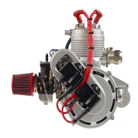
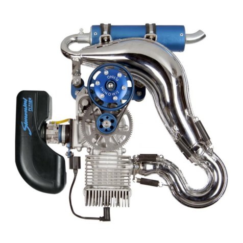
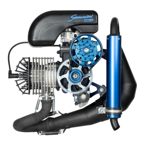
SIMONINI Victor 2 Plus User manual

Operators Manual
Victor 2 Plus / Victor 2 Super

CONTENTS
SAFETY .................................................................................................................................................... 1
1. DESCRIPTION OF ENGINE ...................................................................................................................... 2
1.1 EACH ENGINE IS SUPPLLED WITH: ............................................................................................... 2
1.2 victor2plus and victor2super engines DIMENSIONS.................................................................... 2
1.3 EXPLODED VIEW OF VICTOR 2 PLUS / Victor 2 Super ENGINE ................................................... 3
2. FUEL AND OIL ........................................................................................................................................ 5
2.1 Mixing procedure: ....................................................................................................................... 5
3. GEARBOX OIL ......................................................................................................................................... 6
4. FUEL PUMP............................................................................................................................................ 7
5. BREAKING IN PROCEDURE ..................................................................................................................... 8
6. NORMAL WORKING CONDITIONS ......................................................................................................... 9
7. CARBURETOR ...................................................................................................................................... 10
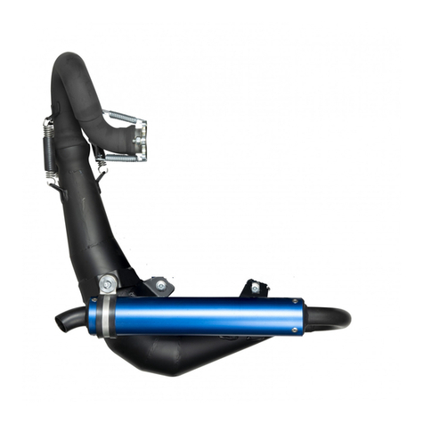
8. EXHAUST SYSTEM ................................................................................................................................ 12
9. REDUCTION GEARBOX ......................................................................................................................... 13
9.1 REDUCTION RATIOS AVAILABLE ................................................................................................ 13
9.2 Exploded View of Simonini Type “C” Gearbox .......................................................................... 14
.............................................................................................................................................................. 14
10. IGNITION SYSTEM ................................................................................................................................ 15
11. SPARK PLUGS....................................................................................................................................... 15
12. LIQUID COOLING SYSTEM: .................................................................................................................. 16
13. AIR FILTERATION SYSTEM ................................................................................................................... 17
14. TORQUE DATA: .................................................................................................................................... 18
15. WEAR LIMITS: ...................................................................................................................................... 19
16. TECHNICAL DATA ................................................................................................................................. 19
16.1 Description ................................................................................................................................ 19
16.2 Temperature ............................................................................................................................. 21
16.4 FUEL SYSTEM: ............................................................................................................................... 22

16.5 OTHER INFORMATION .................................................................................................................. 23
16.6 STANDARD VERSION INCLUDE ..................................................................................................... 23
16.7 WEIGHT ........................................................................................................................................ 23
17. OPERATING LIMITATION ..................................................................................................................... 24
18. WARRANTY CONDITION ...................................................................................................................... 24
ANNEX ....................................................................................................................................................... 26
DECLARATION OF QUALITY ..................................................................................................................... 26

SAFETY
Safety is paramount and all persons using this engine must be responsible for their own safety as
well as the safety of those in the vicinity and those who may be affected.
We include some important safety information and tips; however, this list is neither complete nor
comprehensive.
GENERAL SAFETY POINTERS
1. Never mix fuel in an enclosed space or area where the fumes could be accidentally ignited or
may cause self-combustion.
2. Ensure that all controls work in the correct sense and that you know ON and OFF positions of
the throttle and ignition. Make sure that these are easily accessible when in the process of starting
the engine and that you can operate them in the correct sense instinetive1y and immediately.
3. Ensure that no fuel can be spilled on to the hot exhaust or hot engine parts. Use only safety
approved fuel containers and never transport fuel in an unsafe manner.
4. Do not refuel the aircraft or vehicle with engine running.
5. Check all engine mounts and frames regularly as well as all the drive components, fuel lines,
wiring and fuel and air filters.
6. Check for fuel contamination, air vents and exhausts. Protect engine while it is not in use from
any Contamination entering fuel or carburetor system.
7. Ensure that you remove all storage protection before starting the engine.
8. Maintain your engine in top condition and assume it is going STOP running at any time. Ensure
that you have a way out to safety in event of unexpected failure.
9. Never leave your aircraft with the engine running. You may be held responsible if the aircraft
causes an accident even If you are not in the cockpit.
10. Always maintain the engine / aircraft log and enter any unusual engine behavior. Do not
fly until the problem has been corrected and the corrective action recorded in the logbook.

1. DESCRIPTION OF ENGINE
1.1 EACH ENGINE IS SUPPLLED WITH:
Bing carburetors (BING 54 36mm for Victor 2Plus, BING 54 38mm for Victor2Super), air filters, fuel
pump, exhaust systems, electric starter, reduction gear type “C” with elastic joint on primary gear, system
to charge battery in flight.
1.2 VICTOR2PLUS AND VICTOR2SUPER ENGINES DIMENSIONS

1.3 EXPLODED VIEW OF VICTOR 2 PLUS / VICTOR 2 SUPER ENGINE
Exploded view of Victor 2 engines. Part list as numbered items.

VICTOR 2/01 KIT ENGINE SCREWS
VICTOR 2/49P PISTON PIN
VICTOR 2/02 EXHAUST MANIFOLD AND SPRINGS
VICTOR 2/50 COMPLETE CRANKSHAFT AND ROD
VICTOR 2/03 COMPLETE SET OF GASKETS
VICTOR 2/50A CONNECTING ROD CAGE
VICTOR 2/04 CYLINDER GASKET
VICTOR 2/50B BIG END CAGE
VICTOR 2/05 CYLINDER
VICTOR 2/50D COMPLETE CONNECTION ROD (INCL.54)
VICTOR 2/06 BIG O-RING CYLINDER
VICTOR 2/51 COMPLETE SET OF SEALS
VICTOR 2/07 COMPLETE SET OF SCREWS FOR CYLINDER
VICTOR 2/52 COMPLETE SET OF SEEGERS
VICTOR 2/08 CYLINDER HEAD
VICTOR 2/53 COMPLETE SET OF BEARINGS
VICTOR 2/09 SET WASHER FOR CYLINDER HEAD
VICTOR 2/60 COMPLETE IGNITION
VICTOR 2/10 SET NUTS FOR CYLINDER
VICTOR 2/60A
COIL
VICTOR 2/11 LITTLE O-RING FOR CYLINDER
VICTOR 2/61
CROWN WHEEL FOR STARTER
VICTOR 2/12 SET SCREW FOR WATER
VICTOR 2/62
SPARK PLUG WIRE
VICTOR 2/13 WATER RUBBER MANIFOLD
VICTOR 2/63
SPARK PLUG BR9ES
VICTOR 2/14 MANIFOLD FOR WATER
VICTOR 2/64
EXHAUST SYSTEM
VICTOR 2/17 WATER PUMP
VICTOR 2/65
THERMOSTATIC VALVE AND SUPPORT
VICTOR 2/18 CRANK-CASE COVER IGNITION
VICTOR 2/66
RECTIFIER
VICTOR 2/23 BELT FOR WATER PUMP
VICTOR 2/67
EXHAUST GASKET
VICTOR 2/25 DOUBLE PULLEY FOR WATER PUMP
ITEMS FOR VICTOR 2 PLUS
VICTOR 2/28 CRANK-CASE FOR IGNITION
VICTOR 2P/05
CYLINDER
VICTOR 2/31 REED VALVE
VICTOR 2P/08
CYLINDER HEAD
VICTOR 2/32 RUBBER MANIFOLD
VICTOR 2P/41
CENTRAL CRANK-CASE
VICTOR 2/34 BING 54 CARBURETTOR
VICTOR 2P/50
COMPLETE CRANK-SHAFT AND ROD
VICTOR 2/38 AIR FILTER
ITEMS FOR VICTOR 2 SUPER
VICTOR 2/39 REED VALVE GASKET
VICTOR 2S/05
CILINDER
VICTOR 2/41 CENTRAL CRANK-CASE
VICTOR 2S/08
CYLINDER HEAD
VICTOR 2/42 WASHER-PRESSURE OUTLET
VICTOR 2S/41
CENTRAL CRANK-CASE
VICTOR 2/48 ELECTRIC STARTER by MITSUBA
VICTOR 2S/49
COMPLETE PISTON AND RINGS 82mm
VICTOR 2/49 COMPLETE PISTON AND RINGS
VICTOR 2S/49S
TWO RINGS 82mm
VICTOR 2/49S TWO RINGS
VICTOR 2S/50
COMPLETE CRANK-SHAFT AND ROD
VICTOR 2/49C SET PISTON CIRCLIP

2. FUEL AND OIL
The VICTOR 2 PLUS / Victor 2 Super engine uses unleaded or leaded petrol at least 96 octane
rating. The engine requires the petrol to be premixed with two-stroke oil.
STOP: Do not run the engine without ensuringthat it is correctly loaded (e.g. propeller is mounted).
Fuel contamination can be a major cause of engine failure. Ensure that your fuel container is clean
inside before you use it to fill up with fuel or oil.
Filter all fuel that goes into the fuel container. Also use a filter when transferring fuel from fuel
container into the aircraft tanks. The Victor 2 Plus / Victor 2 Super engine is designed to run on
unleaded petrol or leaded petrol or avgas mixed with 2 Semi-synthetic Oil.
The Oil to be premixed with fuel must meet or exceed the specifications API, TC, JASO, FC.
It is recommended only to use a semi- synthetic 2-stroke oil like Bardahl VBA or equivalent.
Use of Semi- Synthetic Oil pre-mixed in the petrol / avgas will greatly reduce the buildup of carbon
deposits in the cylinder heads and pistons. This will increase your service intervals.
2.1 MIXING PROCEDURE:
Use a clean container of known volume.
Pour Oil into container.
Pour Fuel into the can using a fine mesh filters.
Close container cap firmly and shake container for a few moments so that the oil and fuel are mixed
properly.

3. GEARBOX OIL
Reduction Gearbox Oil in the Simonini Type "C" reduction gearbox. Recommended Oil is
9OWX/140EP. The quantity required to fill the gearbox is 170cc with gear box upright and 225cc
with gear box down.
Warning: Do not run the engine without sufficient oil in the Gear Box.
On the side of the Gear Box there are two Allen Screws which are used to inspect and indicate the
level of oil in the gear box.
It is always the lower of the 2 screws that indicates maximum oil level. The lower Allen screw can
be carefully opened to check that the oil leve1 is sufficient. Do not over fill above this level. When
the instillation requires the gearbox to be fitted with the propeller shaft below the crankshaft, the
oil filler cap and the oil drain plug are interchanged.
Stop: Ensure before every flight that you have sufficient oil in the gearbox.
Max Oil Level 177cc
Gear Box UP
Max Oil Level 225cc
Gear Box Down

4. FUEL PUMP
The Victor 2 Plus /Victor 2 Super engine comes equipped with a Mikuni Membrane Pump. This is
a pneumatic pump operated by the pressure pulses from the crankcase of the engine.
Install the pump 3 - 4 cm higher than the crankcase pressure outlet. This will prevent a build-up of
fuel / oil mix in the lower compartment of the fuel pump, which in turn may lead to less efficiency.
The length of the tube, which connects the engine crankcase depression to the fuel pump, should
be as short as possible, ideally less than 10/15 cm long.
If your aircraft fuel tank is located more than 70cm below the carburetor and fuel pump, install an
electric pump near the fuel tank. This pump will help push the fuel up to the membrane pump and
prevent vapor locks pump subsequent engine failures. Stop: The maximum fuel pressure exerted
by the electric fuel pump should not exceed 0.3 bar.
When fitting an electric booster fuel pump ensure that there is fuel filter installed in line before the
pump. This will prevent the electric pump from clogging up with foreign material, which may
result in fuel starvation and resultant engine stoppage.
The electric booster fuel pump must be of the type where it allows fuel to pass through even when
it is not working.
Example of electric fuel pump that may be
used as a Booster pump

5. BREAKING IN PROCEDURE
DO NOT RUN THE ENGINE WITHOUT PROPELLER AND EXHAUST SYSTEM
Each Simonini Victor 2 plus / Victor 2 super engine is assembled and run in at the factory.
Each engine is subjected to a dynamic test. The engine is securely mounted on a test bench and a
suitable propeller installed on it.
The engine is started and kept running for up to 4 hours at variable speeds.
Temperatures and power outputs are regularly checked while the engine is being run.
The customer/user is not required to do any running or breaking in procedures on the engine.
The carburetors are set at the factory for the ideal settings.
When the engine is mounted on your aircraft, ensure that both carburetor settings are equal when
installing the throttle and choke operating cables.
Adjust the carburetor slides until you get an 8 mm gap under the slides when visible from the air
filter side.
Turn the carburetor airscrews fully close and then unscrew them by 1 to 1. 5turns.
With the throttle completely closed and the choke in, you can start the engine: do not run the
electric starter for more than 5seconds. Once the engine runs, please wait for 4/5seconds then you
have to leave the choke progressively until the engine runs correctly and regularly.
Once the engine has been warmed gradually (1-2minutes) accelerate and stabilizing the gas at
about 3800/4000rpm.
Now you have to reduce the engine rev at the minimum (adjusted at 2000/2100rpm per minute). If
it does not work this way, please adjust the two idle screws and set them better.

Once the synchronization of the throttle cables and idle screws, you should check the maximum
throttle opening (TO BE DONE WITH THE ENGINE OFF!), making sure that they open fully
and simultaneously.
If you followed the above procedure the result will be an engine without any starting problem and
with a regular minimum rev and very stable.
Carburetion tests with maximum rpm on ground and rpm cruising: color spark plugs comparison
and EGT check. How to proceed:
After having anchored the aircraft correctly, warm up the engine, accelerate to full speed
5700/5800 for 15-20 seconds, check the EGT instrument, simultaneously turn off the engine and
remove the gas.
Remove the spark plugs of the exhaust side: if the color is light brown, the temperature is about
600°C. If the color is dark brown, the temperature is about 500°C.
If necessary, change the main jet up to get an EGT temperature at 520/540°C.
Repeat the same procedure to run the engine at cruising for 15/20seconds at 4800/5200RPM
(depending on the type of installation). Check the EGT temperature, turn off the engine and at the
same time removing the gas.
Remove again the spark plugs of the exhaust side. Surely, the color will be lighter than the previous
reading. Then increase the needle jet size to get an EGT temperature of 520/540°C (this
temperature is lower than the recommended one because while cruising there is an increase of
about 20/30°C, given the greater flow of air to the carburetors)
We suggest you to use a 3-bladed propeller Kiev by 182cm with pitch 1.3, already tested by us.
Attention: this is an indicative measure as it depends on the engine and aircraft type. Remind the
runs range: on ground 5700 / 5800 rpm, while in flight 6100 / 6200rpm.

6. NORMAL WORKING CONDITIONS
It is recommended to use as much as gas your aircraft needs, it depends on your requirements and
as occasion may require. Reach height as soon as possible, above all if you are flying with a delta
motor.
Do not exceed maximum 6200 RPM. Do not run the engine in the climb out at Full Open Throttle
for more than 3 minutes.
Idling rpm should be 2000 rpm. Less than this may cause unnecessary vibrations. Higher idling
rpm will cause a reduction in the fuel / air mixture enrichment in the starting circuit of the
carburetor and may make cold engine start-ups difficult.
Before shut down, the engine should be run until any heat build-up from previous high power
settings (e.g. taxi back to hangar) has dissipated. Run the engine at 3000 rpm for 2 minutes and
then at 2000 rpm or smooth idle speed for a short while.
Do not idle for prolonged periods (e.g. holding point checks) as the normal rich conditions at this
carburetor setting may cause high carbon deposits on the spark plugs and piston rings causing
fouling. At low revolutions, the vibrations are high and the loads on the propeller, gearbox, and
drive train and should be avoided for longevity of the engine.
7. CARBURETOR
The Victor 2 Plus / Victor 2 Super engine is equipped with 2 Bing Double Float Carburetors. The

Bing Carburetor is a piston type carburetor with float Chamber.
The following methods and combinations can adjust the Carburetor.
1. By Main Jet / Idle Jet / Needle Jet of various sizes.
2.The Jet Needle size and position can also be varied.
3.The Air / Fuel Mixture screw, Carburetor piston stop height can be changed.
When anyone of the above components or settings is changed, it affects the others so that other
small adjustments may be required.
Each Carburetor must be fitted with the slide axis at right angles in relation to the crankshaft axis,
both from the top and the intake side, to ensure equal fuel distribution to both cylinders.
When you receive the engine from Simonini Flying, the engine has been run in and the
carburetor settings checked.
NOTE: The Simonini Factory is at 600 meters above Mean Sea Level; thus, when the engine
is run in at the Factory, it is set to produce maximum power at that altitude. If you are to
operate the engine at a very different altitude, you may need to retune the Carburetor
mixture settings to produce optimum power.
Stop: When you attach the throttle cable and choke cables, please ensure that you have both the
carburetor slides moving exactly equally up and down in unison. If not, it will cause the engine to
run rough or worse malfunction. The throttle control mechanism must enable the carburetor slides
to attain their full open position.
Ensure that aircraft movement or controls movement does not affect the movement of throttle and
choke cables. This may cause the throttle settings to change inadvertently.
Ensure that Air filters and Exhausts and Radiators are installed in place before starting the engine.
They must be in place to produce proper carburetion for the engine.
Special operating conditions or extreme altitude and or climatic changes will require different
Jetting. Contact your dealer for the correct carburetor jets setting. The Victor 2 Plus / Victor 2
Super engine is fitted With "Reed Valves" between the Carburetors and the crankcase. These
valves add to the efficiency of the engine in controlling carburetion and fuel economy.

8. EXHAUST SYSTEM
The Simonini Engines produce a high power output to weight ratio with the help of very highly
tuned exhaust systems. The exhaust system is manufactured in theSimonini factory for each engine
type and in different models to adapt it to several aircraft models.
Stop: Do not attempt to make any changes to the Simonini Exhaust Systems.
Any changes will invalidate the warranty and may severely reduce the performance and power
output of the engine. Any changes will affect adversely the fuel economy as well as the reliability
of the engine.
Vibrations caused by incorrect mounting and fixing of the exhaust system will result in a reduced
life span of the exhaust system.
Ensure that the entire system is free from vibrations through the entire range of power settings.
Ensure that there is no harmonic resonance or vibration present due to the engine, propeller and
aircraft combination. This means that you must mount the exhaust system on shock resilient
mounts.
Ensure that the ball joints of the various exhaust system components are lined with an antigalling
product (e.g. copper loaded grease or graphite dry lubricant).
Secure the exhaust system to the aircraft.
Secure all the springs by loosely wire locking them. We furnish silicon tubes to ensure a longer
and better life to the springs.
9. REDUCTION GEARBOX
The Simonini Victor 2 Plus / Victor 2 Super engine comes fitted with the Simonini Type "C"
gearbox. There are various ratios that the customer cans specify when ordering. Please confirm
and check that you have the correct reduction gear ratio for your combination of propeller, aircraft
and engine.

9.1 REDUCTION RATIOS AVAILABLE
2.54:1
2.76:1
3.06:1
3.47:1
4.00:1
The Gear Box Input Shaft is fitted with a rubber "Donut" elastic joint that acts as a vibration
damper.
The Reduction Gearbox may be fitted with the drive output propeller shaft above or below the
crankshaft axis.
9.2 EXPLODED VIEW OF SIMONINI TYPE “C” GEARBOX

10. IGNITION SYSTEM
The Simonini Victor 2 Plus / Victor 2 Super engine is equipped with a breaker-less 12 Volts 170w
Ducati Capacitor-Discharge Dual Ignition.
The Ignition system consists of:
1. F1ywheel Magneto Generator.
2. Two twin Ignition Coils with Integrated Control Circuit.
3. Magnetic Pickups which act as Triggers for the Sparks.
4.

11. SPARK PLUGS
The Victor 2 Plus / Victor 2 Super is installed with 2 NGK B9ES Spark Plugs on each Cylinder.
The gap on the spark plug electrodes should be between 0.45 to 0.5 mm.
As the fuel and oil that you use may vary from time to time; check the condition of all the spark
plugs on your engine regularly. Remember to check and clean the spark plug caps. At the same
time check for evidence of shorting caused by build-up of fretting residues (powdery substance).
Clean and re-gap plugs if necessary. Gap = 0.45mm to 0.5mm
Always replace all the four plugs at the same time. When replacing spark plugs after checks, you
should put them back in the same position. This will prevent possible damage to the cylinder head
threads. Always use anti-seize paste when instilling spark plugs.
If plugs are sooty with oil deposits, the engine is running too cold (i.e. too rich). The Carburetion
and Air Filters should be checked for cleanliness.
It is recommended only to use a semi- synthetic 2-stroke oil like Bardahl VBA or equivalent. Use
of Semi- Synthetic Oil pre-mixed in the petrol / avgas will greatly reduce the buildup of carbon
deposits in the cylinder heads and pistons.
If plugs have whitish deposits with evidence of melt droplets; it maybe a lean mixture. Ifcarburetor
calibration is correct and no evidence of manifold leaks neither lack of fuel nor incorrect float
settings is found, check the cooling system.
The temperature measured under the spark plugs Cylinder Head Temperature (CHT) on each
cylinder must not exceed 120° C. at full power.
The temperature of the coolant exiting the cylinder heads (water Temperature) at maximum power
must not exceed 80° C.
The Normal Operating temperature range for the Coolant / Water temperature is between 55° C to
65° C.
Do not take-off until the Water temperature has reached 50° C.

12. LIQUID COOLING SYSTEM:
The Simonini Victor 2 Plus / Victor 2 Super engine is liquid cooled. The engine is equipped with
an integral water pump, the water pump is belt driven. The coolant is pumped around the cylinders
and cylinder heads under pressure from the water pump. There are 2 finned heat dissipaters which
route the coolant water to and from the radiator. The top heat dissipater is fitted with a thermostat
designed to open at 57° C. The other end of the top heat dissipater is to be fitted with the coolant
temperature sender.
The radiator fitted to the Victor 2 Plus / Victor 2 Super engine must be between 1000 to 1100 cm²
radian surface areas. The radiator mountings and security must be ensured before every flight.
The coolant should be a mixture of 70% water and 30% anti-freeze suitable for aluminum. If
necessary, change the anti-freeze percentage to ensure the effective cooling.
The maximum coolant temperature must not exceed 75°C. If on takeoff the coolant temperature
exceeds 50°C. You must reduce power until the temperature drops below 50° C.
The radiator filler/ expansion bottle is of the pressure relief type with an over flow tube. Ensure
that the overflow tube is routed into a bottle to capture any coolant, which may overflow due to
expansion.
WATER PUMP SHOWN WITH DRIVING BELT, COVER PLATE AND HOSE PIPES.
Radiator Filler / Expansion Bottle with
Pressure Cap.

13. AIR FILTERATION SYSTEM
The Victor 2 Plus / Victor 2 Super engine has one air filter on each carburetor intake. The air filter
is made from a special fabric enclosed inside a wire mesh cage.
The air filters must be clean and oiled with light filter oil. The filter oil prevents moisture from
clogging the filter cloth.
14. TORQUE DATA:
M12
STARTER FLY WHEEL
70NM
M8
WATER PUMP BODY
22NM
M8
STARTING STATOR COIL SUPPORT
23NM
M8
STARTER MOTOR
23NM
M8
CYLINDER HEAD
23NM
M10
CYLINDER BASE
50NM
M6
REDUCTION GEAR BOX COVER
10NM
M8
REDUCTION FLANGE
23NM
M8
REDUCTION SEMI-BOX
23NM
M8
REDUCTION CRUSE
30NM
M10
RUBBER FLEXIBLE COUPLING (DONUT)
60NM
M12
REDUCTION GEAR NUT
70NM
This manual suits for next models
1
Table of contents
Other SIMONINI Engine manuals
