Simpsons SC213 User manual

CAPTAIN 280 4WD
Pioneer of The Mini Tractor
ENGINE SERVICE MANUAL (SC213)

SIMPSONS
DIESEL ENGINES
SC213 - Tractor Application
WITH
MECHANICAL FUEL INJECTION PUMP
PROVISIONAL
A MEMBER OF THE AMALGAMATIONS GROUP
861/862, Anna Salai, Chennai - 600 002.

2
SC213 Diesel Engines
To ensure the best results from your engine and
to safeguard your own guarantee, fit, only genuine
SIMPARTS
Title : SC213 Workshop Manual - Tractor Application.
1st Issue : March, 2015
Published by : Service Department, Simpson & Co. Ltd., Chennai - 2. INDIA
Every effort is made to ensure that the information
contained in this book is correct at the date of publication
but due to continuous developments, the manufacturers
reserve the right to alter the specification without notice.

3
SC213 Diesel Engines
This manual is designed to be of assistance to
all personnel concerned with the maintenance
and overhaul of the SIMPSONS Diesel Engine.
It presents a complete and detailed description
of the engine, together with precise instruction
on servicing and overhaul procedure and
dimensions which should be closely followed
when overhauling any part of the engine to the
Manufacturers standards.
Effective maintenance can only be carried out if
thepersonnelconcernedarefullyconversantwith
the various components of the engine. Before
maintenance operations are commenced, this
manual should be carefully studied, and it should
at all times be kept where it will be needed in the
FOREWORD
workshop.
A School of Instruction is maintained at
our Product Training Centre. For Details Contact
Service Department, M/s. Simpson & Co. Ltd.,
Chennai 600 002. INDIA
ENGINE PARTS
WheneverpartsareorderedforSIMPSONSEngine,
it is essential that the fullest information possible
is given, always quote the engine number, type of
application and where possible the part number
and description.

4
SC213 Diesel Engines
CONTENTS
Section Description Page No.
A GENERAL INFORMATION … 6
B ENGINE VIEW … 7
ENGINE NUMBER LOCATION … 9
C TECHNICAL DATA … 10
MANUFACTURING DATA AND DIMENSIONS … 11
D OPERATION AND MAINTENANCE … 17
E PREVENTIVE MAINTENANCE … 19
F FUEL SYSTEM … 25
G COOLING SYSTEM – WATER PUMP … 34
H FRONT OIL SEAL … 36
I FLY WHEEL AND REAR END OIL SEAL … 41
J BALANCER UNIT AND OIL PUMP … 43
K CYLINDER HEAD … 46
L TIMING CASE AND DRIVE … 54
M PISTONS AND CONNECTING RODS … 57
N CRANKSHAFT AND MAIN BEARINGS … 61
O CYLINDER BLOCK AND LINERS … 64
P LUBRICATING SYSTEM … 65
APPROVED LUBRICATING OILS … 66
Q ELECTRICAL EQUIPMENT … 67
R TROUBLE SHOOTING … 68
S SERVICE TOOLS … 86

5
SC213 Diesel Engines
SPECIAL FEATURES
Cylinder Block with Integral Housing and Timing case
Cylinder Head with Integral Inlet Manifold
Single side Servicing
Crankshaft with Crankpins at the same side
Balancer shaft for better balancing of unbalanced masses
SC 213 engines provide a very high backup torque and
an excellent fuel economy with low emission levels.

6
SC213 Diesel Engines
SAFETY
The safety measures that always should be performed in
order to avoid risks that is always present.
All servicing normally be carried out with the engine
stationary.
Do not approach the running engine with loose cloth
or long hair.
Be careful of hot surfaces.
Do not open the radiator filler cap when the engine is hot.
Avoid skin contact with oil, fuel or chemicals that can
cause burn. Long term contact with oil can lead to the
skin problem.
Run the engine only in a well-ventilated area.
When lifting the engine use the lifting eyes that are fitted
to the engine.
Never work alone when removing heavy parts.
When cleaning the engine with high-pressure water,
never direct the jet at seals, rubber hoses or electrical
components.
Always prevent diesel or oil from contacting rubber parts
or tubing
Caution: Warns of a risk of injury, serious damage to
the product or serious malfunctions could occur if the
instruction is not followed.
Important: Is used to draw attention to things that could
cause damage to or malfunction of the product.
Note: It is used to draw attention to important information
to facilitate procedure or handling.
TOOLS AND MEASURING EQUIPMENT
Be sure that all necessary tools and equipments are
available before starting work.
Use special tools where they are specified.
Never drop the tools
Use correct tools as specified.
REMOVAL OF PARTS:
First find the cause of the problem and then determine
whether removal or disassembly is required before
starting the job.
INSPECTION OF PARTS:
Eachpartwhen removedshould becarefully inspectedfor
malfunction, deformation, damage and other problems.
All disassembled parts required for reassembling should
be carefully stored.
Ensure to separate and correctly identify the parts to be
replaced from those that will be used again.
CLEANING OF PARTS FOR REUSE:
All parts to be used again should be carefully and
thoroughly cleaned by an appropriate method.
PARTS
When replacing parts, use genuine SIMPSON parts.
Oil seals, Gaskets, O-rings, Lock washers, split pins and
plastic nuts should always be replaced with new ones.
Standardvaluessuchas torqueandadjustments mustbe
strictly observed in the reassembly of all parts.
FITMENT
Use correct tools, gauges and testers for correct fitment
of the parts to standard value.
ELECTRICAL SYSTEM
Be sureto disconnectthebattery cablesfromthe negative
terminal of the battery
Never pull on the wires when disconnecting connectors.
Section A
GENERAL INFORMATION

7
SC213 Diesel Engines
Section B
ENGINE VIEWS
F.I.P SIDE VIEW
FRONT VIEW

8
SC213 Diesel Engines
ENGINE VIEWS
EXHAUSTSIDEVIEW
REAR VIEW
9
SC213 Diesel Engines
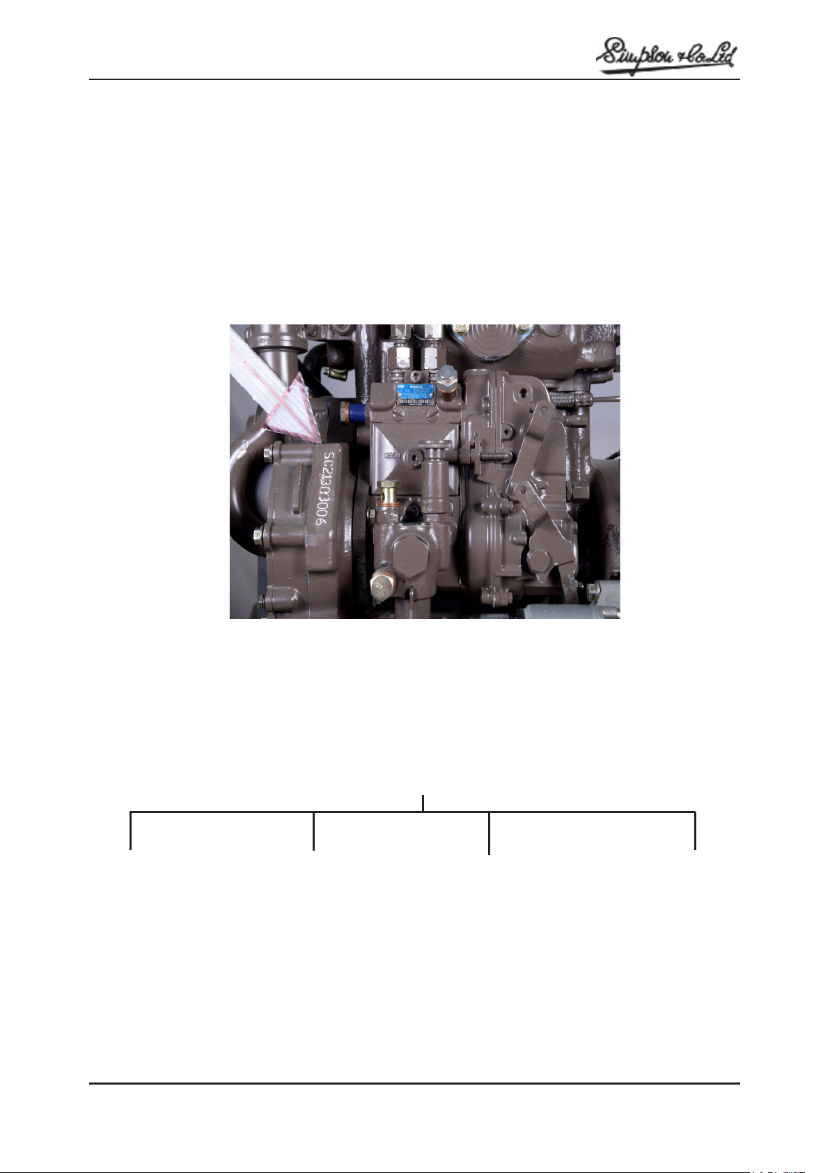
Engine number is stamped on the F.I.P side of the engine on the Timing Case .
When requesting information regarding the engine, the complete engine number should be quoted.
SC213 03006
ENGINE NUMBER LOCATION
SC-Simpsons
Compact
2–No. of
Cylinders
03006
Engine Sl.No.
13–1.29 ltrs (Cube
Capacity)
Note : IF THE ENGINE NUMBER REACHES 99999,ONE DIGIT WILL BE REPLACED BY LETTER “A” AS SHOWN A00001.
When requesting information regarding the engine, the complete engine number should be quoted.

10
SC213 Diesel Engines
Section C
TECHNICAL DATA
Engine Type : 2 Cylinder. 4 Stroke. Inline Water Cooled
Aspiration : Natural
Combustion : Direct Injection
Bore (Nominal dia.) : 3.740 inch (95.0 mm)
Stroke : 3.58 inch (91 mm)
Cubic Capacity : 78.7 cu.inch (1.29 Lts.)
Compression ratio : 18.3 : 1
Rotation : Anti-clock wise from the flywheel end
Firing order : 1, 2
Valve Tip Clearance : 0.006 inch (0.15 mm) inlet and exhaust
Atomiser setting pressure : 250 bar (6 Spray Nozzle)
Inlet valve opens : 12° B.T.D.C.*
Exhaust valve closes : 12°A.T.D.C.**
Total inlet open period : 232°
Total exhaust open period : 236°
Fuel Injection Pump : Bosch inline, flange mounted, pressure feed
lubrication from engine, mechanical governor with
fine adjusting device.
Injection timing : 14° ± 1° B.T.D.C
When No.1 piston at TDC compression stroke.
Fuel feed pump : Integrated feed pump driven by F.I.P camshaft
Application : Tractor - (TREM IIIA)
Engine Rating : 25 HP @ 2500 RPM
APPROXIMATE ENGINE WEIGHTS :
Basic weight (with starter motor & flywheel) : Approximate 148 kg
ENGINE DIMENSION :
Height :31.90 inch/ (810 mm). Length: 30.62 inch (778 mm). Width: 20.00 inch (508 mm)
* B.T.D.C. – Before Top Dead Center ** A.T.D.C. – After Top Dead Center

11
SC213 Diesel Engines
MANUFACTURING DATA AND DIMENSIONS
The following data of clearances and tolerances are given as a guide for personnel engaged in major overhauls and the
figures are those used in the factory for production purposes.
Cylinder Block
Height of cylinder block (Top to bottom faces) … 12.498 / 12.501 inch (317.45 / 317.55 mm)
Parent bore dia. for Cylinder Liner … 3.740 / 3.741 inch (95.00 / 95.02 mm)
Main bearing parent bore … 2.440 / 2.442 inch (62.00 / 62.03 mm)
No. 1 Bore for Camshaft … 1.930 / 1.931 inch (49.025 / 49.050 mm)
No. 2 Bore for Camshaft … 1.939 / 1.949 inch (49.25 / 49.50 mm)
No. 3 Bore for Camshaft … 1.939 / 1.949 inch (49.25 / 49.50 mm)
Balancer Shaft Bore Dia 1 and 2 ... 1.023 / 1.024 inch (26.00 / 26.02 mm)
Pistons :
Type … Aluminum alloy Piston with re-entrant bowl.
Offset of combustion bowl in piston crown should
be on the FI Pump side while assembling piston in
engine. An arrow mark is stamped on piston top
surface for identification. Arrow should face front of
Engine.
Piston Height in relation to cyl. block top face … 0.0138 inch (0.35 mm) - Above block surface /
0.002 inch ( 0.05 mm) - Below block surface
Bore Dia. for Gudgeon Pin … 1.1025 / 1.1027 inch (28.005 / 28.01) mm
Top ring Groove Width … 0.102 / 0.103 inch (2.59 / 2.61 mm)
2nd ring Groove Width … 0.1 / 0.100 inch (2.54 / 2.56 mm)
3rd ring Groove Width … 0.119 / 0.120 inch (3.03 / 3.05 mm)
Piston Rings
Top Compression … Chromium inlaid, cast iron ring)
2nd Compression … Cast Iron. Taper land
3rd Oil Control … Conformable oil control ring
Piston Ring Width
Top and 2nd ring width ... 0.097 / 0.098 inch (2.47 / 2.49 mm)
3rd ring width … 0.117 / 0.118 inch (2.97 / 2.99 mm)
Ring clearance in Piston Groove :
Top ring clearance in Groove … 0.0039 / 0.0055 inch ( 0.10 / 0.14 mm)
2nd ring clearance in Groove … 0.0019 / 0.0035 inch (0.05 / 0.09 mm)
3rd ring clearance in Groove … 0.0015 / 0.0031 inch (0.04 / 0.08 mm)
Ring Gaps
Ring Gap – Top … 0.012 / 0.020 inch (0.30 / 0.50 mm)
Ring Gap – 2nd … 0.025 / 0.037 inch (0.65 / 0.95 mm)
Ring Gap – 3rd … 0.010 / 0.018 inch (0.25 / 0.45 mm)

12
SC213 Diesel Engines
NOTE : The ring gaps given above are for when checking in the unworn portion of the cylinder bore. When
checking ring gaps in a worn bore. 0.003’’ (0.08 mm) should be added to these ring gaps for every 0.011 inch
(0.03 mm) increase in bore diameter
Gudgeon Pin
Type … Fully Floating
Outside dia. of gudgeon pin … 1.102 / 1.1025 inch (27.995 / 28.00 mm)
Fit in piston boss … Transition
Clearance fit in Small end Bush … 0.0011 / 0.0019 inch (0.03 / 0.05 mm)
Small End Bush
Type … ci Steel Backed. Lead Bronze Lined
Outside Dia … 1.220 inch (31.00 mm)
Length … 1.378 inch (35.00 mm)
Inside Dia after reaming … 1.151 / 1.155 inch (29.35 /29.35 mm)
Connecting Rod
Type … “H” Section
Big end Parent Bore Dia … 2.008 / 2.0086 inch (51.006 / 51.019 mm)
Small end Parent Bore Dia … 1.220 / 1.221 inch (31.00 / 31.25 mm)
Big end Width … 1.244 / 1.248 inch (31.60 / 31.70 mm)
Big end side clearance on Crankpin … 0.012 / 0.020 inch (0.3 / 0.5 mm)
Length between bore centers … 5.825 / 5.827 inch (147.975 / 148.025 mm)
NOTE :The numbered side of connecting rod and cap should be on the fuel injection pump side.
Connecting Rod Bearings
Type … Pre-finished. Steel Backed low carbon steel
AluminumTin / Silicon
Inside Dia. (Big end bearing) … 1.949 / 1.950 inch (49.53 / 49.52 mm)
Bearing Running Clearance … 0.0015 / 0.003 inch (0.04 / 0.079 mm)
Recommended sizes in service … 0.010” (0.25 mm); 0.020” (0.51 mm); 0.030” (0.76 mm)
Crankshaft
Material ... Chromium molybdenum alloy steel forging.
Statically balanced. Main journals and crank pins
are induction hardened.
Main Journal Dia. (Std.) … 2.282 / 2.283 inch (57.98 / 58.00 mm)
Crank pin Dia. (Std.) … 1.889 / 1.890 inch (47.98 / 48.00 mm)
Main Journal length - Nos.1 … 1.311 / 1.326 inch (33.30 / 33.70 mm)
Main Journal Length – No.2 … 1.338 / 1.341 inch (34.01 / 34.08 mm)
Main Journal Length – No.3 … 1.330 / 1.346 inch (33.80 / 34.20 mm)
Crankpin length … 1.260 / 1.264 inch (32.00 / 32.10 mm)
Main Journal fillet radii Nos. 1 … 0.098 / 0.118 inch (2.50 / 3.00 mm)
Main Journal fillet radious No. 2 and 3 … 0.098 / 0.118 inch (2.50 / 3.00 mm)
Crankpin fillet radii … 0.098 / 0.118 inch (2.50 / 3.00 mm)
Surface finish (all Pins and Journals) … 0.4 microns (Maximum)
Crankshaft end Float … 0.003 / 0.006 inch (0.07 / 0.15 mm)
Crankshaft rear end Seal … Lip Type
Regrind Under sizes. Main Journal and Crank Pins … 0.010”(0.25mm);0.020”(0.51mm);0.030”(0.76mm)

13
SC213 Diesel Engines
NOTE: When regrinding the crank pin length should not exceed 1.5748 inch (40.00 mm) and the rear main
journal length should not exceed 1.8610 inch (47.27 mm) and Nos.2 and 4 main Journals width should not exceed
1.2275 inch (31.1785 mm) maximum. The maximum permissible undersize is 0.0299 inch (0.76 mm)
Crankshaft Thrust Washers
Type … Steel Back - Low carbon steel - 1.8 mm incl.
Aluminium Tin (or) Copper Lead
Position in engine … Cylinder Block Centre Main Bearing Housing
Thickness-Standard Size … 0.105 / 0.107 inch (2.67 / 2.72 mm)
Thickness-Oversize … 0.1283 / 0.1303 inch (3.26 / 3.31 mm)
NOTE : While locating the Thrust Washers ensure that the plain surface/Steel back is towards the block and the rear
main bearing cap.
Main Bearings
Type … Pre-finished. Steel Back low carbon steel.
AluminiumTin Silicon or Copper Lead
Inside Dia. (fitted) … 2.362 / 2.363 inch (60.02 / 60.03 mm)
Running clearance … 0.0015 / 0.003 inch (0.04 / 0.079 mm)
Recommended size in service … 0.010” (0.25 mm) ;0.020” (0.51 mm) ;0.030” (0.76 mm)
Camshaft
Type … Chilled cast iron
No. 1 Journal Dia. … 1.927 / 1.928 inch (48.95 / 48.975 mm)
No. 2 Journal Dia. … 1.927 / 1.928 inch (48.95 / 48.975 mm)
No. 3 Journal Dia … 1.927 / 1.928 inch (48.95 / 48.975 mm)
Running Clearance – All Camshaft Journals … 0.002 / 0.004 inch (0.05 / 0.10 mm)
Oil way for cam shaft lubrication … From main oil gallary to centre cam journal
Cam Lift - Inlet … 0.393 inch (10 mm)
- Exhaust … 0.393 inch (10 mm)
Camshaft end float … 0.004 / 0.014 inch (0.10 / 0.35 mm)
Cylinder Head
Cylinder head total height … 4.410 inch (112 mm)
Leak Test … 4 Bar for 1 minute
Valve seat angle … Inlet 45° / Exhaust 45°
Permissible cylinder head bow
Transverse and Longitudinal … 0.001 / 0.002 inch (0.03 / 0.05 mm)
Valve Layout ... E, I, E, I
NOTE : Valve stem seal (with Sintered metal insert) is fitted in both inlet and exhaust valves.

14
SC213 Diesel Engines
Inlet and Exhaust Valves
Valve Stem Dia (Inlet) … 0.3101 / 0.3095 inch (6.95 / 6.97 mm)
Valve Stem Dia. (Exhaust) … 0.3096 / 0.3090 inch (6.93 / 6.95 mm)
Clearance fit of valve in guide (Inlet) … 0.0004 / 0.0015 inch (0.01 / 0.04 mm)
Valve face Angle (Inlet) … 45°
Valve face Angle (Exhaust) … 45°
Valve depth above or below cylinder head face … 0.015 inch (0.4mm)
Valve head Dia. Inlet … 1.590 / 1.598 inch (40.40 / 40.60 mm)
Valve head Dia. Exhaust … 1.492 / 1.500 inch (37.90 / 38.10 mm)
Valve Spring
Free length … 1.968 inch (50 mm)
Fitted length … 1.102 inch (28 mm)
Load at fitted length … 250 N (25 kg)
Tappet
Outside Dia. of Shank … 1.061 / 1.063 inch (26.96 / 27.00 mm)
Rocker Shaft
Outside Diameter … 0.629 / 0.630 inch (15.976 / 15.984 mm)
Rocker Lever
Bush Bore Diameter … 0.787 / 0.788 inch (20.00 / 20.02 mm)
Running clearance of Bush on Shaft … 0.011 / 0.002 inch (0.022 / 0.048 mm)
Timing Gears
Crankshaft gear … 20 Teeth
Idler gear … 25 Teeth
Camshaft gear … 40 Teeth
Fuel Pump gear … 40 Teeth
Balancershaft gear … 20 Teeth
Camshaft Gear
Gear Bore Diameter … 0.944 / 0.945 inch (24.00 / 24.013 mm)
Clearance fit of Gear on Spigot … 0.000 / 0.0019 inch (0.00 / 0.05 mm)
Idler Gear and Hub
Bore Dia of gear … 1.025 / 1.026 inch (26.040 / 26.061 mm)
Diameter of hub … 0.984 / 1.024 inch (25.00 / 26.00 mm)
Clearance of gear on hub … 0.002 / 0.003 inch (0.040 / 0.082 mm)
Gear Hub Width … 0.659 / 0.661 inch (16.75 / 16.80 mm)
Bearing length of hub … 1.6019 / 1.5940 inch (40.69 / 40.49 mm)
Gear end-float … 0.002 / 0.006 inch (0.060 / 0.140 mm)
NOTE :The bore and faces of bushes should be finished to the specified dimensions by machining after pressing
the bushes in the gear bore.

15
SC213 Diesel Engines
Crankshaft Gear
Diameter of Bore … 1.4996 / 1.5011 inch (38.090 / 38.13 mm)
Spigot Dia of crankshaft … 1.5005 / 1.5000 inch (38.113 / 38.10 mm)
Transition fit of Gear on Crankshaft … 0.011 / 0.0015 inch (0.03 / 0.04 mm)
Fuel Pump Gear
Diameter of Bore … 48.035 /48.056 mm
Pump adaptor Dia. … 48.000 / 47.975 mm
Clearance fit of gear on spigot … 0.0039 / 0.0022 inch (0.100 / 0.056 mm)
Timing Gear Backlash
All Gears … 0.002 / 0.005 inch (0.06 / 0.14 mm) (min.)
Lubricating Oil Pump
Oil Pump type … Lobe type
Number of inner rotor lobes … 9
Number of outer rotor lobes … 10
Balancer Shaft end float ... 0.003 / 0.006 inch (0.075 / 0.150 mm)
Lubricating Oil Pump Clearances
Inner Lobe to Outer Lobe … 0.0005 / 0.0025 inch (0.01 / 0.06 mm)
Inner Lobe end clearance … 0.0015 / 0.003 inch (0.04 / 0.08 mm)
Outer Lobe end clearance … 0.0005 / 0.0025 inch (0.01 / 0.06 mm)
Outer Lobe to Pump Body … 0.011 / 0.013 inch (0.28 / 0.33 mm)
Lubricating Oil Pressure at maximum engine
speed and normal working temperature … 3.5 kgf/ cms²
Lubricating Oil Relief Valve
Type … Spring Loaded Plunger
Pressure Setting … 3.569 kgf / cm ²
Lubricating Oil Filter
Type … Spin on
Element … Replaceable Paper / Canister
By-pass Valve Setting … 12.94 / 17.06 psi (0.91 / 1.20 kg/ cm²)
Sump Capacity … 1.160 gal (4.391 lts). Sump capacity vary
according to application
Cooling System
Type … Water cooled
Coolant capacity–Engine only … 1.057 gal (4 lts). (approximate)
Thermostat
Type … Wax with bypass blanking
Opening temperature … 73° ± 2°C
Fully open … 83° ± 2°C
Water Pump
Type … Centrifugal
Pulley bore dia … 0.944 inch (24 mm)
Interference fit of pulley on shaft … 0.005 inch (0.121 mm)
Clearance between impeller blades and body ... 0.008 / 0.020 inch (0.2 / 0.5 mm)
Distance between impeller rear face to body … 3.929 inch (99.80 mm)

16
SC213 Diesel Engines
Fuel System
Fuel oil specification … Fuel Oil conform IS : 1460 / 2000 grade special
or Grade ‘A’
Fuel Filter Type … BOSCH single spin on with hand primer
Fuel Feed Pump … Plunger type flange mounted on cylinder block,
driven by engine cam shaft ecentric.
Fuel Injection Pump
Make … BOSCH
Type … Inline
Mounting … Flange mounted to engine timing case
Drive … Gear
Pump Rotation … Anti-clock wise (when viewed from fly wheel end)
Governor … Mechanical with fine adjusting device.
Starter Motor
Make … LUCAS TVS
Type … M70 12 Volts
No. of teeth on pinion … 10
Starter Cable Resistance … 0.0017 ohms maximum
Rotation … Clockwise when viewed from fly wheel end
Note : The above electrical data is general and can vary with individual application

17
SC213 Diesel Engines
Section D
OPERATION AND MAINTENANCE
PREPARATION FOR STARTING
Check the coolant level with radiator.
Check the oil level in engine sump.
Check the fuel oil level in the tank
Check the battery is fully charged and that all electrical
connections are properly made and all circuits in order.
STARTING THE ENGINE
Turn starter switch in clockwise direction to the “ON”
position and then to start position
As soon as the engine starts, release the switch to the
“ON” position.
TO STOP THE ENGINE
1.Pull the stop control knob and hold until the engine
ceases to rotate.
2. Push and ensure the stop control knob returns to the
run position.
3. Turn start switch to the ‘Off’ position.
Note: Where an electrical shut off solenoid is provided,
turn the start key to “Off” position to stop engine.
Always be sure that the starter pinion has stopped
revolving before re-engaging the starter.
RUNNING-IN PROCEDURE
It is not necessary to gradually run-in a new engine and
any prolonged light load running during the early life of
the engine and in fact prove harmful to the bedding in
of piston rings and liners.
Full load can be applied on a new engine as soon as the
engine is used, provided that the engine coolant is first
allowed to reach a temperature of at least 140oF (60oC).
POST-DELIVERY CHECKOVER
After a customer has taken delivery of his diesel engine, it
isadvisable, ageneral check-overof theengine becarried
out after the first 25 hours in service.
It is also recommended that the following procedure
be adopted where an engine has been laid up for a
considerable period before it is again put into service.
1.Drain lubricating oil sump and re-fill up to the full mark
on the dipstick with new clean oil (Do not overfill).
2. Renew the lubricating oil filter (canister).
3. Check external nuts for tightness.
4. Check/ adjust valve tip clearances to 0.15 mm (0.006’’
to inlet and exhaust valve in cold.
5. Check fuel pipes from tank to fuel injection pump for
leaks.
6. Check for lubricating oil leaks and rectify if necessary.
7. Check hose clips for tightness.
8. Check cooling system for leaks and inspect radiator
water level.
9. Check fan belt for tension.
10.Carryouttestto checkgeneralperformanceofengine.
11. Check engine mounting bolts for tightness.
12.Checkthe electricalequipmentsuch asrateofcharge,
effectiveness of connections and circuits, etc.
Thereaftermaintenanceperiods shouldbe inaccordance
with the instructions given. (Ref. Section E).
PRESERVATION OF LAID-UP ENGINES
It is recommended that the following procedure
be adopted and applied immediately the unit is
withdrawn from service:
1. Thoroughly clean all external parts of the engine.
2. Run the engine until well-warmed. Stop the engine
and drain lubricating oil from sump. Remove the oil filter.
3. Drain coolant from radiator and engine cylinder
block.
4. Replace the oil filter, fill sump to correct level
with clean, new lubricating oil or with a suitable
preservative fluid.
5. Remove atomisers and spray into cylinder bores
100 ml of lubricating oil divided between the
cylinders.
6. Turn engineslowly overcompressionand replace
atomisers.
7. Remove air cleaner intake pipe and Remove
exhaust pipe and seal opening in manifolds.
8. Disconnect battery and store in fully charged
condition. Before storing the battery, terminals
should be treated to prevent corrosion.
The fuel system be drained or charged with a suitable
preservative designed for the prevailing climatic

18
SC213 Diesel Engines
conditions or alternatively, it may be left primed with
normal fuel oil.
If the engine is laid for several months then the fuel oil
contained in the remainder of the fuel system should
also be dispelled and the fuel filter renewed, following
which the system may then be recharged with fresh
clean fuel oil.
Before starting, the engine should be cranked over by the
starter motor with the stop control in the ’off’ position
until oil pressure is recorded or the oil warning light is
extinguished. Do not rapidly accelerate the engine after
initial start; allow it to run at slow speed for approximately
two minutes to ensure good oil circulation before
accelerating to higher speeds.
Note: Where a preservative is used in the lubricating oil
sump, this should be drained off and replaced by normal
lubricant prior to restarting the engine at the end of the
storage period.
FROST PRECAUTIONS
Precautions against damage by frost should be taken if
the engine is to be left exposed to inclement weather
either by adequately draining the water system or where
this is not convenient an anti-freeze of reputable make
and incorporating a suitable corrosion inhibitor may be
used.
The coolant solution containing 25 per cent anti-
freeze manufactured to BS 3151 in water in a properly
maintained engine should maintain its anti-freeze and
anti-corrosive properties throughout the winter season
and in general, a safe life of 12 months may be
reasonably expected.
Remove the radiator pressure cap, drain the cooling
system by opening the radiator drain tap and the cylinder
block drain tap.
When draining the cooling system ensure that the engine
is in level.
Operatorsare advisedto takeprecautions whenoperating
in temperatures below freezing point:
1. Before starting the engine, turn the fan and water
pump by hand. If freezing has taken place, this
should free any ice formation.
2. If it is impossible to turn the pump by hand, the
radiator and engine should be filled with warm
water.
After an anti-freeze solution has been used, the cooling
system should be thoroughly flushed in accordance
with the manufacturer’s instructions before refilling with
normal coolant.

19
SC213 Diesel Engines
DAILY OR EVERY 8 HOURS WHICHEVER
OCCURS FIRST:
Keep Engine Clean.
Check level of coolant.
Check oil level in sump.
Check oil pressure.
Check for water in the fuel filter.
EVERY 250 HOURS OR 12 MONTHS:
Drain and renew lubricating oil.
Renew lubricating oil filter (canister).
Check drive belt tension.
Clean and Renew lubricating oil from wet type air cleaner.
Clean fuel lift pump pre-filter (where fitted).
Check engine for leakage of oil and water.
EVERY 500 HOURS OR TWO YEARS.
Check hoses and clips.
Check atomisers.
Check valve tip clearances.
Examine valve springs.
Inspect valve rocker shaft assembly for lubrication.
Clean and treat battery terminals.
Replace fuel filter element. (Spin on type).
EVERY 1,000 HOURS:
Drain fuel tank, remove and clean.
Flush radiator with clean water.
DRY TYPE AIR CLEANER MAINTENANCE
In extreme dust condition clean the air cleaner daily.
Check Air restriction indicator in air cleaner (when engine
is running).
1st Cleaning after 100 Hrs.
2nd cleaning after 200 Hrs.
Discard the element if found complete choked.
Main Outer Element can be cleaned twice only with
pressurised air (applying from inside to outside) before
replacement.
Safety cartridge/ inner element is to be replaced along
with the third fitment of Main outer Element.
Remove the dust every after 50 Hrs. from dust unloader
by press opening the lip.
Note : The interval of cleaning the air cleaner element
depends on operating conditions; therefore under
extremely dusty conditions, the time interval to be
shortened.
The correct maintenance of the air cleaner will help in
extend the life of the engine.
FUEL FILTERS MAINTENANCE
(Make: BOSCH , India)
Do not clean filter canister.
Drain filter bowls after every 125 hrs. of operation by
loosening sludge screws (wherever provided), until clean
fuel flows out.
Fuel filter single canister type spin on element should be
replaced after every 500 hours of operation.
Section E
PREVENTIVE MAINTENANCE
Table of contents


