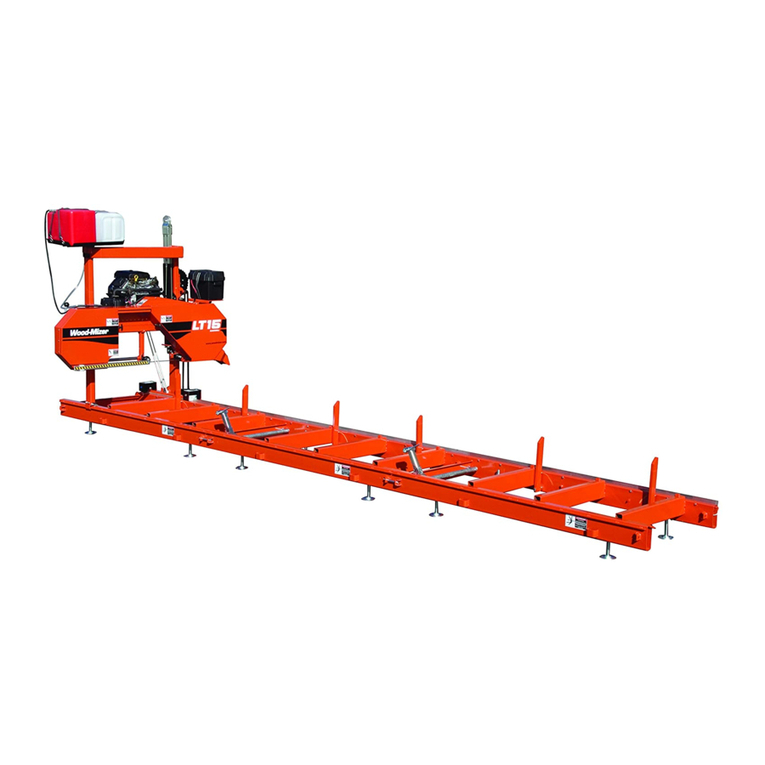
woodmizer LT28 G19 Guide

LT28 G19 Engine
Safety, Operation, Maintenance
& Parts Manual
Used with
LT28G19 rev. A1.00 - A6.16
Safety is our #1 concern!
Form #1343

Active Patents assigned to Wood-Mizer, LLC
Wood-Mizer, LLC has received patents that protect our inventions which are a result of a dedication to
research, innovation, development, and design. Learn more at: woodmizer.com/patents
©2022 Wood-Mizer LLC
Printed in the United States of America, all rights reserved. No part of this manual may be reproduced in any form by
any photographic, electronic, mechanical or other means or used in any information storage and retrieval system with-
out written permission from
Wood-Mizer, LLC
8180 West 10th Street
Indianapolis, Indiana 46214
California
Proposition 65 Warning
WARNING:
Breathing gas/diesel engine exhaust exposes you to chemicals known to
the State of California to cause cancer and birth defects or other reproductive harm.
Always start and operate the engine in a well-ventilated area.
If in an enclosed area, vent the exhaust to the outside.
Do not modify or tamper with the exhaust system.
Do not idle the engine except as necessary.
For more information go to www.P65warnings.ca.gov.
WARNING:
Drilling, sawing, sanding or machining wood products can expose you to
wood dust, a substance known to the State of California to cause cancer. Avoid inhaling
wood dust or use a dust mask or other safeguards for personal protection.
For more information go to www.P65Warnings.ca.gov/wood.

Table of Contents Section-Page
Table of Contents WMdoc112122 iii
TOC
SECTION 1 ABOUT THIS MANUAL 1-1
SECTION 2 OPERATION 2-1
2.1 Starting The Engine................................................................................2-1
SECTION 3 MAINTENANCE 3-1
3.1 Maintenance ...........................................................................................3-1
3.2 Safety......................................................................................................3-1
3.3 Cooling System ......................................................................................3-1
3.4 Air Filter & Pre-Cleaner.........................................................................3-1
3.5 Fuel Filter ...............................................................................................3-2
3.6 Battery ....................................................................................................3-2
3.7 RPM Adjustments ..................................................................................3-2
3.8 Miscellaneous Maintenance ...................................................................3-2
SECTION 4 REPLACEMENT PARTS 4-1
4.1 Fuel Tank................................................................................................4-1
4.2 Fuel Tank Rev. A6.10 - A6.11 ...............................................................4-2
4.3 Fuel Tank Rev. A3.00 - A6.09 ...............................................................4-3
4.4 Fuel Tank Rev. A3.00 - A6.09 ...............................................................4-4
4.5 Fuel Tank Rev. A1.00 - A2.01 ...............................................................4-6
5.6 Engine Assembly....................................................................................5-1
5.7 Throttle/Clutch Assembly ......................................................................5-3

1
1-1 WM doc 11/21/22
SECTION 1 ABOUT THIS MANUAL
This manual is provided as a supplement to the equipment manufacturer’s manuals. This manual provides information specific
to the use of this equipment on the Wood-Mizer® sawmill. Refer to the sawmill operator’s manual and manufacturer's manual
before attempting to operate this equipment.
IMPORTANT! Read the sawmill operator’s manual and engine manufacturer’s
manual for instructions and safety precautions before operating this equip-
ment.
The information and instructions given in this manual do not amend or extend the limited warranties for the equipment given at
the time of purchase.
ENGINE COMPONENTS
Muffler
Starter
Air Filter
Serial Number/
Engine Type
280033

Operation
Starting The Engine 2
Operation WM doc 11/21/22 2-1
SECTION 2 OPERATION
2.1 Starting The Engine
DANGER! Always be sure the blade is disengaged and clear the path of the
blade before starting the engine. Failure to do so will result in serious injury or
death.
Operate your engine/machine only in well ventilated areas.Exhaust gases can
cause nausea, delirium and potentially death unless adequate ventilation is
present.
Never operate an engine with a fuel or oil leak. The leaking fuel or oil could
potentially come in contact with hot surfaces and ignite into flames.
WARNING! Do not operate engine without proper and operational spark
arrester/muffler. Sparks emitted from the engine exhaust could ignite sur-
rounding materials, causing serious injury or death.
CAUTION! EPA Compliant Gas Tanks Only: Always relieve all fuel pressure
inside the tank prior to filling or connecting fuel fittings. Failure to do so may
result in fuel spillage.
EPA Compliant Gas Tanks Only: Disconnect the fuel tank when not in use, or
engine flooding or fuel spillage may result.
1. Close the engine choke by moving the choke lever to the start position.
2. Turn the key switch to the START position and release. Release the key switch to the RUN position after the engine starts.
3. When the engine starts, slowly open the choke all the way by moving the choke lever to the off position.
ENGINE SHUTOFF
1. Disengage the clutch handle to stop the blade if necessary.
2. Run the engine for 15 seconds with no load, then turn the key switch to the OFF position.

Maintenance
Maintenance
3
3-1 WM doc 11/21/22 Maintenance
SECTION 3 MAINTENANCE
3.1 Maintenance
Refer to the manufacturer’s manual for maintenance intervals and procedures unless otherwise instructed in this manual. Fol-
low the manufacturer’s recommendations for dusty conditions.
NOTICE This manual only provides information about additional procedures or
procedures to be performed at different time intervals than found in the manu-
facturer's manuals. Refer to the manufacturer's manual for complete mainte-
nance instructions.
3.2 Safety
Use caution when performing maintenance or service to the engine.
DANGER! Always be aware of and take proper protective measures against
rotating shafts, pulleys, fans, etc.
Always stay a safe distance from rotating members and make sure that loose
clothing or long hair does not engage rotating members.
Never touch or perform service functions on a hot engine.
WARNING! Remove the blade before performing any engine service. Failure
to do so may result in serious injury.
Wear proper (eye, breathing, hand, and foot) safety equipment when perform-
ing service functions.
Clean sawdust from all guards, vents, control boxes, or any area
where sawdust may gather after every shift. Failure to do so may
result in fire, causing death or serious injury.
3.3 Cooling System
Wash the engine or brush off sawdust and debris every 50 hours of operation.
Clean any screens, cooling fins, and all external surfaces.
Remove any dust, dirt, or oil.
See engine manual for further instructions.
3.4 Air Filter & Pre-Cleaner
Service the pre-cleaner every four hours of operation by gently shaking excess sawdust and debris from the foam piece.
Clean the air filter (air cleaner element) and pre-cleaner (element wrapper) every eight hours of operation.
Replace the air filter (cleaner) every 200 hours of operation.
Replace the pre-cleaner (element wrapper) every 2000 hours of operation.
See the engine manual for further instructions.
Maintenance
Fuel Filter 3
Maintenance WM doc 11/21/22 3-2
3.5 Fuel Filter
Replace the fuel filter every 100 hours of operation or as required for engine performance.
3.6 Battery
Check the battery electrolyte level every 50 hours of operation. See manufacturer’s manual for instructions.
DANGER! Batteries expel explosive gases. Keep sparks, flames, burning
cigarettes, or other ignition sources away at all times. Always wear safety
goggles and a face shield when working near batteries. Failure to do so
will cause serious injury.
WARNING! Battery posts, terminals and related accessories contain lead
and lead compounds, chemicals known to the State of California to cause
cancer and reproductive harm. Wash hands after handling.
3.7 RPM Adjustments
WARNING! Remove the blade before performing any engine service. Fail-
ure to do so may result in serious injury.
Check the RPM with a tachometer every 200 hours of operation.
Before checking the RPM, make sure belt and brake strap tensions are correct (See Sawmill Maintenance).
Check oil, fuel, and coolant levels.
Make sure the throttle cable does not affect the engine RPM when the clutch handle is disengaged. Make sure the cable is
not bent or kinked.
1. Start the engine to measure the low-end RPM.
2. Refer to the engine manual to adjust the low-end RPM.
3. Engage the clutch handle to throttle the engine and measure the high-end RPM.
The high-end RPM is factory-set at 3750. Readjust the throttle cable if necessary to increase or reduce the high-end engine
speed.
3.8 Miscellaneous Maintenance
Inspect the spark plugs every 100 hours of operation.
Remove any deposits and adjust gap if necessary.
Review the manufacturer's engine manual for maintenance intervals.
See engine manual for further information.
Engine High End RPM Low End RPM
G19 3750 1800
TABLE 3-1

Replacement Parts
Fuel Tank
4
4-1 WM doc 11/21/22 Replacement Parts
SECTION 4 REPLACEMENT PARTS
4.1 Fuel Tank
REF PART # DESCRIPTION COMMENTS QTY.
103816 TRAY ASSEMBLY, LT28/35 FUEL TANK 1
1103810 Weldment, Fuel Tank Tray 1
2103867 Cover, Fuel Tank 1
3103878 Tank, 5 Gallon Low Pro EPA Fuel 1
4061250 Grommet, Shut Off 1
5061251 Gas Cap, LT15 1
6061252 Valve, Slosh 1
7061253 Grommet, Slosh Valve 1
8074943 Fitting, Fuel Pick-Up With Shut-Off 1
9F05006-15 Bolt, 5/16-18 x 1/2” Hex Head Grade 5 4
10 F05007-73 Bolt, 3/8-16 x 3” Hex Head Grade 5 3
11 F05010-10 Nut, 3/8-16 Hex Nyloc 3
12 F05011-3 Washer, 3/8” Flat SAE 6
13 F05011-13 Washer, 5/16” Split Lock 4
14 F05011-17 Washer, 5/16” SAE Flat 4
R02423-1 Hose, Fuel 3/16" EPA 15G CARB 6 Ft
R02423-2 Hose, Fuel 1/4" EPA 15G CARB 6 Ft
1
2
5
3
7
4
6
8
9
13
14
10
11
12
280061C

Replacement Parts WM doc 11/21/22 4-2
Replacement Parts
Fuel Tank Rev. A6.10 - A6.11 4
4.2 Fuel Tank Rev. A6.10 - A6.11
REF PART # DESCRIPTION COMMENTS QTY.
076479 TRAY ASSEMBLY, LT28 GAS CAN 1
074643 Tank Assembly, 6 Gallon Gas Service 1
1076478 Tank, Gasoline Available in assemblies only. 1
2015583 Fitting, 1/4” NPT Male Quick Disconnect 1
3015582 Fitting, Female Quick Disconnect Barb 1
4P649 Clamp, 7/32” - 1/2” Hose 2
5076480 Tray Weldment, LT28 Fuel 1
6F05005-34 Bolt, 1/4-20 X 1” Carriage 2
7F05010-21 Nut, 1/4-20 Swaged 2
8P11668 Strap, 20 Rubber W/Hooks 2
9F05007-29 Bolt, 3/8-16 x 2 3/4” Hex Head 2
10 F05011-3 Washer, 3/8” SAE Flat 2
11 F05010-10 Nut, 3/8-16 Hex Nylon Lock 2
R02423-2 Hose, Fuel 1/4" EPA 15G CARB 6.1 Ft
1
3
2
4
5
6
7
8
910 11
280060

Replacement Parts
Fuel Tank Rev. A3.00 - A6.09
4
4-3 WM doc 11/21/22 Replacement Parts
4.3 Fuel Tank Rev. A3.00 - A6.09
REF PART # DESCRIPTION COMMENTS QTY.
076479 TRAY ASSEMBLY, LT28 GAS CAN 1
074643 Tank Assembly, 6 Gallon Gas Service 5 gallon gas can assemblies are
available only for customers
with sawmills and edgers manu-
factured prior to 2010 (See Sec-
tion 4.4).
1
1076478 Tank, Gasoline Available in assemblies only. 1
2015583 Fitting, 1/4” NPT Male Quick Disconnect 1
3015582 Fitting, Female Quick Disconnect Barb 1
4P649 Clamp, 7/32” - 1/2” Hose 2
5076480 Tray Weldment, LT28 Fuel 1
6F05005-34 Bolt, 1/4-20 X 1” Carriage 2
7F05010-21 Nut, 1/4-20 Swaged 2
8P11668 Strap, 20 Rubber W/Hooks 2
9F05007-29 Bolt, 3/8-16 x 2 3/4” Hex Head 2
10 F05011-3 Washer, 3/8” SAE Flat 2
11 F05010-10 Nut, 3/8-16 Hex Nylon Lock 2
R02423-2 Hose, Fuel 1/4" EPA 15G CARB 6.1 Ft
1
3
2
4
5
6
7
8
910 11
280060-2

Replacement Parts WM doc 11/21/22 4-4
Replacement Parts
Fuel Tank Rev. A3.00 - A6.09 4
4.4 Fuel Tank Rev. A3.00 - A6.09
REF PART # DESCRIPTION COMMENTS QTY.
049138 TRAY ASSEMBLY, LT28 GAS CAN 1
A12285 Tank Assembly, 5-gallon Red Gasoline Customers with sawmills and
edgers manufactured in 2010
and later need to use new EPA
approved 3 or 6 gallon gas can
assemblies (See Section 4.2).
1
1P12167 Tank, 5-Gallon Red Fuel Available in assemblies only. 1
2P12172 Pickup, 9" Fuel 1
3P09683 Cap, 3 or 5-Gallon Fuel Tank 1
4P12175 Fitting, 1/4" NPT Plastic Female Discon-
nect
1
5P10367 Fitting, 3/8” NPT Hex Plug 1
6P642 Hose, 1/4” ID Fuel 4 Ft
7P649 Clamp, 7/32 - 1/2 Hose 2
8P12176 Fitting, 1/4" NPT Plastic Male Disconnect 1
9048600 Tray Weldment, LT28 Fuel 1
10 F05005-34 Bolt, 1/4-20 X 1” Carriage 2
11 F05010-21 Nut, 1/4-20 Swaged 2
12 P11258 Strap, 24 Rubber W/Hooks 2
13 F05007-29 Bolt, 3/8-16 x 2 3/4” Hex Head 2
14 F05011-3 Washer, 3/8” SAE Flat 2
1
2
3
4
5
6
7
7
8
9
10
11
12
13
14 15
280048B

Replacement Parts
Fuel Tank Rev. A3.00 - A6.09
4
4-5 WM doc 11/21/22 Replacement Parts
15 F05010-10 Nut, 3/8-16 Hex Nylon Lock 2
REF PART # DESCRIPTION COMMENTS QTY.

Replacement Parts WM doc 11/21/22 4-6
Replacement Parts
Fuel Tank Rev. A1.00 - A2.01 4
4.5 Fuel Tank Rev. A1.00 - A2.01
REF PART # DESCRIPTION COMMENTS QTY.
049138 TRAY ASSEMBLY, LT28 GAS CAN 1
A12285 Tank Assembly, 5-gallon Red Gasoline 1
1P12167 Tank, 5-Gallon Red Fuel Available in assemblies only. 1
2P12172 Pickup, 9" Fuel 1
3P09683 Cap, 3 or 5-Gallon Fuel Tank 1
4P12175 Fitting, 1/4" NPT Plastic Female Discon-
nect
1
5P10367 Fitting, 3/8” NPT Hex Plug 1
6P642 Hose, 1/4” ID Fuel 4 Ft
7P649 Clamp, 7/32 - 1/2 Hose 2
8P12176 Fitting, 1/4" NPT Plastic Male Disconnect 1
9049137 Tray Weldment, LT28 Fuel . 1
10 F05005-34 Bolt, 1/4-20 X 1” Carriage 2
11 F05010-21 Nut, 1/4-20 Swaged 2
12 P11258 Strap, 24 Rubber W/Hooks 2
13 F05007-87 Bolt, 3/8-16 x 1” Hex Head Grade 5 3
14 F05011-4 Washer, 3/8” Split Lock 3
1
2
3
4
5
6
7
7
8
9
10
11
12
13
14
15
280034

Replacement Parts
Fuel Tank Rev. A1.00 - A2.01
4
4-7 WM doc 11/21/22 Replacement Parts
15 F05011-3 Washer, 3/8” SAE Flat 3
REF PART # DESCRIPTION COMMENTS QTY.

Replacement Parts WM doc 11/21/22 5-1
Replacement Parts
Engine Assembly 5
5.6 Engine Assembly
REF PART # DESCRIPTION COMMENTS QTY.
P12393 COVER, ENGINE 1
049055 ENGINE ASSEMBLY, LT28 GAS 19HP 1
1016899 Engine, 19HP Kohler #PA62590 Available in assemblies only. 1
2006907 Filter, Kohler Air #47-083-03 1
3006931 Pre Cleaner, Kohler #24-083-02 1
P12757 Plug, RC12YC Kohler Spark #12-132-02 2
4014717 Filter, Kohler Oil #52-050-02 1
5P12758 Filter, Kohler Fuel #24-050-13 1
061371 Starter, Kohler Engine KH# 25 098 21S 1
048391 Pump, Kohler Fuel #24-393-16S 1
061150 Switch, Ignition G18/25 1
6038432 Bushing, 1 1/8” SH 1
7047742 Pulley, 3V5.6 x 2” SH 1
8F05011-48 Washer, 7/16” Split Lock 2
9F05007-145 Bolt, 7/16-14 x 1” Hex Head Grade 5 2
10 016493 Plate, Engine Guard 1
11 047750 Plate, Throttle Cable Mount 1
12 047749 Cable, LT15 G25 Throttle 1
13 016033 Spring, Throttle 1
14 015952 Spring, Throttle Extension 1
15 P10082 Hose, 3/8” NPT Oil Drain 1
16 P04332 Cap, Oil Drain Hose 1
061072 Switch, G18/G25 Ignition Plastic 1
1
2
3
4
5
6
7
8
10
9
11
12 17
19
20
18
21
22
14
13
15
16
23
280035

Replacement Parts
Engine Assembly
5
5-2 WM doc 11/21/22 Replacement Parts
17 F05007-119 BOLT, 3/8-16 X 1 3/4” HEX HEAD GRADE 5 4
18 F05011-3 WASHER, 3/8” SAE FLAT 4
19 F05010-10 NUT, 3/8-16 HEX NYLON LOCK 4
20 048237 SUPPORT WELDMENT, DRIVE BELT 1
21 F05007-118 BOLT, 3/8-16 X 3/4” HEX HEAD GRADE 5 1
22 F05010-19 NUT, 3/8-16 SELF-LOCKING HEX 1
23 047751 BELT, 2/3VFL900 DRIVE 1
061326 CARB KIT, G18 DE-ICING 24 755 64S 1
REF PART # DESCRIPTION COMMENTS QTY.

Replacement Parts WM doc 11/21/22 5-3
Replacement Parts
Throttle/Clutch Assembly 5
5.7 Throttle/Clutch Assembly
REF PART # DESCRIPTION COMMENTS QTY.
1065574 BLOCK WELDMENT, LINKAGE CLUTCH/BRAKE 1
2F05012-16 PIN, 3/16” X 1 1/4” ROLL 1
3016486 BUSHING, 5/8” ID X 7/8” OD X 1 1/4” LONG FL
BRONZE
2
4049340 SHAFT, LT28 THROTTLE 1
5034815 ACTUATOR WELDMENT, THROTTLE LT15D&G 1
6F05007-68 SCREW, 3/8-16 X 3/8” SOCKET HEAD CUP PT
SET
2
7034818 LINKAGE, THROTTLE LT15D&G 1
8F05005-15 BOLT, 1/4-20 X 1/2” HEX HEAD 1
9F05010-21 NUT, 1/4-20 SWAGED 1
10 P737 BUSHING, 1” X 1 1/4” X 3/4” FLANGED BRONZE 2
11 034608 PIVOT WELDMENT, CLUTCH/BRAKE 1
034605 LINKAGE ASSEMBLY, W/BEARING 1
12 034604 Boss Weldment, Clutch/Brake Linkage 1
13 016486 Bushing, 5/8” ID x 7/8” OD x 1 1/4” Long
Flanged Bronze
1
038778 NUT ASSEMBLY, 1/2-13 SPRING LOCKING 1
14 F05010-31 Nut, 1/2-13 Hex Jam 1
15 038777 Nut, 1/2-13 Spring Lock 1
16 046975 Spring, .72” OD x .576” ID x 1.25L Compres-
sion
1
12
3
13
4
3
5
6
7
8
9
10
10
11
12
14
17
18 19
20
21
22
20
23
21
24
25
33
32
26
27
28
31
30 29
280059-1C
15
16

Replacement Parts
Throttle/Clutch Assembly
5
5-4 WM doc 11/21/22 Replacement Parts
17 F05010-127 Nut, 1/2-13 Half Nylon Lock 1
065874 BRAKE/CLUTCH ASSEMBLY 1
18 065873 Arm Weldment, Clutch/Brake 1
19 F05007-124 Bolt, 3/8-16 x 2 Hex Head Grade 5 1
20 F05010-10 Nut, 3/8-16 Hex Nyl Lock 2
21 F05011-3 Washer, 3/8” Flat SAE 3
22 F05010-25 Nut, 3/8-16 Swaged 1
23 034810 Spring, Idler Arm LT15/D/E/G 1
24 034602 Idler, 4" O.D. x 3/8” Bore 1
25 F05007-125 Bolt, 3/8-16 x 2-1/2” Hex Head Grade 5 1
26 016488 Block, LT15 Brake 2
27 F05004-2 Bolt, #10-24 x 1” Socket Head Cup 4
28 F05010-14 Nut, #10-24 Keps 8
29 F05004-282 Screw, 10-24 x 5/8” FSHC 4
30 065872 Plate, Brake Adjustment 2
31 F05011-18 Washer, #10 SAE Flat 4
32 F05010-29 NUT, 3/8-16 JAM 1
33 F05007-18 SCREW, 3/8-16 X 1 1/4 SHOP SET 1
REF PART # DESCRIPTION COMMENTS QTY.
Table of contents
Other woodmizer Engine manuals

woodmizer
woodmizer D24 Guide

woodmizer
woodmizer D35 Series Guide

woodmizer
woodmizer G15 Guide

woodmizer
woodmizer LT28 D19 Guide

woodmizer
woodmizer LT35 Guide

woodmizer
woodmizer G26 Guide

woodmizer
woodmizer D10 Guide

woodmizer
woodmizer D17 Guide

woodmizer
woodmizer LT40 MH Series Guide

woodmizer
woodmizer D35 Series Guide

woodmizer
woodmizer D19 Guide

woodmizer
woodmizer LT30 Guide

woodmizer
woodmizer LT28 G25 Guide

woodmizer
woodmizer D10 Guide

woodmizer
woodmizer D19 Guide

woodmizer
woodmizer D17 Guide

woodmizer
woodmizer LT70 Series Guide

woodmizer
woodmizer D34 Guide

woodmizer
woodmizer LT28 D17 Guide

woodmizer
woodmizer LT28 Guide