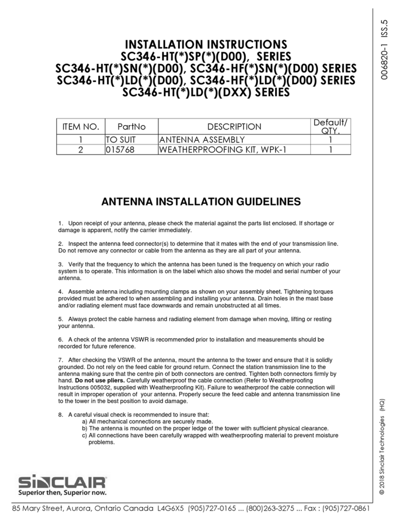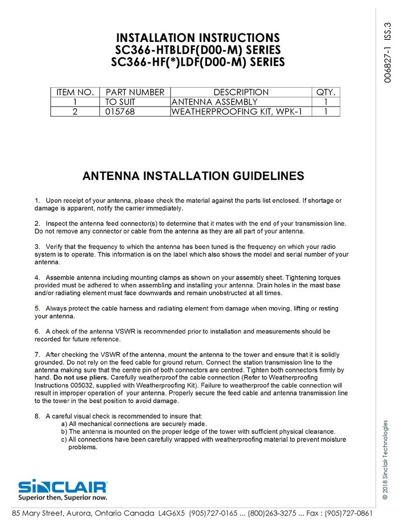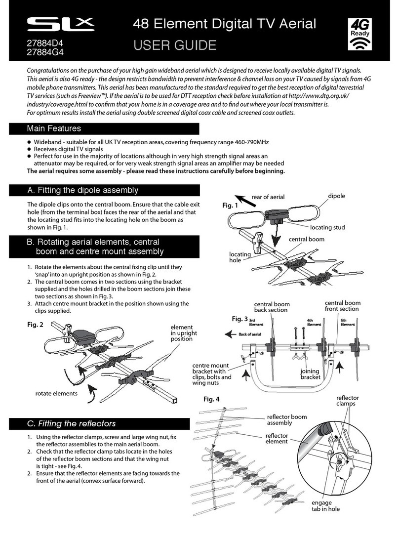
MATERIAL CHECK LIST
SUPPLIED
ITEM PART NO. DESCRIPTION QTY. SINGLE QTY. DUAL
1 TO SUIT ANTENNA ASSEMBLY AND CONNECTOR 1 2
2 6009263 #8-32 x ½ SK HD, SS 4 8
3 6010210 #8 LOCK-WASHER, EXT-TOOTH 4 8
4 8003384 TIE WRAP 10 20
5 8016647 TUNNING TOOL 1 1
6 6001484 8-18 x 5/8” SQ. SK. PAN HD ZINC 6 12
7 TO SUIT POWER DIVIDER - 1
NOT SUPPLIED
ITEM DESCRIPTION
1 2” WIDE “Gorilla Tape®” OR RQUIVALENT
2 CORDLESS DRILL WITH NO. 2 SQUARE HEAD BIT
3CONNECTOR CRIMPER AND TRIMING TOOLS
4VNA ANALYZER WITH APPROPRIATE CONNECTOR ADAPTER
NOTE: Every vehicle is different in style. The following guide is for installation in
most common vehicles.
STEP 1: ASSIGNING ANTENNA LOCATION
NOTE: Using an automotive hoist is recommended for an easier access and safety.
STEP 2: VEHICLE PREPARATION
NOTE: Install the antenna as high as possible from the ground
2.1 Remove any obstructions if required to access the interior (eg: bottom shield, wheel well shield).
2.2 Locate the antenna on a vehicle frame that is connected to the main body to ground the
antenna tuning box.
BOTTOM SHIELD
The antenna whip should reach
an inside surface of a nonmetallic
bumper
Have a reachable
access for tuning
screws
ANTENNA WHIP
INPUT CABLE VEHICLE FRAME
TUNING BOX
WHEEL WELL SHIELD VEHICLE FRAME (INSTALLATION AREA)
• The most important part of the installation is to determine the antenna location on a vehicle.
• An SUV will have more open areas as opposed to a low-profile sport vehicle.
• The most ideal locations for a single and dual antenna installation are shown below.
SINGLE ANTENNA VERSIONS
OPTION 1 OPTION 2
DUAL ANTENNA VERSIONS
OPTION 3 OPTION 4
006842 ISS-1 006842 ISS-1


