6
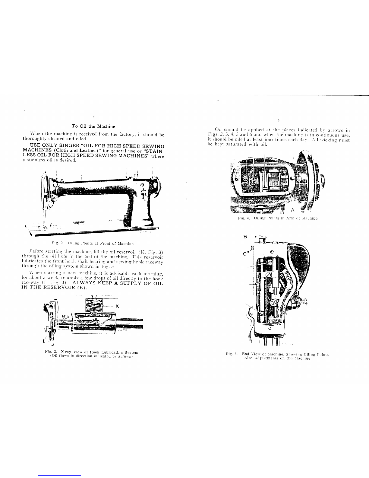
Fig.
G.
Oiling
Points
in
Base
of
1\Iachine
Also
Adjustments
on
the
l\Iaclline
To
Ensure
Perfect
Action
of
the
Machine
The
balance
wheel
must
always
turn
over
toward
the
operator.
Do
not
run
the
machine
with
the
presser
foot
resting
on
the
feed
without
cloth
under
the
presser
foot.
Do
not
run
the
111achine
when
both
bobbin
case
and
needle
are
threaded
unless
there
is
material
under
the
presser
foot.
Do
not
try
to
help
the
machine
by
pulling
the
fabric
lest
you
bend
the
needle;
the
machine
feeds
the
work
without
assistance.
The
slide
O\'Cr
the
bobbin
case
should
be
kept
closed
when
the
machine
is in
operation.
7
Needles
l\ecdles
for
l\Iachinc
150\v161
arc
of
Class
an<l
\'
· t
13-
){
ane
y
.)X_
,
sizes 7, 8, 9, 10, 12, 14, 16, 18, 20
and
22.
The
size
of
the
needle
to
be
used
should
be
determined
bv
the
size
of
the
thread
which
must
pass
freely
through
the
eye
<;f
the
needle.
l f
rough
or
uneven
thread
is
used
or
if it
passes
with
difficulty
through
the
eye
of
the
needle,
the
successful
usc
of
the
machi11e \l·ill
!Je
interfered
with.
Orders
for
needles
must
specify
the
quantity
:-equired,
the
size
number,
abo
the
class
and
variety
numbers
c;cparatecl
by
the
let
tcr
:--:..
The
t<Ji!mving
IS
an
example
of
an
intelligible
order:
"100
'\o.
14,
L\.~x21
:\
tTd!t·s."
Tl1e
l!l·'t
results
will
be
obtained
in
u,;ing
the
needle:-;
fm-
ni,;hed
ln· tht• :-;ingcr :-;ewing
.\lacllinc
l·on1pany.
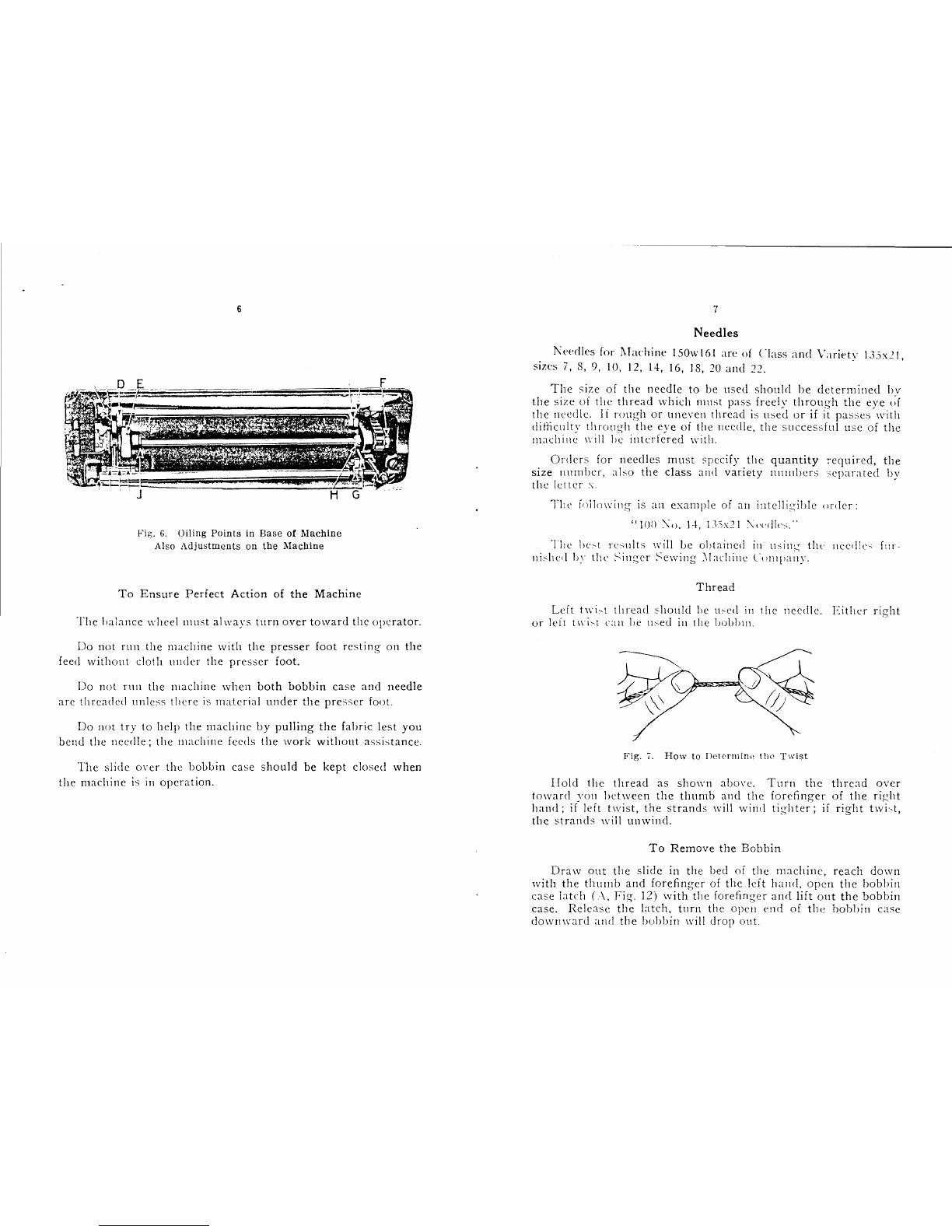
Thread
Left
twi~t
thread
5hould
he
u~ed
in
the
needle.
Either
right
or
left
t11·ic-t
can
!Je
used
in
the
lJObb111.
Fig.
7.
How
to
Iletermirw
the
Twist
IIolcl
the
thread
as
shown
abm·e.
Turn
the
thread
over
toward
you
between
the
thumb
and
the
forefinger
of
the
ric;ht
hand;
if
left
twist,
the
strands
will
wind
tighter;
if
right
twi'>t,
the
~trands
will
unwind.
To
Remove
the
Bobbin
Draw
out
the
slide
in
the
bed
of
the
machine,
reach
down
with
the
thumb
and
forefinger
of
the
leit
hand,
open
the
bobbin
case
latch
(
.\,
Fig.
12)
with
the
forefinger
an<i
lift
out
the
bobbin
case.
Release
the
latch,
turn
the
open
end
of
the
bobbin
case
downward
and
the
bobbin
will
drop
ouL