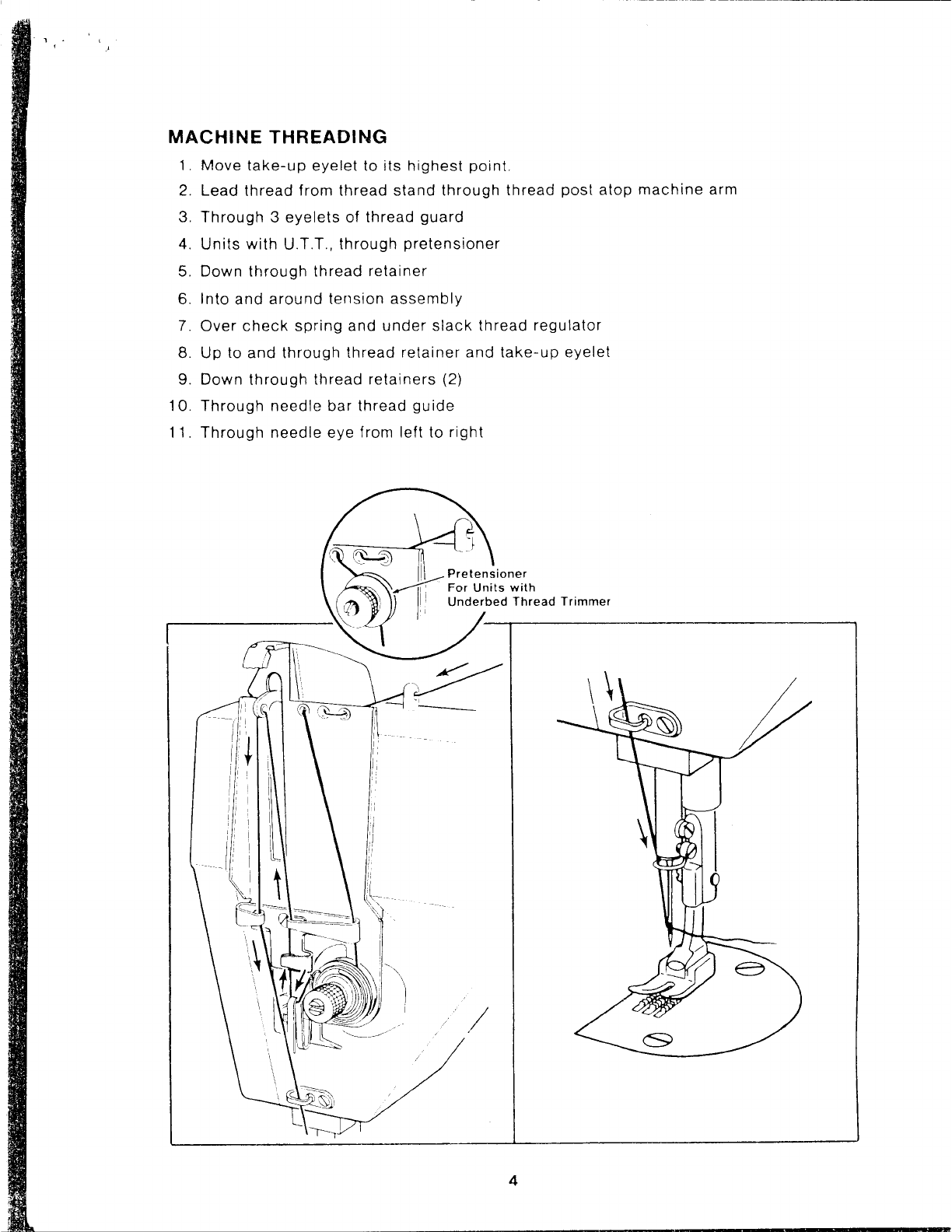
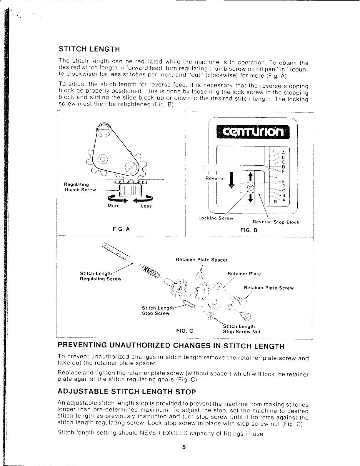
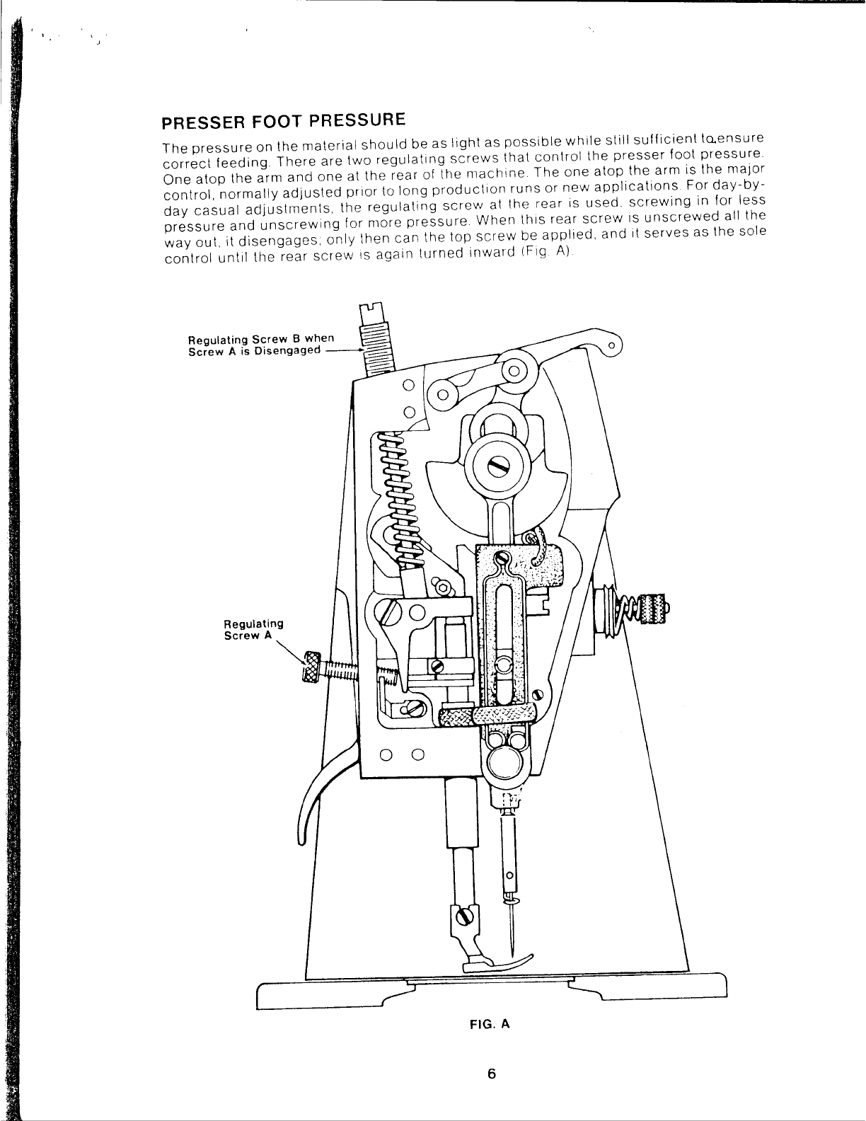
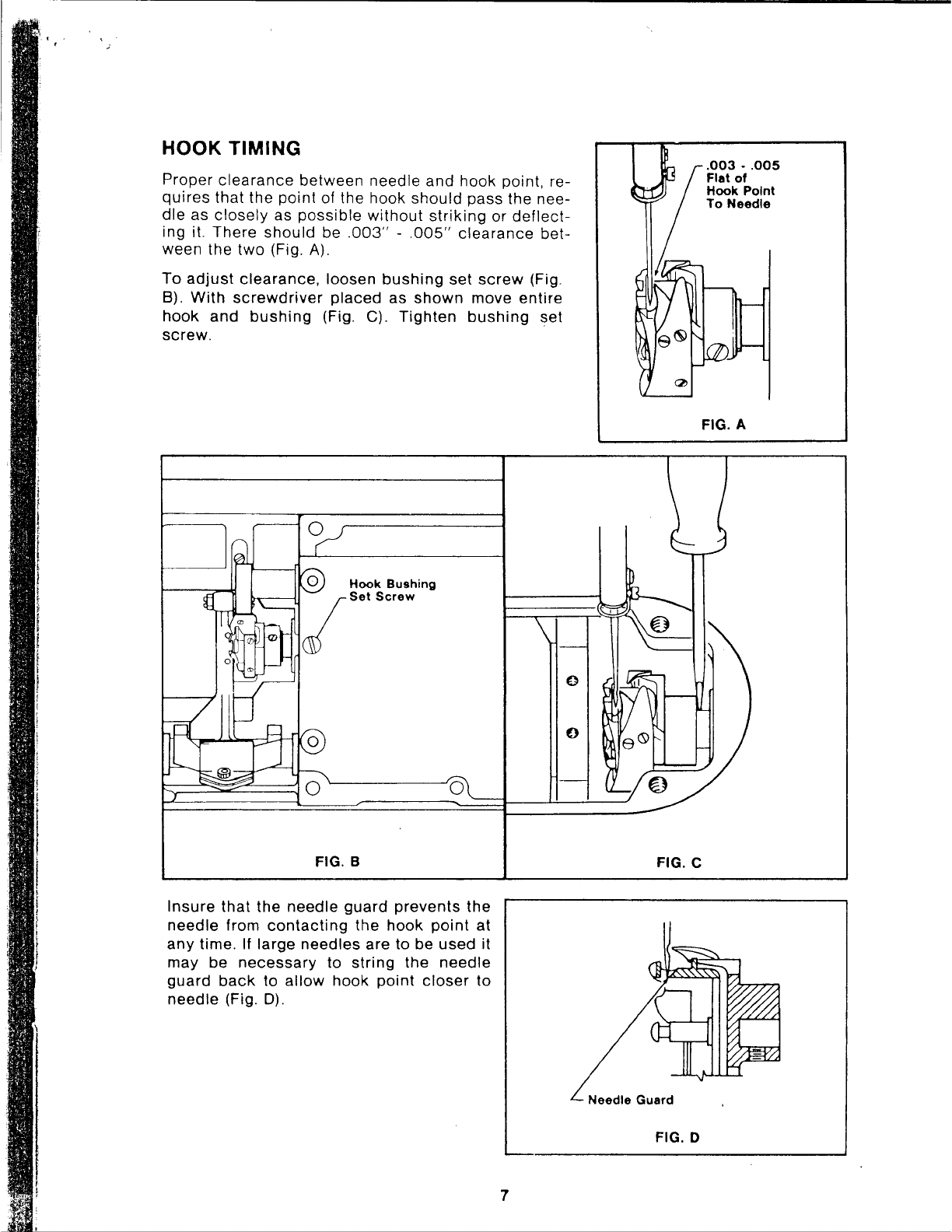
Singer Centurion 121D User manual

SINGER
121D,121C

From the library of Superior Sewing Machine & Supply LLC - www.supsew.com
Form
21624
(Rev
977)
I UAL
I *
Sewing l\llachine
121D CLASS
121C CLASS
Copyright
'
1976
The
Singer
Company
All
Rights
Reserved
Throughout
the
World
•A
Trademark
of THE SINGER
COMPANY
Printed
in U.S.A.

From the library of Superior Sewing Machine & Supply LLC - www.supsew.com
LUBRICATION
Moving
parts
have
either
permanently
sealed
pre-lubricated
ball
or
needle bearings
or
oil
impregnated
bushings
which
require
no manual
lubrication.
The
following
exceptions
are:
HOOK
An oil
reservoir
supplies
oil to the
sewing
hook race and is
filled
through the oil
cup
as
shown,
with
Singer
Type
"C"
oil,
until
the word
"MAX"
is seen in the
indicator
window.
Check
oil level at
indicator
window
daily
before
starting
machine. As oil level decreases,
red
arrow
will
appear
(Fig. A).
-------------------------------
0
FIG. A
1

From the library of Superior Sewing Machine & Supply LLC - www.supsew.com
,.
TO TEST HOOK LUBRICATION
Thread
machine
and
sew
3
yards
of
scrap
material.
Pay
no
attention
to
stitch
quality
or
amount
of
oil
at
this
time.
Remove
material
and
bed
slide.
Run
machine
approximately
one
minute
to
establish
a
uniform
oil
flow.
Without
stopping
machine,
hold
a
piece
of
paper
in
place
under
hook
for
10
seconds.
Remove
paper
and
compare
oil
pattern
with
Fig. B
for
proper
oil
flow.
•,
..
·,'
....
...
. .
..
.
.
. . .
.
•
•-I,
FIG. B
If
there
is
no
trace
of
oil
or
an
excess,
adjustment
should
be
made
with
the oil
metering
screw.
In
order
to
gain
access
to oil
metering
screw,
the
hook
should
be
in
position
as
shown
in Fig.
C.
Turn
oil
metering
screw
clockwise
for
more
oil
and
counterclockwise
for
less
(Fig. D).
Normal
setting
is
made
by
turning
the
metering
screw
all
the
way
in
and
then
backing
the
screw
3
or
4
turns
out.
More
or
less
turns
may
be
required
depending
on
the
operation
being
performed.
Oil
Metering
Screw
Oil
Metering
Screw
More
Oil Less Oil
FIG. C FIG. D
2

From the library of Superior Sewing Machine & Supply LLC - www.supsew.com
If oil flow is not satisfactory, remove hook
assembly
and oil filter.
Check
filter. Oil
wick
should
be replaced
whenever
it has
become
clogged with
lint
or dirt.
An
excess
of oil
sometimes
indicates
that the
filter
wick
has become
detached
from the
screw
or the
screw
is not
securely
tightened.
Inspect
all oil passages to see they have not become
clogged.
011
Filter~
...
:·/•/•'
---
Wick
Hook Assembly
3

From the library of Superior Sewing Machine & Supply LLC - www.supsew.com
l .
'
MACHINE
THREADING
1.
Move
take-up
eyelet
to
its
highest
point.
2.
Lead
thread
from
thread
stand
through
thread
post
atop
machine
arm
3.
Through
3
eyelets
of
thread
guard
4.
Units
with
U.T.T.,
through
pretensioner
5.
Down
through
thread
retainer
6.
Into
and
around
tension
assembly
7.
Over
check
spring
and
under
slack
thread
regulator
8.
Up
to
and
through
thread
retainer
and
take-up
eyelet
9.
Down
through
thread
retainers
(2)
10.
Through
needle
bar
thread
guide
11.
Through
needle
eye
from
left
to
right
ioner
,,
For
Units
with
I!
Underbed
Thread
Trimmer
,,
I'
1:
i,
I
4

From the library of Superior Sewing Machine & Supply LLC - www.supsew.com
STITCH
LENGTH
The
stitch
length
can
be
regulated
while
the
machine
is in
operation
To
obtain
the
desired
stitch
length
in
forward
feed,
turn
regulating
thumb
screw
on oil
pan
"in"
(coun-
terclockwise)
for
less
stitches
per
inch,
and
"out''
(clockwise)
for
more (Fig.
A)
To
adjust
the
stitch
length
for
reverse
feed, it is
necessary
that
the
reverse
stopping
block
be
properly
positioned
This
is
done
by
loosening
the
lock
screw
in the
stopping
block
and
sliding
the
slide
block
up
or
down
to the
desired
stitch
length
The
locking
screw
must
then
be
retightened
(Fig.
B)
Regulating
Thumb
Screw
--~'.
More
Less
FIG. A
Stitch
Length/
,,~'
0
1
~'t.-~
Regulating
Screw
IRB,,
i!tit•J
•I
FIG. B
FIG. C
PREVENTING
UNAUTHORIZED
CHANGES
IN
STITCH
LENGTH
To
prevent
unauthorized
changes
in
stitch
length
remove
the
retainer
plate
screw
and
take
out
the
retainer
plate
spacer.
Replace
and
tighten
the
retainer
plate
screw
(without
spacer)
which
will
lock
the
retainer
plate
against
the
stitch
regulating
gears
(Fig. C)
ADJUSTABLE
STITCH
LENGTH
STOP
An
adjustable
stitch
length
stop
is
provided
to
prevent
the
machine
from
making
stitches
longer
than
pre-determined
maximum.
To
adjust
the
stop,
set
the
machine
to
desired
stitch
length
as
previously
instructed
and
turn
stop
screw
until
it
bottoms
against
the
stitch
length
regulating
screw
Lock
stop
screw
in
place
with
stop
screw
nut
(Fig.
C)
Stitch
length
setting
should
NEVER
EXCEED
capacity
of
fittings
in use.
5

From the library of Superior Sewing Machine & Supply LLC - www.supsew.com
PRESSER
FOOT
PRESSURE
The
pressure
on
the
material
should
be
as
light
as
possible
while
still
sufficient
to.ensure
correct
feeding
There
are
two
regulating
screws
that
control
the
presser
foot
pressure
One
atop
the
arm
and
one
at
the
rear
of
the
machine
The
one
atop
the
arm
is
the
major
control,
normally
adjusted
prior
to
long
production
runs
or
new
applications
For
day-by-
day
casual
adjustments,
the
regulating
screw
al
the
rear
is
used.
screwing
in
for
less
pressure
and
unscrewing
for
more
pressure
When
this
rear
screw
1s
unscrewed
all
the
way
out,
it
disengages,
only
then
can
the top
screw
be
applied.
and
it
serves
as
the
sole
control
until
the
rear
screw
1s
again
turned
inward
(Fig
A)
Regulating
Screw
B when
c.---c
Screw
A
is
Disengaged -
:::=::
Regulating
Screw
A
0 0
0
FIG. A
6

From the library of Superior Sewing Machine & Supply LLC - www.supsew.com
HOOK TIMING
Proper
clearance
between needle
and
hook point, re-
quires
that the point of the hook
should
pass the nee-
dle
as
closely
as
possible
without
striking
or
deflect-
ing it. There
should
be
.003"
-
.005"
clearance
bet-
ween the
two
(Fig. A).
To
adjust
clearance,
loosen
bushing
set
screw
(Fig.
B).
With
screwdriver
placed
as
shown
move
entire
hook
and
bushing
(Fig. C).
Tighten
bushing
set
screw.
Hook Bushing
Set Screw
FIG. B
Insure
that
the
needle
guard
prevents
the
needle from
contacting
the
hook
point
at
any
time. If large needles are to be
used
it
may be
necessary
to
string
the
needle
guard
back
to
allow
hook
point
closer
to
needle
(Fig.
D).
7
FIG. C
Needle Guard
FIG. D
.003
-
.005
Flat of
Hook Point
To Needle
FIG. A

From the library of Superior Sewing Machine & Supply LLC - www.supsew.com
HOOK
TIMING
CONT'D
Reset
position
finger
so
there
is
.018"
-
.022"
thread
clearance
between
finger
and
basket
(Fig. E).
FIG. E
For
200
Variety Machines
(.085"
Loop Rise)
Loosen
hook
set
screws.
Turn
hand
wheel
in
direction
of
rotation
until
needle
bar
is on
the
rise
stroke
and
the
lowest
mark
is
aligned
with
the
needle
bar
height
indicator
Set
hook
point
to
the
centerline
of the
needle
(Fig.
F)
Tighten
hook
set
screws.
FIG. F
Hook
Point to
Centerline of Needle
For
300
Variety
Machines
(.100"
Loop Rise)
Loosen
hook
set
screws.
Turn
hand
wheel
in
direction
of
rotation
until
needle
bar
is
on
the
rise
stroke
and
the
center
mark
is
aligned
with
the
needle
bar
height
indicator.
Set
hook
point
to
the
centerline
of the
needle
(Fig.
F)
Tighten
hook
set
screws
8

From the library of Superior Sewing Machine & Supply LLC - www.supsew.com
TIMING
FEED LIFTING SHAFT
TO
ARM SHAFT
Manually
rotate
arm
shaft
until
timing
mark
on
counterbalance
aligns
with
timing
mark
on
take-up
stud
connecting
link
(Fig.
A).
FIG. A
Loosen bed
shaft
timing
belt
pulley
set
screws
(Fig.
B)
Hold
pulley
stationary
and
rotate
bed
shaft
until
timing
line
at feed
bar
end
of
shaft
aligns
wiih
timing
mark
on
casting
(Fig.
C).
Timing
marks
alignment
in Fig. A
and
Fig. C
must
occur
simultaneously.
Tighten
pulley
set
screws.
NOTE:
There
are
two
timing
marks
on the bed shaft. The long
timing
mark
is for
drop
feed
machines
and
the
short
timing
mark
is
for
coumpound
feed
machines.
Set
Cl)
Screw
(2)
FIG. B FIG. C
9

From the library of Superior Sewing Machine & Supply LLC - www.supsew.com
FEED DOG SETTING
Centrally
locate
feed
dog
in
throat
plate
slots. Feed
dog
must
not
make
contact
with
throat
plate, as noted.
Align
by
loosening
feed
dog
screws.
Then
retighten
screws
Fig.
A.
FIG. A
I
4
3
4
I
2
LATERAL SETTING:
Loosen feed
bar
carrier
pinch
screw
(Fig. 8).
Shift
feed
bar
as re-
quired
to
locate
feed dog in
throat
plate
slots
as
shown
above.
Ensure
that
feed
bar
does
not
contact
position
finger
(not shown).
Tighten
pinch
screw
and
check
axial
play
at
pen-
dant
link.
Adjust
feed
lifting
shaft
left
or
right
to
minimize
play.
Feed
Bar
Hinge Pin -
(eccentric)
Feed
Bar Hinge
Pin Locking
Screws
Feed
Bar
Carrier
Pinch
Screw
Feed Bar Stud
Locking Nut
\
Feed Bar Stud
-'8
._.,-.--.._..-
(eccentric)
FIG. B
10
Feed
Lifting
Shaft

From the library of Superior Sewing Machine & Supply LLC - www.supsew.com
LENGTHWISE
SETTING:
Adjust
stitch
length
to
longest
stitch
and
loosen
feed
bar
car-
rier
pinch
screw.
Position
so
that
feed
dog
does
not
contact
either
end
of
slots
in
throat
plate
HEIGHT
SETTING:
Loosen
feed
bar
hinge
pin
locking
screws
(Fig. B),
and
turn
ec-
centric
feed
bar
hinge
pin.
Visually
adjust
to
bring
feed
dog
at
maximum
height
above
throat
plate
and
tighten
both
hinge
pin
locking
screws
This
will
locate
the
slot
shown
in
a
vertical
position
(Fig. 1
).
Loosen
feed
bar
stud
locking
nut
(Fig B),
and
turn
eccentric
stud
several
times
You
will
note
that
the
feed
bar
will
rock
back
and
forth.
Visually
position
feed
bar
rock
motion
towards
the
operator
with
slot
in
vertical
position
(Fig 1),
and
tighten
locking
nut.
Slot In
Vertical
Feed
Bar
Stud
/'.!J.!...-
___
Position
(Eccentric)
FIG. 1
11

From the library of Superior Sewing Machine & Supply LLC - www.supsew.com
TO
ADJUST
FEED DOG HEIGHT AT
.043
INCH
(FOR
SEWING
ALL TYPES
OF
MATERIAL
EXCEPT
"WASH
AND
WEAR")
1.
Set
machine
for
sewing
approximately
14
stitches
per
inch.
2.
Loosen
screws
"A"
and
"B"
of feed
bar
carrier
(Fig. 1
).
3.
Insert
screwdriver
into
hole
of
bed
(Fig. 1
),
and turn
eccentric
hinge
pin
"C"
to
bring
feed
dog
at
maximum
height
above
throat
plate
with
slot
positioned
vertically.
4.
Tighten
screws
"A"
and
"B".
5.
Loosen
nut
"D"
(Fig. 1
).
6.
Turn
eccentric
stud
"E"
several times. Please note
that
the feed
bar
will
rock
back
and forth.
Visually
position
feed
bar
rock
motion
towards
the
operator
with
slot
in ver-
tical
position
(Fig. 1). Again turn
eccentric
stud
"E",
slightly,
until
feed dog is
.043
inch
above
throat
plate
as
shown
in Fig.
2.
7.
Tighten
nut
"D".
8.
Always
make
certain
the feed
dog
does
not
strike
the
throat
plate.
TO
ADJUST
FEED DOG HEIGHT AT
.032
INCH
(FOR
SEWING
"WASH
AND
WEAR"
MATERIALS)
1.
Follow
procedure
1
through
8 as noted above
except
for item 6. Set feed
dog
.032
inch
above
throat
plate
as
shown
in Fig.
2.
1 2

From the library of Superior Sewing Machine & Supply LLC - www.supsew.com
~
I
Slot
in
Vertical
Position
A
Slot
in
Vertical
Position
FIG. 1
FIG. 2
13
.043
Inch
for
All
Other Types
of Material

From the library of Superior Sewing Machine & Supply LLC - www.supsew.com
CHECK SPRING SETTING
HEIGHT -With
machine
threaded,
turn
handwheel
in
direction
of
machine
rotation. As
take-up
lever
begins
to rise, the
check
spring
should
dip
slightly, then return to its
origi-
nal
position
(Fig. A). When the thread
take-up
lever
approaches
the top of
its
stroke
the
check
spring
should
be
drawn
all the
way
down
(Fig. B). As
take-up
descends
the
check
spring
should
return to its
original
position.
To
adjust
height, loosen
locking
set
screw.
Rotate
entire
tension
assembly
as required,
and retighten set
screw.
FIG. A
TENSION
Tension
Assembly
Locking
Set
Screw
Tension on the
check
spring
should
be
sufficient
to
ensure
action
at top speed,
but
still
light
enough to
allow
spring
to be
drawn
all the way
down
before
any
thread
is
drawn
through
the tension
assembly.
To adjust,
securely
tighten
set
screw
(Fig.
A).
Hold
thumb
nut
stationary
(Fig. C).
Using
screwdriver,
turn
tension
stud
clockwise
to
increase
tension
and
coun-
terclockwise
to decrease.
14
FIG. B
,--
Thumb
Nut
Stud
/
FIG. C
/
/

From the library of Superior Sewing Machine & Supply LLC - www.supsew.com
TENSION
RELEASE
The
tension
releasing
mechanism
should
be adJusted so
that
when
the
presser
foot
is
raised,
using
the
knee
lifter,
the
tension
assembly
opens
as
the
presser
foot
approaches
maximum
lift
To
adjust,
loosen
alien
cap
screw
(Fig
A)
Move
cap
screw
and
block
toward
front
of
machine
to
open
tension
sooner.
and
towards
rear
of
machine
to
open
later
After
desired
adjustment,
retighten
alien
screw
:;~;wcap
I
~
.
Block
0 0
FIG. A
PRESSER BAR
AND
FOOT
SETTING
With
feed
dog
positioned
below
the
throat
plate
surface.
the
presser
foot
must
rest
firmly
on the
throat
plate
and
must
be
located
so
the
needle
is
centralized
between
its toes.
To
adJust,
loosen
guide
bracket
clamping
screw
(Fig
8\
and
raise
or
lower
bracket
as
re-
quired
A mi11imum
clearance
of
015"
is
required
Turn
presser
bar
to
centralize
needle
Tighten
clamoing
screw
Guide
Bracket
Clamping
Screw
.015
·
Clearance
I
FIG.
B
15

From the library of Superior Sewing Machine & Supply LLC - www.supsew.com
Needle
Bar
~
Frame
Indicator
o
FIG. A
Indicator
~@
Set
Screw
~..__-~-.J
{JJ
Indicator
Set
Screw
2.414
(61.32
mm)
for
"200
Variety
Machine
2.51
4
(63.86
mm)
for·
300
·
Variety
Machine
Needle
Bar ,,.-,....,.-_::-'
Upper
Mark
Frame
Indicator-
~
(
300·
Variety
Macl11r1e)
Center
Mark
("200
Variety
Macl1irie)
FIG.
B
FIG. C
Needle
Bar
Clamping
Screw
16
SETTING
NEEDLE
BAR
FRAME
TIMING
INDICATOR
Gauge
distance
from
throat
plate
seat
to
bottom
of
needle
bar
frame
timing
indicator
is
2.414
inches
(61.32
mm)
for
"200"
variety
machines
and
2.514
inches
(63
86
mm)
for
"300"
variety
machines.
Raise
or
lower
needle
bar
frame
indicator
as
required
to
obtain
correct
height
setting
after
loosening
indicator
set
screw
shown
in Fig A
SETTING
NEEDLE
BAR
HEIGHT
(using timing marks)
"200"
VARIETY
MACHINES
Turn
machine
pulley
slowly
until
needle
bar
is at its
lowest
point.
Loosen
needle
bar
clamping
screw
shown
in Fig C
and
raise
or
lower
needle
bar
UNTIL
THE
CENTER
MARK
IS
LEVEL
WITH
THE
IN-
DICATOR
as
shown
in Fig B
"300"
VARIETY
MACHINES
Turn
machine
pulley
slowly
until
needle
bar
is
at
its
lowest
point.
Loosen
needle
bar
clamping
screw
shown
in Fig. C
and
raise
or
lower
needle
bar
UNTIL
THE
UP-
PER
MARK
IS
LEVEL
WITH
THE
INDICA-
TOR as
shown
in Fig B
SETTING
NEEDLE
BAR
HEIGHT
(without using timing mark)
Remove
face
plate,
slide
plate
and
throat
plate
Wher.
needle
bar
is at
its
lowest
point
(dur-
ing
rotation
of
machine
pulley),
the
gauge
distance
from
throat
plate
seat
to
needle
stop
in
needle
bar
is
1.031
inches
(2619
mm) (Fig. C).
To
set
needle
bar
height,
loosen
the
needle
bar
clamping
screw
shown
in Fig.
C.
Raise
or
lower
needle
bar
as
may
be
required.
Securely
tighten
clamping
screw.
Replace
all
parts
previously
removed.

From the library of Superior Sewing Machine & Supply LLC - www.supsew.com
BOBBIN
WINDER DRIVE WHEEL
ADJUSTMENT
Remove
rear arm
cover
plate
and
loosen
drive
wheel
set
screws.
2
Mount
bobbin
winder
assembly
to arm
casting.
Do
not
tighten
holding
screws.
3
With
engaging
lever
in
engaged
position,
slide
bobbin
winder
assembly
to the left
(toward
the
sewing
head
end
of
the
machine)
as
far as
the
holding
screw
slots
will
allow.
Tighten
holding
screws.
,',
4.
Move
drive
wheel
on arm
shaft
until
it
touches
driven
whdel.
Tighten
set
screws.
BOBBIN
WINDER
DRIVEN WHEEL
ADJUSTMENT
5.
Loosen
bobbin
winder
holding
screws
1 to 2
turns.
6.
Using
a
push
or
pull
sca!e,
exert
2 to 3
pounds
of
pressure
on
the
asqembly
and
lighten
holding
screws
while
pressure
is
being
exerted.
Direction
of
Pressure
I
Drive Wheel
...-------l:J
Engaged
Position
17
10
ei
~
0,1,'"
Wheel (Bobbin Winde,)
I
~
Arm
Shaft

From the library of Superior Sewing Machine & Supply LLC - www.supsew.com
TO
ADJUST
BOBBIN WINDER
1.
Loosen
set
screw
at
top
end
of
engaging
lever. With
screw
driver
in
slot
hold
shaft
sta-
tionary
and
move lever as
required
to
obtain
desired
amount
of
thread
on
bobbin.
Move to
right
for
more
thread
and
left for less.
Retighten
set
screw.
2.
Loosen
set
screw
in
collar
of
thread
guide. Move
guide
in or
out
to
obtain
even
wind
on
bobbin.
Retighten
set
screw.
3.
Adjust
tension
as
required:
in
(clockwise)
for more and
out
(counterclockwise)
for
less.
4.
Use
fine
adjustment
lever for
filling
bobbin
to an
exact
amount.
Thread
Guide ,
l
Fine
Adjustment
Lever
To
thread
bobbin
winder, lead
th,ead
frorn threr:id
stand
throuqll
tt1read retainer,
wrap
a
complete
turn
around
tension
stud
of
tension
mcc:h,rnism,
thrcnd
guide, to
bobbin.
Wrap
bobbin
clockwise.
18
This manual suits for next models
1
Table of contents
Other Singer Sewing Machine manuals

Singer
Singer 1422 User manual

Singer
Singer 6136 User manual

Singer
Singer 6416 User manual

Singer
Singer 15-1 User manual

Singer
Singer 47W11 User manual

Singer
Singer ATHENA 2000 User manual

Singer
Singer Fashionista S800 User manual

Singer
Singer 400W21 User manual

Singer
Singer 71-52 User manual

Singer
Singer Starlet 495 User manual

Singer
Singer 19W User manual

Singer
Singer 281-1 User manual

Singer
Singer 457G 133 Setup guide

Singer
Singer 7033 User manual

Singer
Singer merritt 2404 User manual

Singer
Singer 14U 234B User manual

Singer
Singer 46K15 Guide

Singer
Singer MX231 User manual

Singer
Singer 136W104 Quick start guide

Singer
Singer 1+ User manual