SIPOS AKTORIK SEVEN 2SL78 Series User manual
Issue 07.20 Y070.518/EN
Subject to changes without notice!
2SL78
linear thrust unit
Supplement to
operation instructions
SEVEN HiMod

Supplement to operation instructions SIPOS SEVEN
2SL78 linear thrust unit
Page 2 Y070.518/EN
Contents
Contents
Contents
1 General������������������������������������������������ 3
1.1 References to operation instructions .... 3
1.2 Safety instructions: Used symbols and
their meaning ....................................... 3
2 Mounting linear thrust unit���������������� 4
2.1 Mounting linear thrust unit to valve ....... 4
2.2 Mounting actuator to linear thrust unit .. 5
2.3 Stroke limitation .................................... 5
2.4 End position setting and test run .......... 6
3 Maintenance ��������������������������������������� 6
3.1 General notes ....................................... 6
3.2 Seals .................................................... 6
3.3 Oil change ............................................ 6

Y070.518/EN Page 3
Supplement to operation instructions SIPOS SEVEN
2SL78 linear thrust unit
1
General
1 General
1 General
1�1 References to operation instructions
This supplement to operation instructions describes assembly of linear thrust unit and is only
complete in combination with the respective main operation instructions of SEVEN actuators
PROFITRON or HiMod.
For this reason, please heed all safety information contained in the main operation instructions of
actuator!
For reason of clarity, these operation instructions cannot comprise all detailed information to every
possible operation of installation, operation or maintenance. Consequently, the operation instruc-
tions are essentially provided for qualied sta in appropriate use of devices in industrial applica-
tions.
For any question in particular in case of missing product specic details, please contact SIPOS
Aktorik sales department. Please also indicate type designation and serial number of the respective
actuator and the linear thrust unit (refer to name plates).
1�2 Safety instructions: Used symbols and their meaning
The operation instructions use the following symbols with their respective meaning. Failure to
observe may lead to serious injuries or damage.
Warning marks activities which can aect the safety of persons or material if not performed cor-
rectly.
Note marks activities which have major inuence on the correct operation. Failure to observe
these notes could result in consequential damage.
Supplement to operation instructions SIPOS SEVEN
2SL78 linear thrust unit
Page 4 Y070.518/EN
2 Mounting linear thrust unit
2.1 Mounting to valve
2
Mounting linear thrust unit
2 Mounting linear thrust unit
■Subsequent tasks may only be performed by qualied and trained personnel!
■Mounting of linear thrust unit is possible in any position.
■If there is a risk of crushing by moving parts, protective devices must be tted.
■Touch up damage to paint nish after work on the device to avoid corrosion.
2�1 Mounting linear thrust unit to valve
■On delivery, the thrust rod of linear thrust unit is not completely retracted. When commissioning,
make sure that the valve is not under tension. The end position of the valve must not match the
mechanical end position of the thrust rod.
■The type of connection between the thrust rod of the linear thrust unit and the valve stem is
determined by the valve manufacturer via a coupling, depending on the valve.
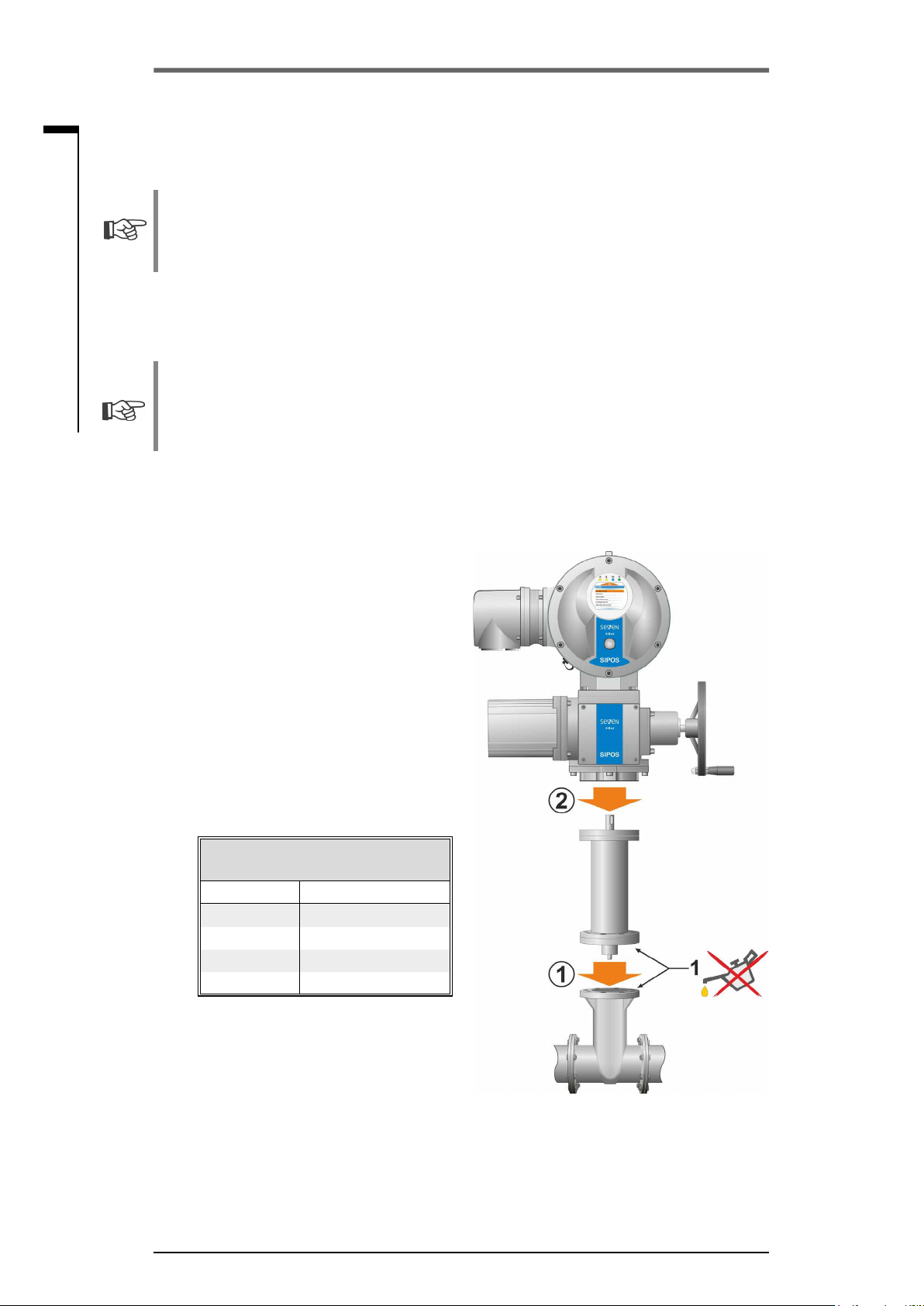
How to proceed
1. Thoroughly clean and degrease contact
surfaces at linear thrust unit and valve (g.,
pos. 1).
2. Place linear thrust unit ensuring that bores of
output mounting ange align perfectly with
the threaded bores of the valve ange.
Ensure that the spigot mates uniformly and
that the mounting faces are in complete
contact.
3. Fasten linear thrust unit with screws (strength
class min. 8.8):
– We recommend applying liquid thread
sealing material to the screws to avoid
contact corrosion.
– Fasten screws crosswise applying the
required tightening torque according to
the table below:
Tightening torques for screws of
tightening class 8�8
Threads Tightening torque
M8 25 Nm
M10 51 Nm
M16 214 Nm
M20 341 Nm
4. Connect thrust rod using a coupling to the valve
stem.
The type of connection depends on the
valve and is determined by the valve manu-
facturer
Fig�: Mounting linear thrust unit
Y070.518/EN Page 5
Supplement to operation instructions SIPOS SEVEN
2SL78 linear thrust unit
2
Mounting linear thrust unit
2 Mounting linear thrust unit
2�2 Mounting to actuator
2�2 Mounting actuator to linear thrust unit
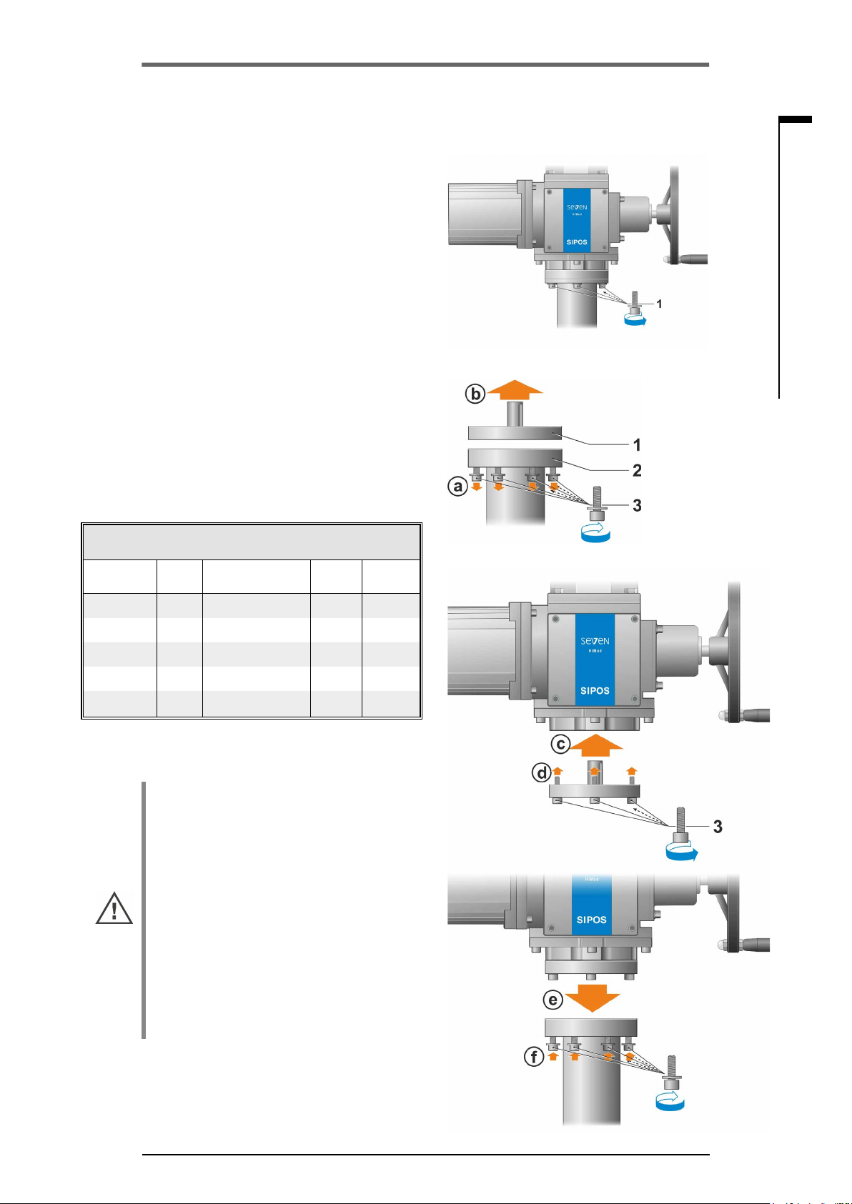
How to proceed
1. Clean contact surfaces of actuator and linear thrust
unit.
2. Assembly may dier depending on the actuator:
For 2SL781/2 actuator:
a) Place actuator on linear thrust unit and
slightly tighten using the provided screw with
washers (g. 1, pos. 1).
b) Fasten screws evenly crosswise while re-
specting the torque, refer to table below:
For 2SL783/4/5 actuator:
a) Unscrew ange (g. 2, pos. 1) from linear
thrust unit (pos. 2).
b) Fasten ange to actuator.
c) Fasten ange to actuator (g. 3).
d) Place actuator on linear thrust unit (g. 4)
and slightly tighten using the screws with
washers.
e) Fasten screws evenly crosswise while re-
specting the torque, refer to table below:
Tightening torques when combining
actuator and linear thrust unit
Linear thrust
unit Flange Screws 8.8 Dented
washers Torque
2SL781 F10 DIN 912-M10x30 S 10 40 Nm
2SL782 F10 DIN 912-M10x30 S 10 40 Nm
2SL783 F14 DIN 7984-M16x30 S 16 170 Nm
2SL784 F14 DIN 7984-M16x35 S 16 170 Nm
2SL785 F16 DIN 7984-M20x40 S 30 340 Nm
2�3 Stroke limitation
■With linear thrust units, stroke is limited by
end stops. These end stops may not be
approached in motor operation. Not even as
stroke limitation for torque tripping. This could
lead to linear thrust unit damage.
■The mechanical end stops of linear thrust
units are not required when operating the de-
vice in standard operation mode. They serve
the purpose as “second protection” against
manual operation beyond the desired setting
range.
■In the factory, the mechanical end stops are
adapted to the dened maximum stroke of
linear thrust units. Changing this maximum
stroke is not possible (refer to subsequent
chapter, item 2.).
Fig. 2: Unscrew ange from linear thrust unit
Fig. 3: Screw ange to actuator
Fig. 4: Screw ange to linear thrust unit
Fig� 1: Mounting actuator to linear thrust unit

Supplement to operation instructions SIPOS SEVEN
2SL78 linear thrust unit
Page 6 Y070.518/EN
3 Maintenance
3
Maintenance
2�4 End position setting and test run
End position setting at actuator must be performed, refer to operation instructions SEVEN, chapter
“Commissioning”.
1. Check direction of operation:
a) Operate the linear thrust unit in middle position in manual operation mode.
b) Briey operate the actuator in direction OPEN. If the direction of operation is incorrect, imme-
diately stop and change the direction of operation. For this, refer to the actuator operation
instructions, chapter “Commissioning”.
2. Operate in direction CLOSE in motor operation. Prior to reaching the end position, continue
operation in manual mode until torque rises. Then check, if
– either the position of the valve
or
– the mechanical end stop of linear thrust unit is reached.
If the mechanical end stop of the linear thrust unit is reached prior to the valve reaching the end
position, replace the linear thrust unit selecting a device oering a larger stroke ranges.
3 Maintenance
3�1 General notes
After commissioning, check the linear thrust unit for damage to paint nish. To avoid damage by
corrosion, thoroughly touch up damage to paint nish.
Basically, the linear thrust unit does not require maintenance. However, to ensure continuous avail-
ability, we recommend the following actions:
■Approximately six months after commissioning and every year after, check bolts of linear thrust
unit to multi-turn actuator and to valve for tightness. If required, fasten screws applying the
appropriate torques corresponding to the tightening class of the screws applied (refer to table in
chapter 2.1).
■Perform a visual inspection once a year for oil and grease leakage. In case of leakage, replace
linear thrust unit.
■Perform a detailed functional test of the linear thrust unit every 2 years.
■Linear thrust unit permanently subjected to temperatures over 40 °C must be serviced in shorter
intervals.
3�2 Seals
Seals made of elastomer are subject to ageing. We recommend to replace the seals of linear thrust
units after 8 years during actuator revision.
3�3 Oil change
We recommend an oil change for linear thrust units after 8 years. In case of frequent operation or
modulating duty, the recommended period is every 4 to 8 years. In case of infrequent operation, the
period is recommended at 10 to 12 years.
■Exclusively use original oil or an approved equivalent. Indications to oil quantities are indicated
in the table below.
■We recommend a lubricating oil CLP 220 (DIN 51517 Part 3), e.g. BECHEM Staroil G220 by
CARL BECHEM GmbH.
■Removed lubricants and used cleaning agents must be disposed of complying with the valid
regulations.
Oil quantities for linear thrust unit
Linear thrust unit Stroke 100 mm Stroke 300 mm
2SL781, 2SL782 0.3 l 0.6 l
2SL783 075 l 1.35 l
2SL784, 2SL785 1,1 Liter 2.0 l
Issue 07.20 Y070.518/EN
Subject to changes without notice!
© SIPOS Aktorik GmbH
Im Erlet 2 • 90518 Altdorf/Germany
www.sipos.de
This manual suits for next models
5
Table of contents


