SIRETTA ZOOM-EVK User manual
inspired wireless technology
ZOOM-EVK
User Manual
Rev 1.9

2
A member of the Olancha Group Ltd
Registered in England No. 08405712
VAT Registration No. GB163 04 0349
Siretta Ltd
Basingstoke Road
Spencers Wood
Reading
Berkshire RG7 1PW
sales
fax
email
web
+44(0)118 976 9014
+44(0)118 976 9020
www.siretta.co.uk
inspired wireless technology ZOOM-EVK
User Manual
Table of Contents
Page
Introduction 3
About Siretta 4
ZOOM-EVK 5
ZOOM Board Headers 7
EVK Board Connectors 8
GPIO Board Connectors 10
Standard Board Jumpers 12
GPIO Board Jumpers 13
Default Conguration 14
In System Debug 15
USB-RS232-TTL Cable to ZOOM Header
Connection
15
Disclaimer 16
Denitions 17

3
A member of the Olancha Group Ltd
Registered in England No. 08405712
VAT Registration No. GB163 04 0349
Siretta Ltd
Basingstoke Road
Spencers Wood
Reading
Berkshire RG7 1PW
sales
fax
email
web
+44(0)118 976 9014
+44(0)118 976 9020
www.siretta.co.uk
inspired wireless technology ZOOM-EVK
User Manual
This document is intended to provide guidance when adding the ZOOM-EVK to your
system. The ZOOM-EVK is an evaluation platform used to evaluate the ZOOM series
embedded socket modems.
This document discusses the layout and functions of the ZOOM-EVK.
Introduction

4
A member of the Olancha Group Ltd
Registered in England No. 08405712
VAT Registration No. GB163 04 0349
Siretta Ltd
Basingstoke Road
Spencers Wood
Reading
Berkshire RG7 1PW
sales
fax
email
web
+44(0)118 976 9014
+44(0)118 976 9020
www.siretta.co.uk
inspired wireless technology ZOOM-EVK
User Manual
Siretta, located in Reading, United Kingdom have been manufacturing antennas,
cable assemblies and cellular terminals for over 10 years. We supply our products
globally to many of the world’s leading organisations.
Whether you require an off the shelf or custom solution, Siretta has a wide portfolio of
antenna, RF cable assemblies and terminals to t your application.
Our extensive knowledge and experience in the wireless market allows us to support
a wide range of customer applications, focusing on frequencies typically within the
75MHz - 5.8GHz range. These encompass the HF, VHF, ISM, GSM/GPRS/3G/4G
and GPS frequencies as well as industrial WLAN and VHF/UHF antenna/Wi-Fi
antenna solutions.
With a heavy emphasis on design, we have a team of dedicated Application
Engineers and Product Managers, backed up by Field Sales Engineers, who
specialise in wireless applications.
We have made signicant investments in R&D facilities which boast GPS hardware
development equipment and a GSM Pico Cell on site, as well as development
software and a comprehensive suite of Industrial, Scientic and Medical band, and
non ISM band frequency products. We have many technology partners enabling us to
keep at the forefront of the communications industry and offer class leading wireless
solutions.
About Siretta

5
A member of the Olancha Group Ltd
Registered in England No. 08405712
VAT Registration No. GB163 04 0349
Siretta Ltd
Basingstoke Road
Spencers Wood
Reading
Berkshire RG7 1PW
sales
fax
email
web
+44(0)118 976 9014
+44(0)118 976 9020
www.siretta.co.uk
inspired wireless technology ZOOM-EVK
User Manual
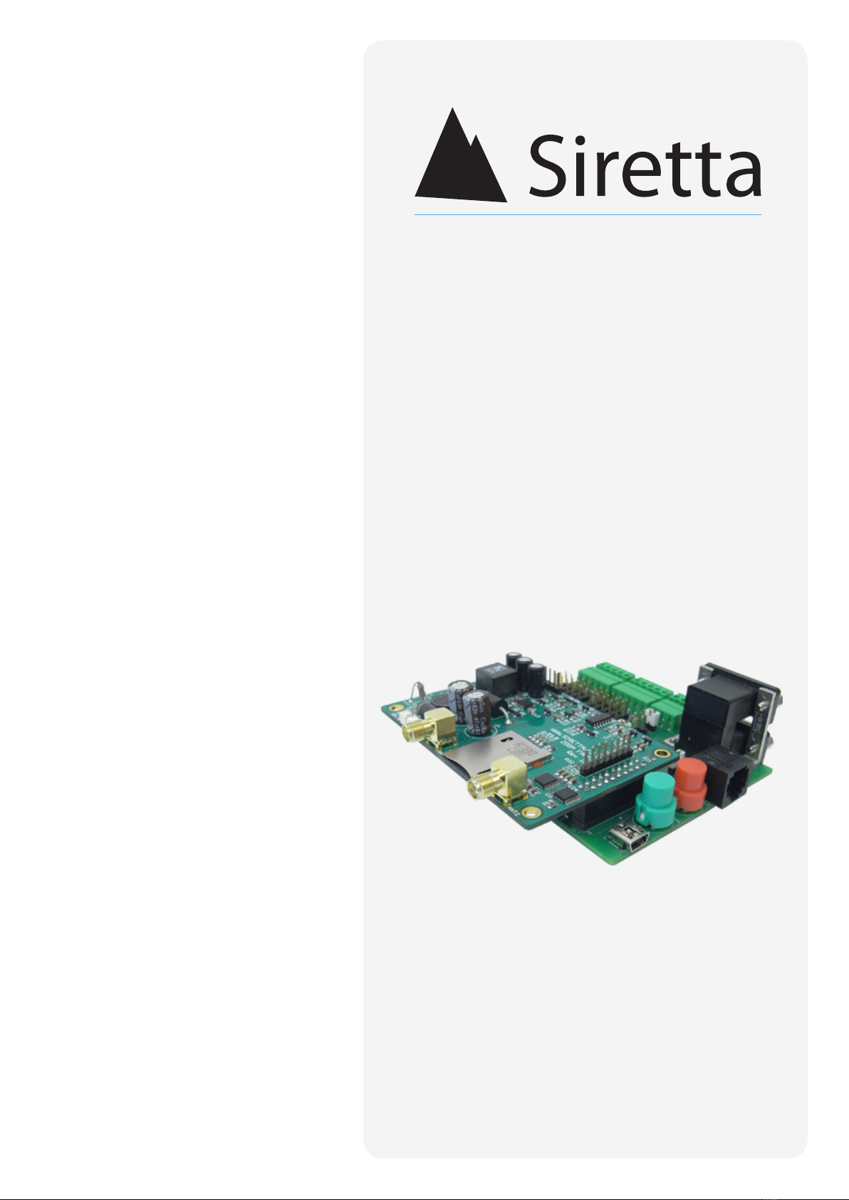
ZOOM-EVK
Embedded Socket Modem Evaluation Platform
Figure 1. ZOOM-EVK
The ZOOM-EVK is an evaluation platform to easily evaluate the ZOOM Series of
embedded socket modems. The EVK gives you access to all of the ZOOM modems
functionality including the following:
»RS232 AT command port
»RS232 debug port
»USB serial port
»4 x GPI
»4 x GPO
»2 x GPO (Optional GPI)
»1 x ADC
»RTC power
»Autopower on
»Manual power on/power off
6
A member of the Olancha Group Ltd
Registered in England No. 08405712
VAT Registration No. GB163 04 0349
Siretta Ltd
Basingstoke Road
Spencers Wood
Reading
Berkshire RG7 1PW
sales
fax
email
web
+44(0)118 976 9014
+44(0)118 976 9020
www.siretta.co.uk
inspired wireless technology ZOOM-EVK
User Manual
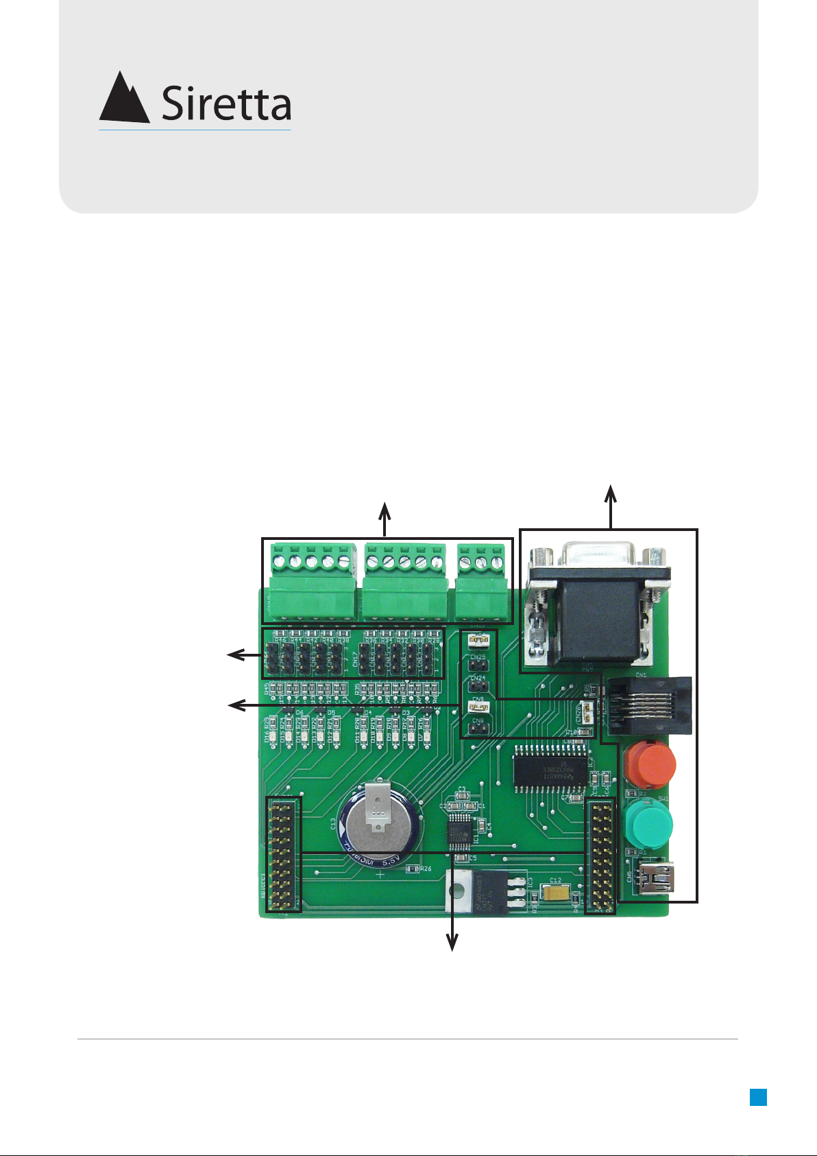
Below, gure 2 shows the EVK layout and descriptions for each of the sections is
explained in more detail. The board is split into the following sections:
»ZOOM Board Headers
»EVK Board Connectors
»GPIO Board Connectors
»Standard Board Jumpers
»GPIO Board Jumpers
Figure 2. ZOOM-EVK layout
GPIO Board Connectors
EVK Board Connectors
Standard Board Jumpers
GPIO Board Jumpers
ZOOM Board Headers
7
A member of the Olancha Group Ltd
Registered in England No. 08405712
VAT Registration No. GB163 04 0349
Siretta Ltd
Basingstoke Road
Spencers Wood
Reading
Berkshire RG7 1PW
sales
fax
email
web
+44(0)118 976 9014
+44(0)118 976 9020
www.siretta.co.uk
inspired wireless technology ZOOM-EVK
User Manual
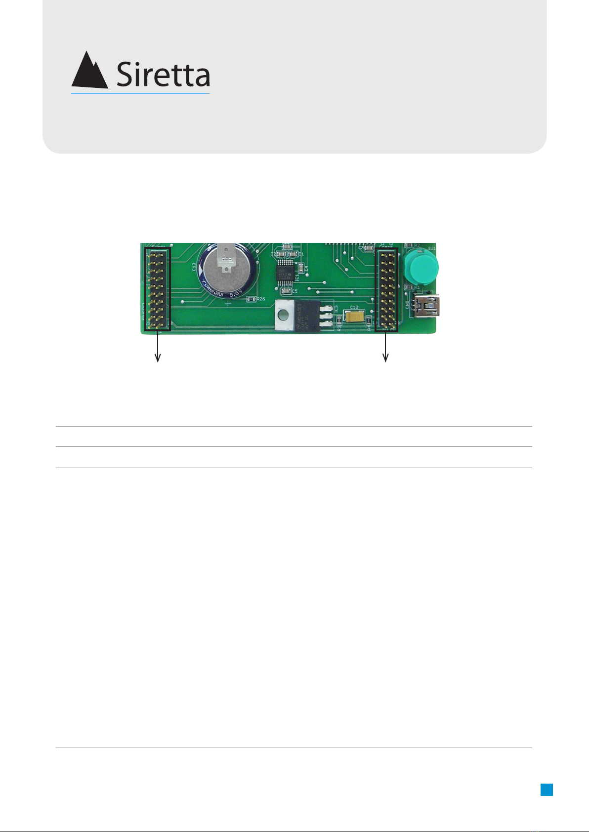
ZOOM Board Headers
Figure 3. ZOOM Board Headers
12
No. Item Description
1Function Header Used to connect the ZOOM modem to the ZOOM-EVK
2Communication Header Used to connect the ZOOM modem to the ZOOM-EVK
8
A member of the Olancha Group Ltd
Registered in England No. 08405712
VAT Registration No. GB163 04 0349
Siretta Ltd
Basingstoke Road
Spencers Wood
Reading
Berkshire RG7 1PW
sales
fax
email
web
+44(0)118 976 9014
+44(0)118 976 9020
www.siretta.co.uk
inspired wireless technology ZOOM-EVK
User Manual
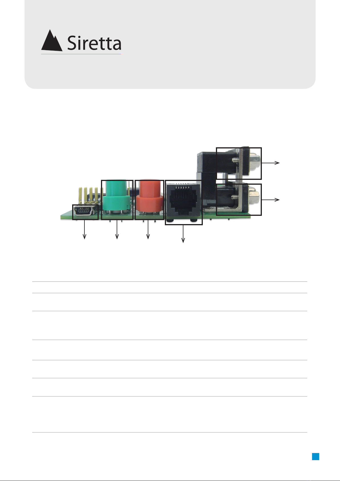
EVK Board Connectors
Figure 4. EVK Board Connectors
14
No. Item Description
1Modem USB connection Used to communicate with the modem via USB serial cable
2Power ON/OFF switch Used to switch the modem ON/OFF when CN9 (auto power on)
is not connected
3Hardware RESET switch Used to reset the modem when it has stopped responding.
DO NOT use to power off the modem, only use as a disaster
recovery option
412V power input Used to power the board from a standard RJ12 power supply
(See ‘Power Supply Requirements’ on page 9)
5RS232 AT command port Used to control modem and send AT commands to congure
the modem settings
6RS232 Debug / Trace Port Used to communicate with the modem to enable Trace Client
diagnostics and Python debug output
2 3
5
6
9
A member of the Olancha Group Ltd
Registered in England No. 08405712
VAT Registration No. GB163 04 0349
Siretta Ltd
Basingstoke Road
Spencers Wood
Reading
Berkshire RG7 1PW
sales
fax
email
web
+44(0)118 976 9014
+44(0)118 976 9020
www.siretta.co.uk
inspired wireless technology ZOOM-EVK
User Manual
Power Supply Requirements
The DC power supply must be connected to the power input.
Table 1. Characteristics of power inputs
The module is supplied with a 12V mains adaptor. It can also be powered from an
alternative power source with a voltage range, as shown in table 1 above.
Input power protection :
»On board voltage reverse polarity protection
»Overvoltage spike protection to 70V for 1mS.
»ESD protection to +/-4KV contact discharge and +/-8KV air discharge.
ZOOM-EVK
Input voltage 5 to 42V
Recommended input voltage 12V DC
Supply current:
Peak (20ms at registration) 2A
Average standby 25mA
Call in progress 250mA
Ringing 250mA
PIN PIN Name Pin Description ZOOM-EVK
1POWER +Vcc ZOOM POWER Vcc (12V nominal)
2N/C Not connected
3N/C Not connected
4N/C Not connected
5N/C Not connected
6GND ZOOM GND Common GND connection (0v)
Table 2. Power connector pin functions
Figure 5. Power connector
Pin 1 Pin 6

10
A member of the Olancha Group Ltd
Registered in England No. 08405712
VAT Registration No. GB163 04 0349
Siretta Ltd
Basingstoke Road
Spencers Wood
Reading
Berkshire RG7 1PW
sales
fax
email
web
+44(0)118 976 9014
+44(0)118 976 9020
www.siretta.co.uk
inspired wireless technology ZOOM-EVK
User Manual
GPIO Board Connectors
Figure 6. GPIO Board Connectors
1 2 3
No. Item Description
1GPI5 Input, GPI6 Input, GPI7 Input,
GPO8 Output, GPO9 Output
Used to connect external devices to the modem to read an
input or set an output
2GPO0 Output, GPO1 Output,
GPO2 Output, GPO3 Output, GPI4
Input
Used to connect external devices to the modem to read an
input or set an output
3GPIO power supply and ADC input Used to power external voltage sources for GPI inputs and
provide GND reference. ADC input to read external anaglogue
voltage from the modem.
AB C D E FGHIJ K L M
Letter PIN Description Direction
A Pin 1 GPO6 Output
BPin 2 GPO5 Output
CPin 3 GPI4 Input
DPin 4 GPI3 Input
EPin 5 GPI2 Input
Connector 1
Letter PIN Description Direction
KPin 1 3.3V Output
LPin 2 GND Output
MPin 3 ADC1 Inputl
Connector 3
Letter PIN Description Direction
F Pin 1 GPI1 Input
GPin 2 GPO4 Output
HPin 3 GPO3 Output
IPin 4 GPO2 Output
JPin 5 GPO1 Output
Connector 2
11
A member of the Olancha Group Ltd
Registered in England No. 08405712
VAT Registration No. GB163 04 0349
Siretta Ltd
Basingstoke Road
Spencers Wood
Reading
Berkshire RG7 1PW
sales
fax
email
web
+44(0)118 976 9014
+44(0)118 976 9020
www.siretta.co.uk
inspired wireless technology ZOOM-EVK
User Manual
Signal Name Parameter Minimum Nominal Maximum
GPI 1-4 Input high level 1.65V 3.3V 3.6V
GPI 1-4 Input low level 0V 0V 0.5V
GPO 1-6 Output high level 1.65V 3.3V 3.6V
GPO 1-6 Output low level 0V 0V 0.5V
Table 3. GPIO minimum/maximum voltage for ZOOM-EVK

12
A member of the Olancha Group Ltd
Registered in England No. 08405712
VAT Registration No. GB163 04 0349
Siretta Ltd
Basingstoke Road
Spencers Wood
Reading
Berkshire RG7 1PW
sales
fax
email
web
+44(0)118 976 9014
+44(0)118 976 9020
www.siretta.co.uk
inspired wireless technology ZOOM-EVK
User Manual
Standard Board Jumpers
Figure 7. Standard Board Jumpers
1
2
3
4
5
6
No. Item Description
1 GPIO1 to red status LED Used to display GSM network registration status when GPIO1 is
used in alternate function mode
AT#GPIO=1,0,2
AT#SLED=3
AT#SLEDAV
2 GPIO3 to blue status LED Congure GPIO3 to turn blue status LED on and off
3GPIO2 to green status LED Congure GPIO2 to turn green status LED on and off
4Auto power on mode connection Modem will power up automatically when main power is applied
5VRTC enable pin to VRTC battery
connection
Used to provide power for the RTC when main power is re-
moved
6Vin to main power board
connection
Used to measure board current usage*
*Note: To measure the drawn current current on the board, remove the jumper and connect an ammeter to the jumper pins.

13
A member of the Olancha Group Ltd
Registered in England No. 08405712
VAT Registration No. GB163 04 0349
Siretta Ltd
Basingstoke Road
Spencers Wood
Reading
Berkshire RG7 1PW
sales
fax
email
web
+44(0)118 976 9014
+44(0)118 976 9020
www.siretta.co.uk
inspired wireless technology ZOOM-EVK
User Manual
GPIO Board Jumpers
Figure 8. GPIO Board Jumpers
1 2 3 4 5 6 7 8 910
No. Item Description
1GPIO10 jumper Not used for GPIO function
2GPIO9 jumper Not used for GPIO function
3GPIO8 jumper Used to manually set GPIO to logic 1 or logic 0
4GPIO7 jumper Used to manually set GPIO to logic 1 or logic 0
5GPIO6 jumper Used to manually set GPIO to logic 1 or logic 0
6GPIO5 jumper Used to manually set GPIO to logic 1 or logic 0
7GPIO4 jumper Not used for GPIO function
8GPIO3 jumper Not used for GPIO function
9 GPIO2 jumper Not used for GPIO function
10 GPIO1 jumper Not used for GPIO function
3.3V
To Module
GND

14
A member of the Olancha Group Ltd
Registered in England No. 08405712
VAT Registration No. GB163 04 0349
Siretta Ltd
Basingstoke Road
Spencers Wood
Reading
Berkshire RG7 1PW
sales
fax
email
web
+44(0)118 976 9014
+44(0)118 976 9020
www.siretta.co.uk
inspired wireless technology ZOOM-EVK
User Manual
Default Conguration
Figure 9. Default Conguration
Use the following conguration setup to get started with the ZOOM evaluation platform.
The following jumpers are used to implement the following functions:
»Connect Vin power to the main power supply to power the main board
»Connect the GSM registration status to the red LED to display network registration
»Connect auto power on jumper to auto power up the modem when power is applied.
1
3
2
No. Item Description
1 GPIO1 to red status LED
connection
Used to display GSM network registration status when GPIO1 is
used in alternate function mode
AT#GPIO=1,0,2
AT#SLED=2
AT#SLEDSAV
2Auto power on mode connection Modem will power up automatically when main power is applied
3Vin to main board power
connection
Used to measure current usage on board or directly power the
board when jumper is tted
15
A member of the Olancha Group Ltd
Registered in England No. 08405712
VAT Registration No. GB163 04 0349
Siretta Ltd
Basingstoke Road
Spencers Wood
Reading
Berkshire RG7 1PW
sales
fax
email
web
+44(0)118 976 9014
+44(0)118 976 9020
www.siretta.co.uk
inspired wireless technology ZOOM-EVK
User Manual
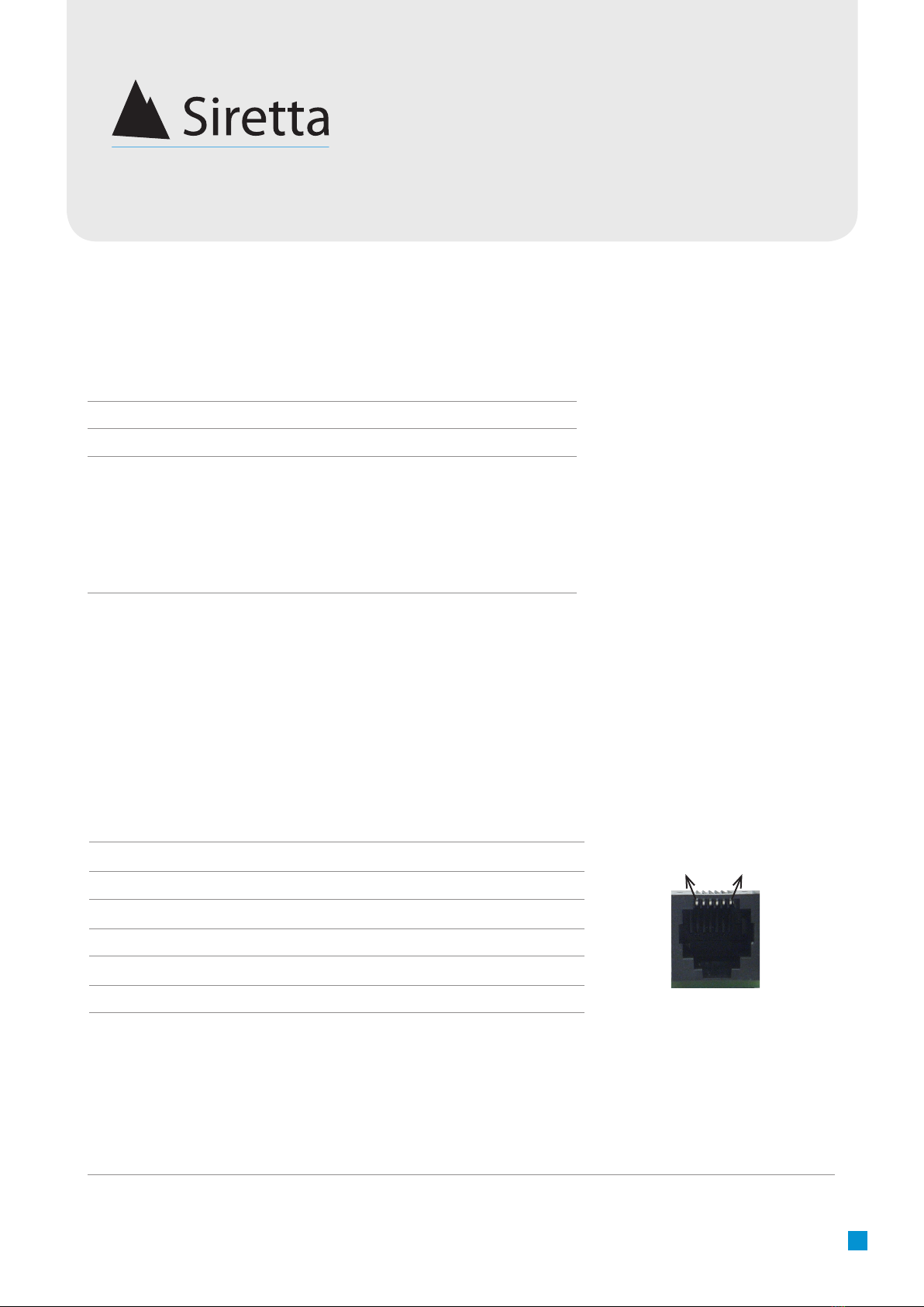
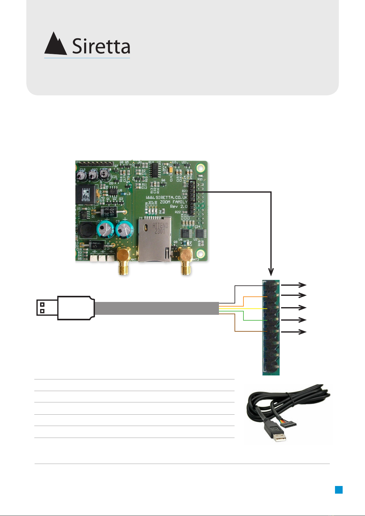
In System Debug
Buy USB-RS232-TTL cable from:
http://www.ftdichip.com/Products/Cables/USBTTLSerial.htm
Please note: cable pins will need removing from connector in order to wire the
cable to the ZOOM module correctly.
Pin 1
Pin 5
Pin 4
Pin 3
Pin 2
ZOOM Header Pin No. Cable Pin No./Colour RS232 Pin Out
11/Black GND
24/Orange TX
35/Yellow RX
46/Green RTS
52/Brown CTS
USB-RS232-TTL Cable to ZOOM Header Connection
Figure 11. USB-RS232-TTL Cable
Pin 1
Pin 2
Pin 4
Pin 5
Pin 6
Figure 10. ZOOM header connection

16
A member of the Olancha Group Ltd
Registered in England No. 08405712
VAT Registration No. GB163 04 0349
Siretta Ltd
Basingstoke Road
Spencers Wood
Reading
Berkshire RG7 1PW
sales
fax
email
web
+44(0)118 976 9014
+44(0)118 976 9020
www.siretta.co.uk
inspired wireless technology ZOOM-EVK
User Manual
The information contained in this document is proprietary to Siretta Ltd. Siretta
has made every effort to ensure that the accuracy of the information contained
within this document is accurate. Siretta does not make any warranty as to the
information contained within this document and does not accept any liability for
any injury, loss or damage of any kind incurred by the use of this information.
Siretta does not take responsibility for any application developed using the device
characterized in this document and notes that any application of this device
must comply with the safety standards of the applicable country and comply
with the relevant wiring rules. Siretta reserves the right to make modications,
additions and deletions to this document due to typographical errors, inaccurate
information, or improvements to equipment at any time and without notice. Such
changes will be incorporated into new editions of this document.
All rights reserved.
© 2014 Siretta Ltd
Disclaimer
17
A member of the Olancha Group Ltd
Registered in England No. 08405712
VAT Registration No. GB163 04 0349
Siretta Ltd
Basingstoke Road
Spencers Wood
Reading
Berkshire RG7 1PW
sales
fax
email
web
+44(0)118 976 9014
+44(0)118 976 9020
www.siretta.co.uk
inspired wireless technology ZOOM-EVK
User Manual
Denitions
Term Denition
3G 3rd Generation Mobile Telecommunications
ADC Analog to Digital Converter
CAN Controller Area Network
CDMA Code Division Mutiple Access
DAC Digital to Analog Converter
ESD Electro-Static Discharge
GPI General Purpose Input
GPIO General Purpose Input Output
GPO General Purpose Output
GPRS General Packet Radio Service
GPS Global Positioning System
GSM Global System for Mobile Communications
I2C Multimaster serial single-ended computer bus
I/O Input/Output
JTAG Joint Test Action Group
LED Light Emitting Diode
LTE Long Term Evolution
RS232 Recommended Standard 232 - binary serial communications
Sequoia Sequoia Technology Group Ltd
SIM Subscriber Identity Module
SMA Sub Miniature version A
STMF32F4 Microcontroller Family
TTL Transistor-Transistor Logic
UART Universal Asynchronous Receiver/Transmitter
UMTS Universal Mobile Telecommunications System (Same as 3G)
USB Universal Serial Bus
VSWR Voltage Standing Wave Ratio

Siretta is currently growing its worldwide distributor and reseller base. Distributors can
benefi t from an excellent product range, marketing and technical support, along with
the widest range of Antennas, Connectors, Cable Assemblies and Wireless Terminals.
Siretta Ltd
Basingstoke Road
Spencers Wood
Reading
Berkshire
RG7 1PW
United Kingdom
sales
fax
accounts
email
Company No. 08405712
VAT Registration No. GB163 04 0349
A member of the Olancha Group Ltd
+44 (0)118 976 9014
+44 (0)118 976 9020
+44 (0)118 976 9069
www.siretta.co.uk
Become A Distributor
inspired wireless technology
Rev 1.9 - Oct 2014
Table of contents


