Socket MS8158D Series User manual

This publication, including all photographs, illustrations and
software, is protected under international copyright laws, with all
rights reserved. Neither this manual, nor any of the material
contained herein, may be reproduced without the express written
consent of the manufacturer.
The information in this document is subject to change without
notice. The manufacturer makes no representations or warranties
with respect to the contents hereof and specifically disclaims any
implied warranties of merchantability or fitness for any particular
purpose. Further, the manufacturer reserves the right to revise this
publication and to make changes from time to time in the content
hereof without obligation of the manufacturer to notify any person
of such revision or changes.
Trademarks
IBM, VGA, and PS/2 are registered trademarks of International
Business Machines.
AMD, Duron and Athlon are registered trademarks of Advanced
Micro Devices Inc.
Microsoft, MS-DOS and Windows 98/ME/NT/2000/XP are
registered trademarks of Microsoft Corporation.
PC-cillin is a registered trademark of Trend Micro Inc.
AMI is a registered trademark of American Megatrends Inc.
Other names used in this publication may be trademarks and are
acknowledged.
Copyright © 2003
All Rights Reserved
MS8158D Series, V7.2A
VKM266/December 2003
II
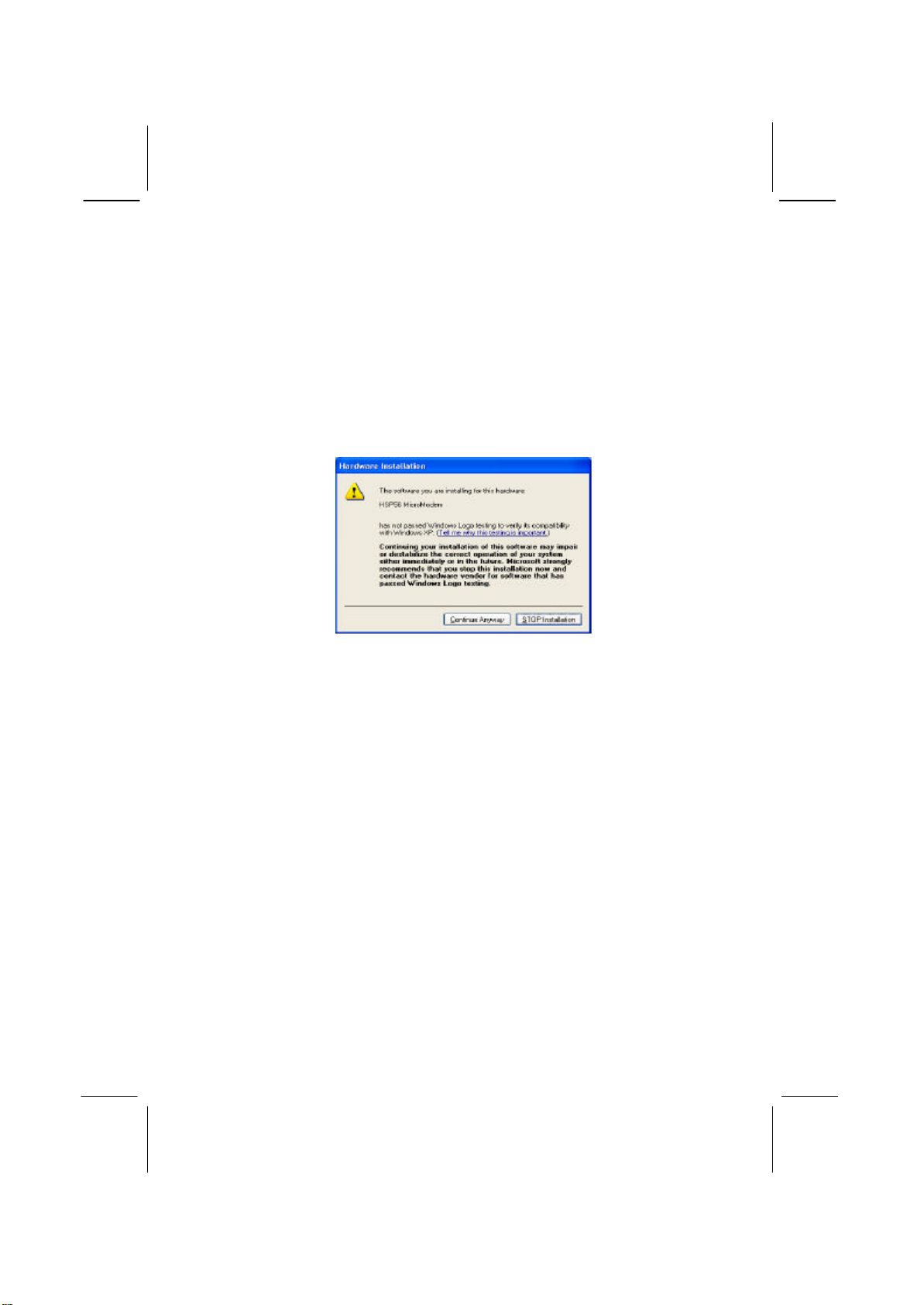
Notice:
1. Owing to Microsoft’s certifying schedule is various to every
supplier, we might have some drivers not certified yet by
Microsoft. Therefore, it might happen under Windows XP that a
dialogue box (shown as below) pop out warning you this
software has not passed Windows Logo testing to verify its
compatibility with Windows XP. Please rest assured that our RD
department has already tested and verified these drivers. Click
the “Continue Anyway” button and go ahead the installation.
2. USB 2.0 Driver Limitations:
2-1 The USB 2.0 driver only supports Windows XP and
Windows 2000.
2-2 If you connect a USB 2.0 hub to the root hub, plugging USB
devices into this hub, the system might not successfully
execute certain USB devices’connection because it could not
recognize these devices.

III
Table of Contents
Trademarks........................................................................ I
Chapter 1: Introduction..............................................................1
Key Features......................................................................2
Package Contents...............................................................5
Static Electricity Precautions...............................................6
Pre-Installation Inspection...................................................6
Chapter 2: Mainboard Installation...............................................7
Mainboard Components......................................................8
I/O Ports............................................................................8
Installing the Processor.......................................................9
Install Memory Modules...................................................10
Jumper Settings ................................................................11
Install the Mainboard........................................................12
Connecting Optional Devices............................................13
Install Other Devices........................................................16
Expansion Slots................................................................18
Chapter 3: BIOS Setup Utility..................................................19
Introduction.....................................................................19
Running the Setup Utility..................................................20
Standard CMOS Setup Page.............................................. 21
Advanced Setup Page.......................................................22
Power Management Setup Page.........................................24
PCI / Plug and Play Setup Page .........................................26
Load Optimal Settings ...................................................... 27
Load Best Performance Settings ........................................27
Features Setup Page..........................................................27
CPU PnP Setup Page ........................................................29
Hardware Monitor Page....................................................30
Change Password.............................................................30
Exit .................................................................................31
Chapter 4: Software & Applications ..........................................32
About the Software & CD-ROM.......................................32
Utility Software Reference................................................33

IV

Chapter 1
Introduction
This mainboard has a Socket-A support for the AMD K7
processors. The Socket-A processor’s front-side bus speed is
266MHz.
This mainboard has aKM266 chipset that supports one 4X AGP
slot for highly graphics display, 100/133 MHz DDR, and Ultra
DMA ATA100/133 function to provide outstanding high system
performance under all types of system operations. It supports the
built-in AC97 Codec, and the 128-bit 2D/3D AGP Graphics
Acceleratorwith 32MB frame buffer, supporting AGP 4X
266MHz mode up to 1GB/s bandwidth, which provides a direct
connection between the graphics sub-system and memory so that
the graphics do not have to compete for processor time with other
devices on the PCI bus. There is a full set of I/O Ports including
PS/2 keyboard and mouse ports, one serial port, one onboard VGA
port, one parallel port, and maximum six USB2.0 ports –four
back-panel ports and onboard USB header USB3 providing two
extra ports by connecting the Extended USB Module to the
mainboard.
This mainboard has all the features you need to develop a powerful
multimedia workstation that is network ready. The board is Micro
ATX size and has power connectors for an ATX power supply.

2
Key Features
The key features of this mainboard include:
Socket-A Processor Support
♦Supports AMD Athlon XP/Athlon/Duron processors
♦Supports 266 MHz Front-Side Bus
Chipset
There are VIA KM266 Northbridge and VT8235 Southbridge in
this chipset in accordance with an innovative and scalable
architecture with proven reliability and performance. A few of the
chipset’s advanced features are:
♦An advanced V-Link memory controller architecture that
provides the bandwidth up to 266 MB/s and performance
necessary for even the most demanding Internet and
2D/3D graphics
♦Support for an 4xAGP interface providing vivid 2D/3D
graphics and video performance
Memory Support
♦Two 184-pin DIMM slots for DDR memory modules
♦Support for 100/133 MHz memory bus
♦Maximum installed memory is 2GB
Expansion Slots
♦One 4X AGP slot for AGP 2.0-compliant interface
♦Two 32-bit PCI slots for PCI 2.2-compliant bus interface
Onboard IDE channels
♦Primary and Secondary PCI IDE channels
♦Support for PIO (programmable input/output) modes
♦Support for Multiword DMA modes
♦Support for Bus Mastering and Ultra DMA ATA
33/66/100/133modes

3
Power Supply and Power Management
♦ATX power supply connector
♦ACPI and previous PMU support, suspend switch,
keyboard power on/off
VGA
♦Single cycle 128-bit 3D architecture
♦128-bit 2D graphic engine
♦8/16/32 MB frame buffer using system memory
♦Supports AGP 4X 266 MHz mode up to 1GB/s bandwidth
♦Supports 250MHz RAMDAC
♦2D/3D resolutions up to 1920x1440
♦Supports AGP Rev. 2.0 Spec. Compliant
AC97 Codec
♦Compliant with AC’97 2.1 specification
♦16-bit stereo full-duplex CODEC with fixed 48KHz
sampling rate
♦3 analog line-level stereo inputs with 5-bit volume control:
LINE-IN, CD-IN
♦Three Audio Jacks–Line-Out, Line-In and Microphone-In
♦Sound Blaster, Sound Blaster Pro Compatible
♦Advanced power management support
Onboard I/O Ports
♦Provides PC99 Color Connectors for easy peripheral device
connections
♦Floppy disk drive connector with 1Mb/s transfer rate
♦Two PS/2 ports for keyboard and mouse
♦One serial port with 16C550-compatible fast UART
♦One parallel port with ECP and EPP support
♦One VGA port
♦Four back-panel USB2.0 ports and extra two USB2.0 ports
(onboard USB header USB3)

4
USB 2.0
♦Compliant with Universal Serial Bus Specification
Revision 2.0
♦Compliant with Intel’s Enhanced Host Controller
Interface Specification Revision 0.95
♦Compliant with Universal Host Controller Interface
Specification Revision 1.1
♦PCI multi-function device consists of two UHCI Host
Controllercores for full-/low-speed signaling and one
EHCI Host Controllercore for high-speed signaling
♦Root hub consists 4 downstream facing ports with
integrated physical layer transceivers shared by UHCI and
EHCIHost Controller
♦Support PCI-Bus Power Management Interface
Specification release 1.1
♦Legacy support for all downstream facing ports
Hardware Monitoring
♦Built-in hardware monitoring for CPU & System
temperatures, fan speeds and mainboard voltages
Onboard Flash ROM
♦Supports Plug and Play configuration of peripheral devices
and expansion cards
Bundled Software
♦PC-Cillin2002 provides automatic virus protection under
Windows 98/ME/NT/2000/XP
♦Adobe Acrobat Reader V5.0 is the software to help users
read .PDF files.
Dimensions
♦Micro ATX form factor (24.4cm x 19cm)
Note: Hardware specifications and software items are
subject to change without notification.

5
Package Contents
Your mainboard package ships with the following items:
qThe mainboard
qThe User’s Manual
qOne diskette drive ribbon cable (optional)
qOne IDE drive ribbon cable
qSoftware support CD
Optional Accessories
You can purchase the following optional accessories for this
mainboard.
qExtended USB module
qCard Reader (You can buy your own Card Reader from the
third party, but please contact your local Card Reader vendor
on any issues of the specification and compatibility.)
Note: You can purchase your own optional accessories from the
third party, but please contact your local vendor on any
issues of the specification and compatibility

Static Electricity Precautions
Components on this mainboard can be damaged by static
electricity. Take the following precautions when unpacking the
mainboard and installing it in a system.
1. Keep the mainboard and other components in their original
static-proof packaging until you are ready to install them.
2. During installation, wear a grounded wrist strap if possible. If
you don’t have a wrist strap, discharge static electricity by
touching the bare metal of the system chassis.
3. Handle the mainboard carefully by the edges. Avoid touching
the components unless it is absolutely necessary. During
installation put the mainboard on top of the static-protection
packaging it came in with the component side facing up.
Pre-Installation Inspection
1. Inspect the mainboard for damage to the components and
connectors on the board.
2. If you suspect that the mainboard has been damaged, do not
connect power to the system. Contact your mainboard vendor
and report the damage.

Chapter 2
Mainboard Installation
To install this mainboard in a system, please follow these
instructions in this chapter:
qIdentify the mainboard components
qInstall a CPU
qInstall one or more system memory modules
qMake sure all jumpers and switches are set correctly
qInstall this mainboard in a system chassis (case)
qConnect any extension brackets or cables to connecting
headers on the mainboard
qInstall other devices and make the appropriate connections to
the mainboard connecting headers
Note:
1. Before installing this mainboard, make sure jumper JP2 is
under Normal setting. See this chapter for information about
locating JP2 and the setting options.
2. Never connect power to the system during installation;
otherwise, it may damage the mainboard.

8
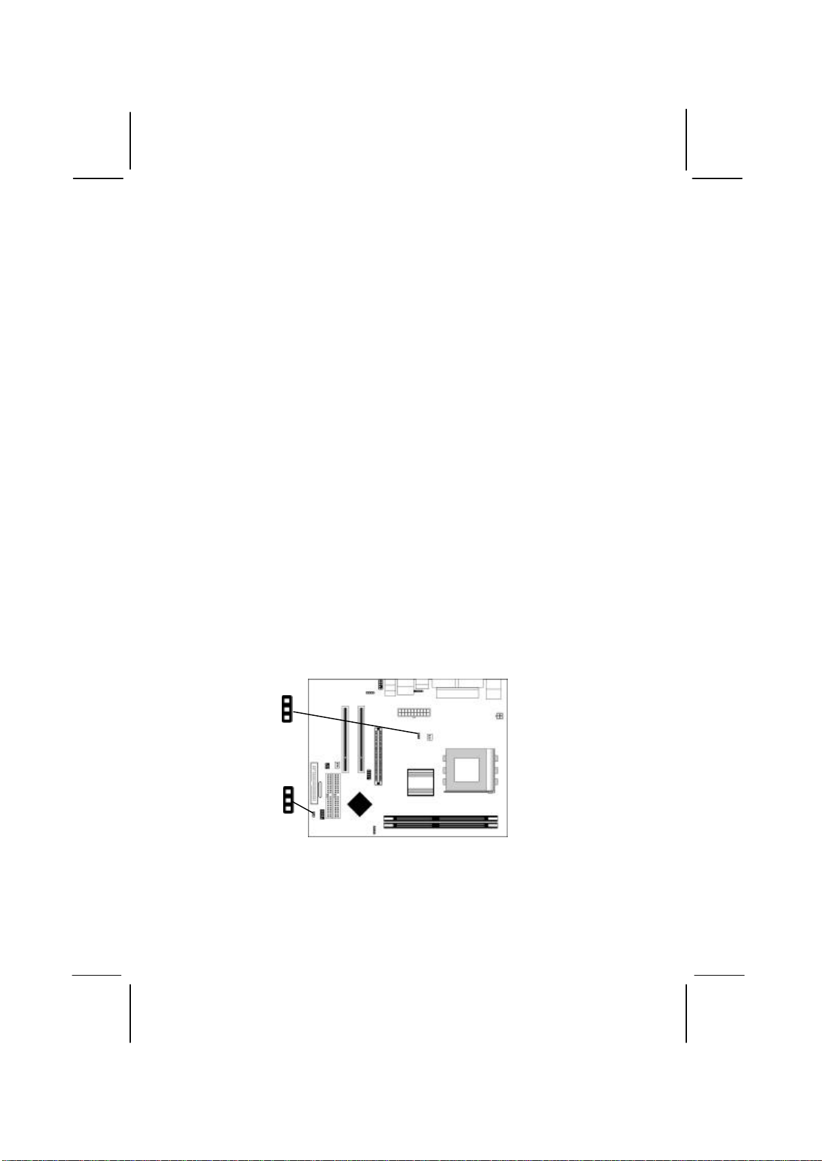
Mainboard Components
This diagram below identifies major components on the mainboard.
Note:Any jumpers on your mainboard that do not appear in
the illustration above are for testing only.
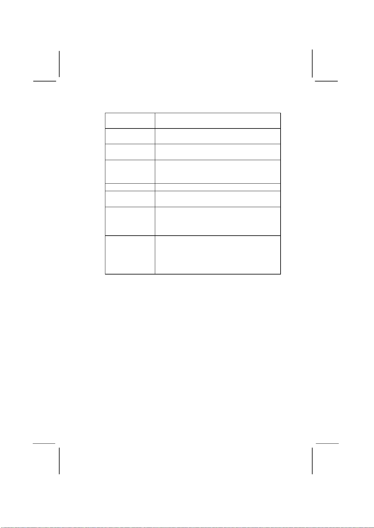
I/O Ports
The illustration below shows a side view of the built-in I/O ports
on the mainboard.
(shared
with
READER1)
(optional)
9
PS/2 Mouse Use the upper PS/2 port to connect a PS/2
pointing device.
PS/2 Keyboard Use the lower PS/2 port to connect a PS/2
keyboard.
LPT1 Use LPT1 to connect printers or other
parallel communications devices.
COM1 Use the COM port to connect serial devices
such as mice or fax/modems. COM1 is
identified by the system as COM1.
VGA Use the VGA port to connect VGA devices.
LAN Port
(optional) Connect an RJ-45 jack to the LAN port to
connect your computer to the Network.
USB Ports Use the USB ports to connect USB devices.
Note: The lower USB port located beside the
VGA port is shared with the READER1
connector.
Audio Ports Use the three audio ports to connect audio
devices. The first jack is for stereo Line-In
signal. The second jack is for stereo Line-
Out signal. The third jack is for
Microphone.
Installing the Processor
This mainboard has a Socket 462 processor socket. When choosing
a processor, consider the performance requirements of the system.
Performance is based on the processor design, the clock speed and
system bus frequency of the processor, and the quantity of internal
cache memory and external cache memory.
CPU Installation Procedure
Follow these instructions to install the CPU:
1. Unhook the CPU socket’s locking lever by pulling
it away from socket and raising it to the upright
position.
2. Match the pin 1 corner of CPU socket to the one of
processor, and insert the processor into the socket.
Do not use force.

10
3. Push the locking lever down and hook it under the
latch on the edge of socket.
4. Apply thermal grease to the top of the CPU.
5. Lower the CPU fan/heatsink unit onto the CPU and
CPU socket, and then use the retention module
clamps to snap the fan/heatsink into place.
6. Plug the CPU fan power cable into the CPU
cooling fan power supply (CPUFAN1) on the
mainboard.
Install Memory Modules
This mainboard accommodates two 184-pin 2.5V unbuffered
Double Data Rate SDRAM (DDR SDRAM) Dual Inline Memory
Module (DIMM) sockets, and supports up to 2.0 GB
of 200/266 MHz DDR SDRAM.
DDR SDRAM is a type of SDRAM that supports data transfers on
both edges of each clock cycle (the rising and falling edges),
effectively doubling the memory chip’s data throughput. DDR
DIMMs can synchronously work with 100 MHz or 133 MHz
memory bus.
DDR SDRAM provides 1.6 GB/s or 2.1 GB/s data transfer rate
depending on whether the bus is 100 MHz or 133 MHz.
DDR SDRAM uses additional power and ground lines and requires
184-pin 2.5V unbuffered DIMM module.
DDR1
DDR2
11
Installation Procedure
These modules can be installed with up to 2 GB system memory.
Refer to the following to install the memory modules.
1. Push the latches on each side of the DIMM socket
down.
2. Align the memory module with the socket. The
DIMM sockets are keyed with notches and the
DIMMs are keyed with cutouts so that they can
only be installed correctly.
3. Check that the cutouts on the DIMM module edge
connector match the notches in the DIMM socket.
4. Install the DIMM module into the socket and press
it firmly down until it is seated correctly. The
socket latches are levered upwards and latch on to
the edges of the DIMM.
5. Install any remaining DIMM modules.
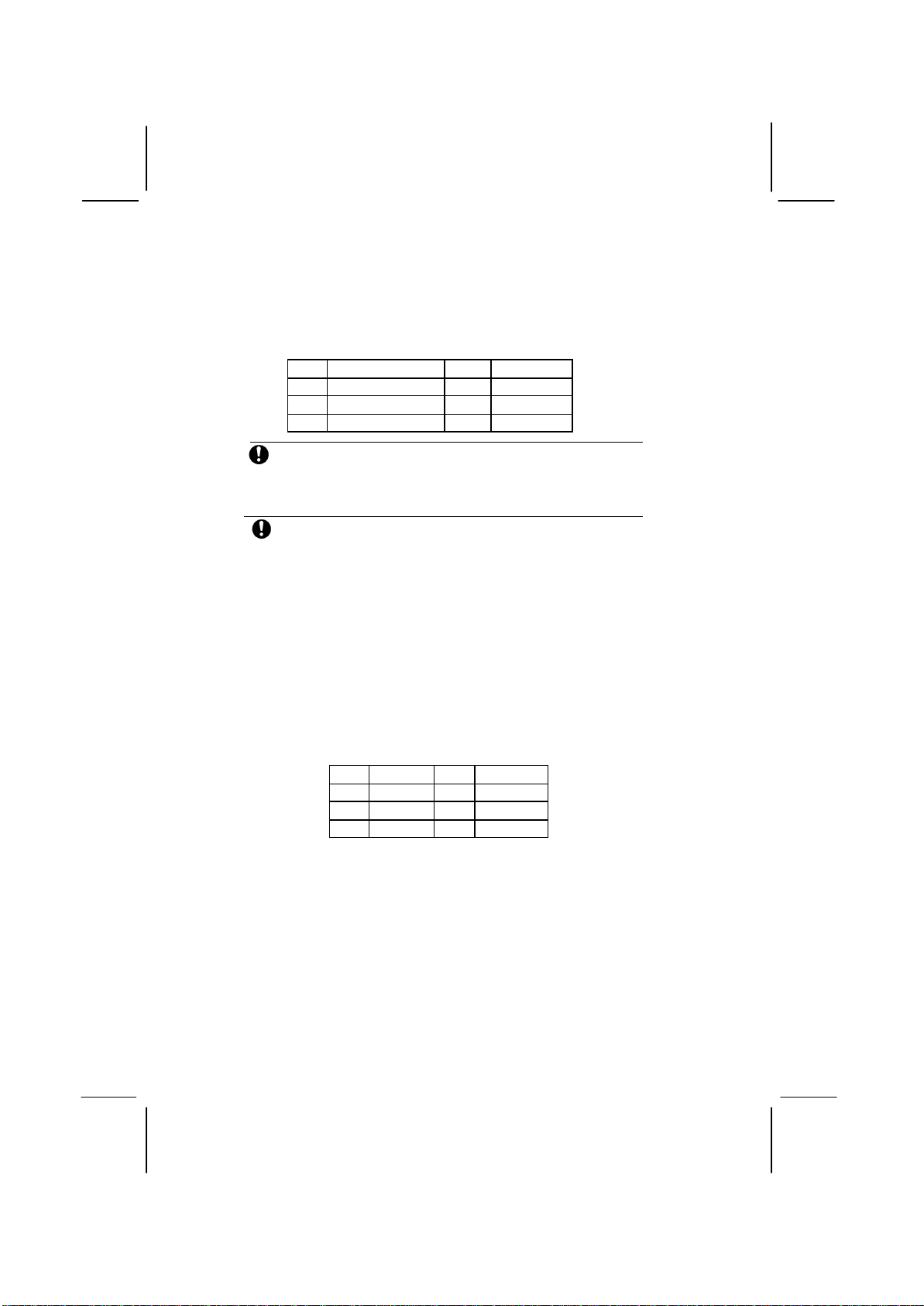
Jumper Settings
Jumpers are sets of pins connected together with jumper caps. The
jumper caps change the mainboard’s operation by changing the
electronic circuits on the mainboard. If we connect two pins with a
jumper cap, these pins are SHORT; if remove a jumper cap from
these pins, they are OPEN.
1
JP2
JP3
1

12
Jumper JP2: Clear CMOS Memory
This jumper can clear the CMOS memory. You may need to clear
the CMOS memory if the settings in the Setup Utility are incorrect
that your mainboard can’t operate. To clear the CMOS memory,
disconnect all the power cables, and then move the jumper cap into
the CLEAR setting for a few seconds.
Function Jumper Setting
Normal Short Pins 1-2
Clear CMOS
Short Pins 2-3
Jumper JP3: CPU Clock Selector
This 3-pin jumper selects the processor 133 MHz or 100 MHz.
Function Jumper Setting
100 MHz Short Pins 1-2
133 MHz Short Pins 2-3
Install the Mainboard
Install the mainboard in a system chassis (case). The board is a
Micro ATX size mainboard. You can install this mainboard in an
ATX case. Ensure your case has an I/O cover plate that matches
the ports on this mainboard.
Install the mainboard in a case. Follow the instructions provided by
the case manufacturer using the hardware and internal mounting
points on the chassis.
ATX1
SYSFAN1
1
PANEL1
1
CPUPW1

13
Connect the power connector from the power supply to the ATX1
connector on the mainboard. CPUPW1 is the CPU Vcore power
connector.
If there is a cooling fan installed in the system chassis, connect the
cable from the cooling fan to the SYSFAN1 fan power connector
on the mainboard.
Connect the case switches and indicator LEDs to the PANEL1
header.
Pin Signal Pin Signal
1HDD_LED_P 2PWR/ACPI LED
3HDD_LED_N 4PWR/ACPI LED
5RESET 6POWER BUTTON
7RESET 8POWER BUTTON
9NC 10 KEY
Connecting Optional Devices
Refer to the following for information on connecting the
mainboard’s optional devices:
SPK1: Speaker Connector
Connect the cable from the PC speaker to the SPK1 header on the
mainboard.
Pin Signal Pin Signal
1+5V 2NC
3GND 4SPKR
USB3
1
SPK1
1
AUDIO2
1
SIR1
1

14
AUDIO2: Front Panel Audio Header
This header allows the user to install auxiliary front-oriented
microphone and line-out ports for easier access.
Pin Signal Pin Signal
1AUD_MIC 2AUD_GND
3AUD_MIC_BIAS 4AUD_VCC
5AUD_FPOUT_R 6AUD_RET_R
7HP_ON 8KEY
9AUD_FPOUT_L 10 AUD_RET_L
Note: If you want to connect the front panel sound jack, you have
to remove jumper caps of Pin(5-6) and Pin(9-10) from the
AUDIO2 header.
USB3: Front panel USB Connector
The mainboard has USB ports installed on the rear edge I/O port
array. Additionally, some computer cases have USB ports at the
front of the case. If you have this kind of case, use auxiliary USB
connector USB3 to connect the front-mounted ports to the
mainboard.
Pin Signal Pin Signal
1VERG_FP_USBPWR0 2VERG_FP_USBPWR0
3USB_FP_P0-4USB_FP_P1-
5USB_FP_P0+ 6USB_FP_P1+
7GROUND 8GROUND
9KEY 10 NC
1. Locate the USB3 header on the mainboard.
2. Plug the bracket cable onto the USB3 header.
3. Remove a slot cover from one of the expansion slots on the
system chassis. Install an extension bracket in the opening.
Secure the extension bracket to the chassis with a screw.
15
READER1: USB Card Reader Connector (optional)
This connector is for connecting internal USB card reader. You can
use a card reader to read or transfer files and digital images to your
computer.
Pin Signal Pin Signal
1STANDBY 5V 2USB-
3USB+ 4GND
5KEY
The READER1 is shared with the lower USB port
located beside the VGA port of the I/O back panel.
Please see “I/O Ports” for more information.
Please check the pin assignment of the cable and the
USB header on the mainboard. Make sure the pin
assignment will match before plugging in. Any
incorrect usage may cause unexpected damage to
the system. The vendor won’t be responsible for any
incidental or consequential damage arising from the
usage or misusage of the purchased product.
SIR1: Infrared Port
The infrared port allows the wireless exchange of information
between your computer and similarly equipped devices such as
printers, laptops, Personal Digital Assistants (PDAs), and other
computers. Pin Signal Pin Signal
1NC 2KEY
3+5V 4GND
5IRTX 6IRRX
1. Locate the infrared port SIR1 header on the mainboard.
2. If you are adding an infrared port, connect the ribbon cable
from the port to the SIR1 header and then secure the port to an
appropriate place in your system chassis.
16
Install Other Devices
Install and connect any other devices in the system following the
steps below.
Floppy Disk Drive
The mainboard ships with a floppy disk drive cable that can
support one or two drives. Drives can be 3.5” or 5.25” wide, with
capacities of 360K, 720K, 1.2MB, 1.44MB, or 2.88MB.
Install your drives and connect power from the system power
supply. Use the cable provided to connect the drives to the floppy
disk drive connector FDC1.
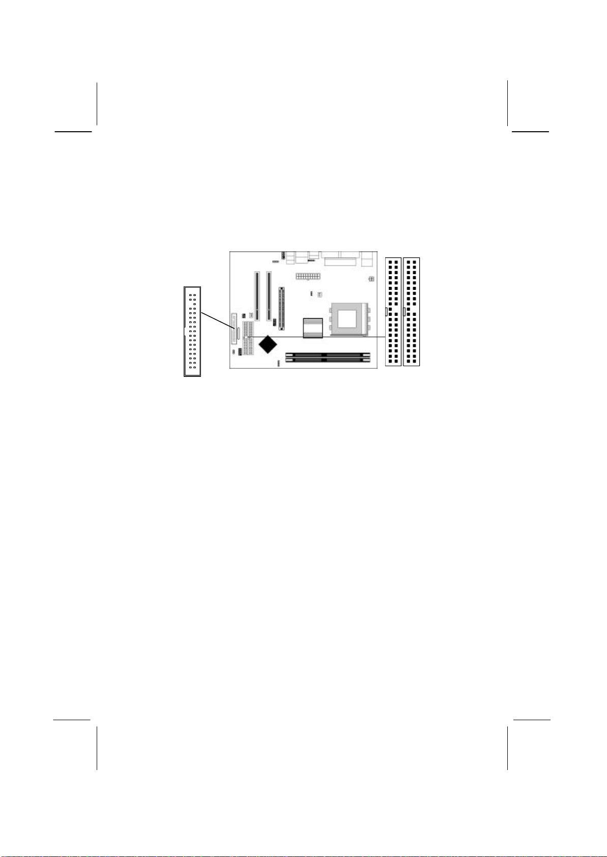
IDE Devices
IDE devices include hard disk drives, high-density diskette drives,
and CD-ROM or DVD-ROM drives, among others.
The mainboard ships with an IDE cable that can support one or two
IDE devices. If you connect two devices to a single cable, you
must configure one of the drives as Master and one of the drives as
Slave. The documentation of the IDE device will tell you how to
configure the device as a Master or Slave device. The Master
device connects to the end of the cable.
Install the device(s) and connect power from the system power
supply. Use the cable provided to connect the device(s) to the
Primary IDE channel connector IDE1 on the mainboard.
FDC1
IDE2
IDE1
1
1
1
Table of contents
Other Socket Motherboard manuals


Popular Motherboard manuals by other brands
 user manual")


Asus
Asus Z8PE-D12X - Motherboard - SSI EEB 3.61 user manual

Fujitsu Siemens Computers
Fujitsu Siemens Computers D1419 Technical manual

Gigabyte
Gigabyte 8S651M-RZ user manual

Trinamic
Trinamic TMC7300-EVAL manual

Colorful
Colorful BATTLE-AX H410M-PT PRO V20 manual

ASROCK
ASROCK 970 Extreme4 Quick installation guide


