Sirius Satellite Radio SLTC61 User manual

INFORMAZIONI COMMERCIALI PER I CONSUMATORI
COMMERCIAL INFORMATION FOR THE CONSUMER
INFORMATIONS COMMERCIALES POUR LE CLIENT
INFORMACIONES COMERCIALES PARA EL CLIENTE
HANDELSINFORMATIONEN FÜR DEN KUNDEN
COMMERCIËLE INFORMATIES VOOR DE KLANT
INFORMAZIONI TECNICHE
TECHNICAL INFORMATION
INFORMATION TECHNIQUES
INFORMACIONES TÉCNICAS
TECHNISCHE INFORMATIONEN
TECHNISCHE INFORMATIES
TYPE: FSLA
ISTRUZIONI PER L’USO
SLTC61 SLTC62 SLTC65 SLT66 SLTC68
INSTRUCTIONS FOR USE
SLTC61 SLTC62 SLTC65 SLT66 SLTC68
INSTRUCTIONS POUR L’EMPLOI
SLTC61 SLTC62 SLTC65 SLT66 SLTC68
ISTRUCCIÓNES DE USO
SLTC61 SLTC62 SLTC65 SLT66 SLTC68
BEDIENUNGSANLEITUNG
SLTC61 SLTC62 SLTC65 SLT66 SLTC68
GEBRUIKSAANWIJZIGING
SLTC61 SLTC62 SLTC65 SLT66 SLTC68
IT
GB
F
E
D
NL


3
Il simbolo sul prodotto o sulla confezione indica che il prodotto non deve essere
considerato come un normale riuto domestico, ma deve essere portato nel punto
di raccolta appropriato per il riciclaggio di apparecchiature elettriche ed elettroni-
che. Provvedendo a smaltire questo prodotto in modo appropriato, si contribuisce
a evitare potenziali conseguenze negative per l’ambiente e per la salute, che po-
trebbero derivare da uno smaltimento inadeguato del prodotto. Per informazio-
ni più dettagliate sul riciclaggio di questo prodotto, contattare l’ucio comuna-
le, il servizio locale di smaltimento riuti o il negozio in cui è stato acquistato il
prodotto. Questo elettrodomestico è marcato conformemente alla Direttiva Eu-
ropea 2002/96/CE sui riuti da apparecchiature elettriche ed elettroniche (WEEE).
IT
The symbol on the product or on its packaging indicates that this product may not be
treated as household waste. Instead it shall be handed over to the applicable collection
point for the recycling of electrical and electronic equipment. By ensuring this product
is disposed of correctly, you will help prevent potential negative consequences for the
environment and human health, which could otherwise be caused by inappropriate
waste handling of this product. For more detailed information about recycling of this
product, please contact your local city oce, your household waste disposal service or
the shop where you purchased the product. This appliance is marked according to the
European directive 2002/96/EC on waste electrical and electronic equipment (WEEE).
GB
Le symbole sur le produit ou son emballage indique que ce produit ne peut être traité
comme déchet ménager. Il doit plutôt être remis au point de ramassage concerné, se
chargeant du recyclage du matériel électrique et électronique. En vous assurant que
ce produit est éliminé correctement, vous favorisez la prévention des conséquences
négatives pour l’environnement et la santé humaine qui, sinon, seraient le résultat
d’un traitement inapproprié des déchets de ce produit. Pour obtenir plus de détails sur
le recyclage de ce produit, veuillez prendre contact avec le bureau municipal de votre
région, votre service d’élimination des déchets ménagers ou le magasin où vous avez
acheté le produit. Cet appareil est commercialisé en accord avec la directive européen-
ne 2002/96/CE sur les dèchets del équipments èlectriques et èlctroniques (WEEE).
F
El símbolo en el producto o en su embalaje indica que este producto no se pue-
de tratar como desperdicios normales del hogar. Este producto se debe entregar al
punto de recolección de equipos eléctricos y electrónicos para reciclaje. Al asegurar-
se de que este producto se deseche correctamente, usted ayudará a evitar posibles
consecuencias negativas para el ambiente y la salud pública, lo cual podría ocurrir
si este producto no se manipula de forma adecuada. Para obtener información más
detallada sobre el reciclaje de este producto, póngase en contacto con la admini-
stración de su ciudad, con su servicio de desechos del hogar o con la tienda donde
compró el producto. Este electrodomestico està marcado conforme a la directiva Eu-
ropea 2000/96/CE sobre los residuos de aparatos elèctricos y electrònicos (WEEE).
E

4
Das Symbol auf dem Produkt oder seiner Verpackung weist darauf hin, dass dieses
Produkt nicht als normaler Haushaltsabfall zu behandeln ist, sondern an einem Sam-
melpunkt für das Recycling von elektrischen und elektronischen Geräten abgegeben
werden muss. Durch Ihren Beitrag zum korrekten Entsorgen dieses Produkts schützen
Sie die Umwelt und die Gesundheit Ihrer Mitmenschen. Umwelt und Gesundheit wer-
den durch falsches Entsorgen gefährdet. Weitere Informationen über das Recycling
dieses Produkts erhalten Sie von Ihrem Rathaus, Ihrer Müllabfuhr oder dem Geschäft,
in dem Sie das Produkt gekauft haben. Dieses Elektrohaushaltsgerät ist entspre-
chend der EU-Richtlinie 2002/96/CE Über Elektro- und Elektronik – Altgeräte (WEEE).
D
Het symbool op het product of op de verpakking wijst erop dat dit product niet
als huishoudafval mag worden behandeld. Het moet echter naar een plaats wor-
den gebracht waar elektrische en elektronische apparatuur wordt gerecycled. Als
u ervoor zorgt dat dit product op de correcte manier wordt verwijderd, voorkomt
u mogelijk voor mens en milieu negatieve gevolgen die zich zouden kunnen voor-
doen in geval van verkeerde afvalbehandeling. Voor meer details in verband
met het recyclen van dit product, neemt u het best contact op met de gemeente-
lijke instanties, het bedrijf of de dienst belast met de verwijdering van huishou-
dafval of de winkel waar u het product hebt gekocht. Dit apparrat voldoet aan de
Europese richtlijnen 2002/96/CE voor elektrische en elektronische afval (WEEE).
NL

INDICE
Presentazione
Avvertenze
Versioni d’uso
Installazione
Funzionamento
Manutenzione
5
IT

6
*Nell’operazione di collegamento elettrico
assicurarsi che la presa di corrente sia munita
di collegamento a terra e vericare che i valori
di tensione corrispondono con quelli indicati
nella targhetta all’interno dell’apparecchio.
* Prima di procedere a qualsiasi operazione di
pulizia o manutenzione è necessario togliere
l’apparecchio dalla rete.
Se l’apparecchio non è provvisto di cavo es-
sibile non separabile e di spina, o di altro
dispositivo che assicuri la omnipolare disin-
serzione dalla rete, con una distanza di aper-
tura dei contatti di almeno 3 mm, allora tali
dispositivi di separazione dalla rete devono
essere previsti nell’istallazione ssa.
Se l’apparecchio è provvisto di cavo alimen-
tazione e di spina, deve essere posto in modo
che la spina sia facilmente accessibile.
Evitare l’uso di materiali che causano am-
mate (ambè) nelle immediate vicinanze
dell’apparecchio. Nel caso di fritture fare
particolarmente attenzione al pericolo di
incendio che costituiscono olio e grassi.
Particolarmente pericoloso per la sua in-
ammabilità è l’olio già usato. Non usare
griglie elettriche scoperte. Per evitare un
possibile rischio di incendio attenersi alle
istruzioni indicate per la pulizia dei ltri
antigrasso e la rimozione di eventuali de-
positi di grasso sull’apparecchio.
AVVERTENZE
* I bambini e le persone inesperte o i disa-
bili possono utilizzare l’apparecchio solo
sotto la supervisione di adulti.
* La distanza minima tra la supercie del
piano di cottura e la parte inferiore del-
la cappa deve essere 40 Cm per i prodotti
SLTC61, SLTC65, SLT66 e SLTC68 mentre
per il modello SLTC62 la distanza tra il
piano cottura e la parte inferiore del pro-
dotto non deve essere inferiore a 65Cm.
* L’aria raccolta non deve essere convo-
gliata in un condotto usato per lo scarico
di fumi di apparecchi alimentati con ener-
gia diversa da quella elettrica(impianti di
riscaldamento centralizzati, termosifoni,
scaldabagni, ecc.).
* Per lo scarico dell’aria da evacuare ri-
spettare le prescrizioni delle autorità com-
petenti.
* Prevedere un’adeguata areazione del locale
quando una cappa ed apparecchi alimentati
con energia diversa da quella elettrica (stufe
a gas, ad olio, a carbone, ecc.),vengono usati
contemporaneamente.
La cappa aspirante evacuando l’aria potrebbe
creare una pressione negativa nella stanza.
La pressione negativa del locale non deve
superare i 0,04 mbar, evitando così il risuc-
chio dei gas di scarico della fonte di calore.
Pertanto bisogna attrezzare il locale con delle
prese d’aria che alimentino un usso costan-
te di aria fresca.
Quando l’etichetta dati tecnici interna alla
cappa mostra il simbolo , l’apparecchio
è in classe II°, quindi non necessita di col-
legamento a terra.
Quando l’etichetta dati tecnici interna alla
cappa non mostra il simbolo , l’appa-
recchio è in classe I°, quindi necessita di
collegamento a terra.

7
quindi estrarre il gruppo aspirazione ruotarlo
in modo da orientare il boccaglio uscita aria
verso il lato posteriore del prodotto (Dis.15),
successivamente ricollocare il gruppo aspira-
zione nella propria sede e ripristinare le viti
rimosse in precedenza.
Utilizzando l’apposita maschera di foratura
(dis. 3A), eettuare i fori per l’installazione
della staa a muro (dis.3B); I modelli dotati di
due stae a muro (SLTC61, SLTC65, SLT66 e
SLTC68) devono essere posizionato a 400mm
dal piano cottura mentre il modello SLTC62
va posizionato a 650 mm dal piano cottura.
Fissare la o le stae a muro alla parete utiliz-
zando i tasselli e le viti in dotazione; Aggan-
ciare il corpo aspirante (dis. 4) alla staa a
muro precedentemente ssata.
Utilizzando le viti di regolazione (dis. 5 VT)
assicurarsi che la cappa aspirante sia in piano
orizzontalmente.
Sollevare il pannello frontale (vetro o acciaio)
ruotando la parte inferiore verso l’alto come
indica il dis. 6.
Nei prodotti SLTC61, SLTC65, SLT66 e SLTC68
rimuovere il ltro antigrasso;
In corrispondenza dei fori indicati dalle frecce
nel Dis. 7, praticare n° 2 fori alla parete di
diametro 8 mm, ed inserire i tasselli in dota-
zione al prodotto.
Avvitare le viti in dotazione in modo da ssa-
re ulteriormente il prodotto alla parete;
Ripristinare il ltro antigrasso e richiudere il
pannello frontale.
Per il modello SLTC62, dopo aver sollevato il
vetro, in corrispondenza dei fori indicati dalle
frecce g. 8, praticare n° 2 fori alla parete di
diametro 8mm, ed inserire i tasselli.
Avvitare le viti in dotazione in modo da ssa-
re ulteriormente il prodotto alla parete.
Versione aspirante.
Mediante i tasselli e le viti in dotazione ssare
alla parete e/o al sotto la staa supporto
tubo (dis. 9).
Collegare la angia uscita aria del motore al
foro di evacuazione tramite un tubo adatto.
Eettuare il collegamento elettrico.
Posizionare i due tubi decorativi sopra al cor-
po aspirante; sollevare il tubo interno an-
chè arrivi al sotto; quindi ssarlo alla staa
supporto tubo utilizzando n° 2 viti autolet-
tanti in dotazione.
INSTALLAZIONE
Vericare che tutti i componenti non siano
danneggiati, in caso contrario contattare il
rivenditore e non proseguire con l’installa-
zione.
Prima di procedere con l’installazione legge-
re attentamente tutte le istruzioni di seguito
riportate:
- Utilizzare un tubo evacuazione aria che
abbia la lunghezza minima possibile, limitato
numero di curve, materiale approvato nor-
mativamente;
- Evitare cambiamenti drastici di sezione
(diametro costante consigliato Ø 150 mm o
pari superci);
- Per il mancato rispetto delle precedenti
istruzioni la ditta fornitrice non risponde-
rà per problemi di portata o di rumorosità e
nessuna garanzia sarà prestata.
I modelli SLTC61, SLTC65, SLT66 e SLTC68
sono stati progettati con la possibilità di
orientare l’uscita aria nel lato posteriore del
prodotto; nel caso si intenda utilizzare questa
funzione occorre rimuovere le n° 10 viti del
supporto gruppo aspirazione (Dis.14 )
VERSIONI D’USO
L’apparecchio è già predisposto sia per la ver-
sione ltrante sia per la versione aspirante.
* Nella versione ltrante (dis. 1) l’aria ed i
vapori convogliati dall’apparecchio, vengono
depurati sia da un ltro antigrasso sia da un
ltro al carbone attivo e rimessi in circolazio-
ne nell’ambiente attraverso le griglie laterali
del camino. Nell’uso in versione ltrante è
necessario l’uso di un deviatore aria (dis.1A),
che posto nella parte superiore del tubo per-
metta il riciclo dell’aria nell’ambiente.
* Nella versione aspirante (dis. 2) i vapori
vengono convogliati direttamente all’ester-
no, tramite un condotto di evacuazione che si
collega con la parte superiore della parete o
del sotto. L’utilizzo sia del ltro al carbone
sia del deviatore aria non è necessario.

8
Versione ltrante.
Mediante i tasselli e le viti in dotazione ssare
alla parete e/o al sotto la staa supporto
tubo (Dis. 9).
Fissare il deviatore aria al camino superio-
re (dis. 10), in prossimità dei fori posti nella
parte posteriore del camino.
Collegare la angia uscita aria del motore al
deviatore aria tramite un tubo adatto.
Eettuare il collegamento elettrico.
Posizionare i due tubi decorativi sopra al cor-
po aspirante; sollevare il tubo interno an-
chè arrivi al sotto; quindi ssarlo alla staa
supporto tubo utilizzando n° 2 viti autolet-
tanti in dotazione.
FUNZIONAMENTO
Mod. SL TC – Glass (dis. 11)
A : ON/OFF luci
B : ON motore/aumento velocità
C : indicatori velocità
D : riduzione velocità / OFF motore
E : temporizzatore 10 min.
La pulsantiera Touch control su vetro per-
mette di impostare la funzione desiderata
sorando il relativo tasto. Se il prodotto SLTC
rimane privo di alimentazione elettrica, al
momento del ripristino delle funzioni richiede
15 secondi per l’autodiagnosi, nel frattempo
potrebbe non funzionare correttamente.
Mod. SL TC - versione Touch Control (Dis.16)
A : INTERRUTTORE ON/OFF LUCI
B : RIDUZIONE VELOCITA’/ OFF MOTORE
C : INDICATORI VELOCITA’
D : ON MOTORE / AUMENTO VELOCITA’E:
TEMPORIZZATORE 10 min.
La pulsantiera Touch Control permette di im-
postare la funzione desiderata sorando il re-
lativo tasto. Le spie luminose (dis. 16C) posi-
zionate al centro della pulsantiera indicano la
velocità di aspirazione impostata. Nel caso di
errato funzionamento della pulsantiera, pre-
mere due volte il tasto reset di colore rosso
visibile all’interno della cappa dopo l’apertura
del pannello frontale. Se il prodotto SLTC ri-
mane privo di alimentazione elettrica, al mo-
mento del ripristino delle funzioni richiede
15 secondi per l’autodiagnosi, nel frattempo
potrebbe non funzionare correttamente.
Mod. SLT - versione Telecomando (Dis.18)
Radiocomando per il comando a distanza di
cappe aspiranti.
Caratteristiche tecniche:
- Alimentazione a pila alkalina: 12V mod 23°
- Frequenza di lavoro : 433.92 MHz
- Consumo max. : 25 mA
- Temperatura d’esercizio : - 20 + 55°C
Descrizione di funzionamento:
- Per accendere o spegnere la cappa premere
una sola volta il tasto:
- Per aumentare la velocità no alla 4a (max)
premere il tasto :
- Per diminuire la velocità no alla 2a pre-
mere il tasto:
- Per tornare alla 1 a velocità da una superio-
re premere due volte il tasto:
- Per accendere e spegnere le luci premere
il tasto:
Per impostare il temporizzatore premere il
tasto:
Il led più a destra inizierà a lampeggiare
(ogni 5 secondi), la cappa rimane accesa per
un tempo di 10 min alla velocità seleziona-
ta per poi spegnersi automa-ticamente. Au-
mentando o diminuendo la velocità mentre
il temporizzatore è attivo, quest’ultimo viene
disabilitato.

9
MANUTENZIONE
Un’accurata manutenzione garantisce un
buon funzionamento ed un buon rendimento
nel tempo.
Una cura particolare va rivolta al ltro anti-
grasso.
Nei modelli SLTC61, SLTC65, SLT66 e SLTC68
la rimozione del ltro avviene in primo luogo
aprendo il pannello frontale (dis. 6) , succes-
sivamente operando sull’apposita maniglia
del ltro e ruotandolo verso l’esterno. Il ltro
viene inserito nell’operazione inversa.
E’ necessario mantenere pulito il canale rac-
colta olio posto sotto al ltro antigrasso, la
rimozione avviene svitando i due pomelli di
ssaggio e slandolo dalla sede come dimo-
stra il dis. 17.
Per il prodotto SLTC62 occorre aprire il pan-
nello frontale in vetro ruotandolo verso l’alto
(Dis.12), successivamente slare i due ltri
dalla sede come dimostra il Dis. 12 A, i ltri
vengono inseriti nell’operazione inversa.
Dopo 30 ore di esercizio della cappa, la
pulsantiera segnalerà la saturazione del
ltro mediante l’illuminazione simultanea
degli indicatori di velocità; Per il reset pre-
mere il tasto temporizzatore .
La pulizia del ltro antigrasso può essere
eseguita a mano o in lavastoviglie.
La pulizia avviene in rapporto all’uso, almeno
una volta ogni due mesi.
* Nel caso d’uso dell’apparecchio in versione
ltrante, è necessario sostituire il ltro car-
bone attivo periodicamente. Il ltro carbo-
ne attivo si rimuove togliendo prima il l-
tro antigrasso, seguendo le istruzioni sopra
descritte, successivamente tirando l’apposita
linguetta in plastica del ltro carbone sgan-
ciandolo dalla sua sede. Il ltro carbone viene
inserito nell’operazione inversa. La sostitu-
zione del ltro al carbone avviene in rapporto
all’uso, almeno una volta ogni sei mesi.
Per la pulizia dell’apparecchio stesso viene
consigliato l’uso di acqua tiepida e detersivo
neutro, evitando l’uso di prodotti contenenti
abrasivi.
Modalità di funzionamento:
Nel caso siano installati due sistemi cappa-
radiocomando nello stesso locale o nelle im-
mediate vicinanze i sistemi avendo lo stesso
codice di trasmis-sione potrebbero essere
inuenzati quindi è necessario cambiare il
codice di un solo radiocomando.
ATT.: La batteria deve essere sostituita ogni
anno per garantire la portata ottimale del tra-
smettitore, per sostituire la batteria scarica
rimuovere il coperchio di plastica, togliere la
batteria in uso e inserirne una nuova rispet-
tando la polarità indicata nel contenitore. La
batteria usata deve essere smaltita negli ap-
positi contenitori.
Il prodotto è dotato di un dispositivo elettro-
nico che permette lo spegnimento automati-
co dopo quattro ore di funzionamento dal-
l’ultima operazione eseguita.
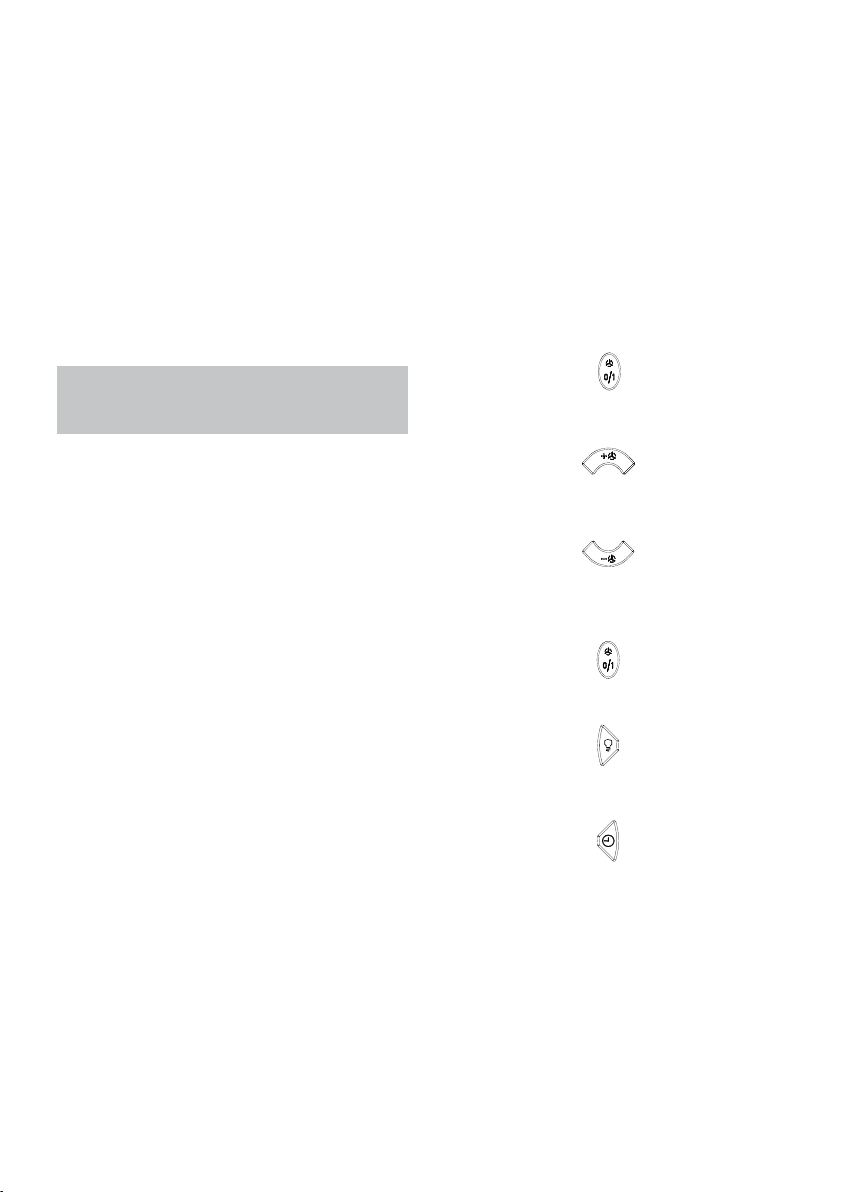
Generazione di un nuovo codice di tra-
smissione:
Il radiocomando viene fornito dalla fabbrica
con dei codici predeniti. Se si desidera una
nuova generazione di codici, occorre ese-
guire la seguente procedura: Premere con-
temporaneamente i tasti UP (+), STOP (0/1)
e DOWN (-) in modo continuo per 2 secondi,
nello stesso tempo si avrà l’accensione dei
led, succes-sivamente premere i tasti UP (+)
e DOWN (-), 3 lampeggi dei led indicheran-
no che l’operazione è stata completata. ATT:
questa operazione cancella in maniera deni-
tiva i codici preesistenti.
Apprendimento del nuovo codice di tra-
smissione:
Dopo aver cambiato il codice di trasmissio-
ne nel radiocomando, occorre far apprendere
alla centrale elettronica della cappa aspirante
il nuovo codice nel seguente modo: premere
il tasto d’emergenza (visibile dopo l’apertura
del pannello frontale) per due volte conse-
cutive in modo da togliere alimen-tazione al
prodotto e ripristinarla, da questo momento
ci sono 15 secondi di tempo per premere il
tasto luce per far si che la cappa si sin-
cronizzi con il nuovo codice.

10
SOSTITUZIONE LAMPADE SLTC61
* Per sostituire la lampada dicroica orientabile
occorre, in primo luogo, rimuovere la ghie-
ra di sostegno stringendo i bordi adiacenti
(Dis.13), successivamente slare la lampada
e sostituirla con una delle stesse caratteri-
stiche.
SOSTITUZIONE LAMPADE SLTC62, SLTC65,
SLT66 e SLTC68
* Per sostituire la lampada dicroica, slare la
lampada inserendo un piccolo giravite o un
qualsiasi utensile appuntito tra lampada e la
sede in acciaio, sostituire con una lampada
delle stesse caratteristiche.
* La sostituzione del cavo alimentazione deve
essere eseguita esclusivamente da personale
autorizzato.

CONTENTS
Warnings
Uses
Installation
Working
Maintenance
11
GB

12
* Before carrying out any cleaning or main-
taining operations, the appliance needs to
be removed from the electric grid. If the ap-
pliance is not provided with a non-separable
exible cable and plug, or with another de-
vice ensuring omnipolar disconnections from
the grid, with an opening distance between
the contacts of at least 3 mm, then such di-
sconnecting devices must be supplied within
the xed installation.
If the xed appliance is endowed with a sup-
ply cord and a plug, the appliance has to be
put in a place where the plug can be reached
easily.
* The use of materials which can burst into
ames should be avoided in close proxi-
mity of the appliance. When frying, please
pay particular attention to re risk due to
oil grease. Being highly inammable, fried
oil is especially dangerous. Do not use un-
covered electric grills.
In order to avoid possible re risk, all in-
structions for grase-lter cleaning and for
removing eventual grease deposits should
be strictly followed.
WARNINGS
* The appliance is not intended for use by
young children or inrm persons without
supervision. Young children should be su-
pervised to ensure they do not play with
the appliance.
The minimum distance between the cook
top surface and the lower side of the
cooker hood must be 40 cm for models
SLTC61, SLTC65, SLT66 and SLTC68, while
for model SLTC62, the minimum distan-
ce between the cook top and the bottom
of the appliance must not be lower than
65Cm.
* The air sucked can’t be conveyed throu-
gh or into a duct used to let out fumes
from appliances fed by energy other than
electric power (eg. centralized heating, ra-
diators, water-heaters, etc.).
* To evacuate the air outlet, please comply
with the pertaining rules given by compe-
tent authorities.
* Provide the room with an adequate aeration
when a cooker hood and appliances fed by
energy other than electric power (gas-, oil-,
or coal- stoves, etc.) are used simultaneously.
The cooker hood, when evacuating the sucked
air, could generate a negative pressure in the
room- which can’t exceed the limit of 0.04
mbar, in order to avoid the suck of exhausts
deriving from the heat-source. Therefore the
room should be provided with air-intakes to
allow a costant ow of fresh air.
If the rating lable in the cooker-hood
shows the symbol , the appliance is
built in class II° and it does not need any
earth connection.
If the rating lable in the cooker-hood does
not show the symbol , the appliance is
built in class I° and it needs the earth con-
nection.
* When performing the electrical connections on
the appliance, please make sure that the current-
tap is provided with earth connection and that
voltage values correspond to those indicated on
the label placed inside the appliance itself.
USES
The appliance is already arranged both for
ltering and for suction performances.
* In its ltering version (Fig.1), the air and
fumes conveyed by the appliance are depured
both by a grease lter and by an active coal
lter, and put again into circulation through
the side-grids of the chimney. For this ver-
sion an air deector placed on the superior
part of the pipe and allowing air-recycling is
necessary (Fig.1A).
* In its sucking version (Fig.2), fumes are di-
rectly conveyed outside, through an evacua-
tion duct connected with the superior part of
the wall or the ceiling. Both coal lter and air
deector are not necessary in this case.

13
Lift the front panel (glass or steel) by rotating
its lower side upwards, as shown in Fig. 6.
Remove the grease-lter in models SLTC61,
SLTC65, SLT66 and SLTC68;
In connection with the holes indicated by the
arrows in Fig. 7, drill two 8 mm diameter ho-
les into the wall, and insert the screw anchors
supplied with the appliance. Screw in the
screws supplied with the appliance, in order
to further secure the appliance to the wall;
place the grease lter back into its seat and
close the front panel.
For model SLTC62, after having lifted up the
glass, in connection with the holes indicated
by the arrows in g. 8, drill two 8 mm dia-
meter holes into the wall and insert the screw
anchors.
Screw in the screws supplied with the ap-
pliance, in order to further secure the ap-
pliance to the wall.
Sucking version
* Fix the pipe-bearing stirrup (Fig.10Y) to the
wall or ceiling by using the proper reinforce-
ments and screws in equipment. Connect the
cooker-hood ange with the evacuation hole
by using a proper pipe.
(For versions with display only) Lift the lower pipe
until the cable strap coming out of the sucking
unit is uncovered and connect it to the display
cable strap. Put down the lower pipe while paying
attention it is being properly introduced into the
hood. Perform the electrical connections. The
superior end of the pipe is to be xed laterally
to the pipe bearing (Fig.11Y) by using the two
self-threading screws. Now mount the inferior
chimney by inserting it through the front side of
the cooker hood and then turning it down until
it is xed inside (Fig.11).
Filtering version
* In the ltering version the air deviator is xed
through the screws supplied (Fig.12), by using
the holes which are on the back of the upper
telescopic section. Connect the ange of the
appliance with the air deviator through an ap-
propriate pipe. Connect the appliance with the
electric mains. (For versions with display only)
Lift the lower pipe until the cable strap coming
out of the sucking unit is uncovered and con-
nect it to the display cable strap. Put down the
lower pipe while paying attention it is being
properly introduced into the hood.
Fix the upper chimney as indicated in bic. 11.
INSTALLATION
Before installing the appliance, make sure
that none of the parts is damaged in any way.
In case of damaged parts, contact your retai-
ler and do not proceed with installation.
Read all of the following instructions with
care before installing the appliance.
- Use an air outlet pipe of the shortest pos-
sible length.
- Limit the number of pipe bends.
- Use a material approved by standards and
regulations.
- Avoid any sudden changes in pipe section
(recommended constant diameter: 150 mm
or equal surface area).
Models SLTC61, SLTC65, SLT66, and SLTC68
have been designed in order to position the
air outlet towards the upper or the rear side
of the appliance. In case you want to position
the air outlet towards the rear side, it is ne-
cessary to remove the no. 10 screws of the
suctioning unit support (Fig.14), then take
the suctioning unit out, by rotating it in such
a way to position the air outlet nozzle towar-
ds the rear side of the appliance (Fig.15); then
place the suctioning unit back into its posi-
tion, and re-insert the previously removed
screws.
Using the drilling jig supplied (dis. 3A). Drill
the holes for the wall bracket installation
(Fig.3B); models equipped with two wall brac-
kets (models SLTC61, SLTC65 and SLT66)
must be positioned at 400mm from the cook
top, while the SLTC62 model must be posi-
tioned at 650 mm from the cook top.
Mount the brackets on the wall using the
screws supplied and hang the hood dodj (g.
4) on the bracket previously mounted. Using
the adjustment screws (g. 5VT) make sure
the hood is orizontallj well aligned.

14
WORKING
Mod. SL TC - Touch Control version (Dis.21)
A: Light switch On/O
B: Reduce speed
C: Luminous telltale
D: Incrase speed
E: 10 - minute timer
The touch control key allows the function
desired by touching the relative key. The lu-
minous telltales (g. 16C) positioned at the
center of the keyboard indicate the suction
speed set. In case of an active timer, the up-
per telltale (C) ashes.
If the push button console malfunctions, re-
move the grease lters and press the red but-
ton inside the appliance twice.
If the electrical power supply to the product
SLTC is cut, 15 seconds are needed for self-
diagnostics after the functions are restored. In
the meanwhile, its operation may be incorrect.
Mod. SL TC - Glass (Dis.24)
A: Light switch On/O
B: Reduce speed
C: Luminous telltale
D: Incrase speed
E: 10 - minute timer
The touch control key allows the function de-
sired by touching the relative key.
If the electrical power supply to the product
SLTC is cut, 15 seconds are needed for self-
diagnostics after the functions are restored. In
the meanwhile, its operation may be incorrect.
Mod. SLT
Technical data:
Alkaline battery powered: 12v mod. 23A
Operating frequency: 433.92 Mhz
Combinations: 4096
Max. consumption: 25mA
Operating temperature: -20° : +55°C
- To light the cooker hood on or to
light it o press the button:
- To increase the speed up to the
fourth one press the button:
- To reduce the speed up to the
second one press the button:
- To go from a high speed back to
the rst one press twice the button:
- To give power to the lights or to
shut them down press the button:
- To set the timer up press the
button:
The LED on the right side will start to ash
(every 5 seconds), the hood will work for 10
minutes at the selected speed and then it li-
ghts automatically o. If the client increases
or reduces the speed while the timer is on,
this is automatically stopped.
Standard conguration
If two cookerhoods-radiocontrol system are
installed in the same room or in the immediate
vicinity, each system may aect the operation
of the other, due to the fact that they have the
same code. Therefore it will be necessary to
change the code of one of the radio controls.

15
Warning:
The battery should be replaced eve-
ry yearto guarantee the optimal range of
the transmitter. To replace the exhausted
battery, take the plastic lid o, remove the
battery and replace it with a new one, ob-
serving the correct battery polarities. Used
batteries should be discarded in special
collection bins.
Generating a new transmission code
The radiocontrol is supplied by the manufac-
turer with default codes stored. If you want to
create a new set of codes, proceed as follows:
press and hold the UP, STOP and DOWN but-
tons simultaneously for 2 seconds. Afterthe
LEDS light up, press the UP and DOWN button
swithin 5 seconds. The LEDS will ash 3 times
to indicate that the process is completed.
WARNING: This procedure deletes all pre-
viously stored codes.
Learning the new transmission code
After changing the transmission code on
the radio control, the cooker hood electro-
nic control unit must be made to set the new
code as follows : press the main Power O
button on the cookerhood and then restore
power to the electronic control unit. Within
the next 15 seconds, press the Light button.
This will ensure the control unit is synchroni-
zed with the new code.

16
MAINTENANCE
* To clean the appliance itself tepid water and
neutral detergent are recommended, whi-
le abrasive products should be avoided. For
steel appliances specialized detergents are
recommended (please follow the instructions
indicated o the product itself to obtain the
desired results).
SLTC61 LAMP REPLACEMENT
To replace the adjustable dichroic lamp, rst,
remove the supporting ring nut by clasping
its adjacent edges (Fig.13), then remove the
lamp and replace it with another one with the
same characteristics.
SLTC62, SLTC65, SLT66 and SLTC68 LAMP
REPLACEMENT
To replace the dichroic lamp, remove the
lamp (Fig. 19) by inserting a screwdriver or
another sharp tool between the lamp and its
chrom support and replace it with a lamp of
the same kind.
* If the supply cord is damaged, it must be
replaced by the manufacturer or its sevice
agent or a similarly qualied person in order
to avoid a hazard.
* An accurate maintenance guarantees good
functioning and long-lasting performance.
* Particular care is due to the grease lter
panel.
In order to remove the grease-lter in models
SLTC61, SLTC65, SLT66 and SLTC68 it is ne-
cessary to open the front panel rst (Fig. 6),
then grasp the lter handle and rotate it ou-
twards. To insert the lter please follow the
inverse procedure.
For model SLTC62, it is necessary to open
the front glass panel, by rotating it upwards
(Fig.12), then take the two grease-lters out
from their seat, as shown in Fig. 12 A.
To insert the lter please follow the inverse
procedure.
After 30 hours working (model SL-Modu-
le Luxury version), the push button control
panel will signal the saturation of the grease
lter by lighting all the buttons. In the SLTC
models (Touch Control Version) the grease
lter saturation is signalled by the ashing
of the two central push buttons (Fig. 21 C).
Press the timer button to reset .
The grease lter needs cleaning by regular
hand-washing or in dishwashers every two
months at least or depending on its use.
* In case the appliance is used in its ltering
version, the active coal lter (Fig.16-20Z)
needs to be periodically replaced.
The coal lter can be removed by removing
the grease lter rst (Fig.4A-16B), and by
pulling its special plastic tongue until it is un-
fastened from its slot. Re-insert the coal lter
by operating in the opposite way. The coal
lter needs replacing depending on the use,
but however every six months at least.

INDEX
Attention
Version de l’appareil
Installation
Fonctionnement
Entretien
17
F

18
vériez aussi que les valeurs de tension cor-
respondent à celles qui sont indiquées sur la
plaque des caractéristiques de l’appareil, qui
se trouve à l’intérieur de celui-ci.
*Avant de procéder à une opération d’entre-
tien ou de nettoyage quelconque, il faut dé-
brancher l’appareil.
Si votre appareil n’a pas pas de câble exible
qui ne peut pas être séparé, ni de prise ou
bien d’autre dispositif qui garantisse le dé-
branchement de tous les pôles du réseau,avec
une distance d’ouverture entre les contacts
d’au moins 3mm., ces dispositif de sépara-
tion du réseau doivent alors être prévus dans
l’installation xe.
Si l’appareil xé est pourvu du câble de l’ali-
mentation et une che, l’appareille doit être
placé de manière que la che soit facilement
accessible.
* Evitez d’utiliser des matériaux qui causent
des ambées à proximité de l’appareil. Dans
le cas de fritures, faites tout particulière-
ment attention au danger d’incendie que
représentent les huiles et les corps gras. A
cause de son inammabilité l’huile usagée
est particulièrement dangereuse. N’utilisez
pas de grilles électriques découvertes. Pour
éviter des risques d’incendie possibles sui-
vez les instructions donnèes concernant le
nettoyage des ltres anti-graisses et sur
la façon d’enlever des dépots éventuels de
graisse sur l’appareil.
ATTENTION
* Les enfants, les personnes dépendantes ou
handicapée ne peuvent utiliser l’appareil que
si elles sont sous la surveillance d’adultes.
Pour les modèles SLTC61, SLTC65 et SLT66,
la distance minimale entre la table de cuis-
son et la partie inférieure de la hotte aspi-
rante doit être 40 cm, tandis que pour le
modèle SLTC62 la distance entre la table
de cuisson et la partie inférieure de la hot-
te aspirante ne doit pas être inférieure à
65 cm.
* L’air aspiré ne doit pas être canalisé dans
un conduit qui est utilisé pour évacuer les
fumées produites par des appareils alimen-
tés par des sources d’énergie autres que
l’énergie électrique (installations de chauf-
fage central, radiateurs, chaue-eau, etc.).
* Pour évacuer l’air qui doit être éliminé
respectez les prescriptions des autorités
compétentes.
* Prévoyez une aération de la pièce adéquate
quand une hotte et des appareils alimentés
par une énergie autre que l’énergie électri-
que (poêle à gaz, à charbon, etc.) sont uti-
lisés en même temps. En eet, en évacuant
l’air, la hotte pourrait créer une dépression
dans la pièce. La pression négative de la pièce
ne doit pas dépasser 0,04 mbar, évitant ainsi
que la source de chaleurs provoque un appel
des gaz qui doivent être évaqués. Il est donc
nécessaire d’équiper la pièce de prises d’air
alimentant un ux d’air frais constant.
Quand l’ètiquette des caractéristiques te-
chniques, qui se trouve dans la hotte mon-
tre le symbole , l’appareil est en classe
II°, par conséquent il n’a pas besoin de au-
cune connexion à la terre.
Quand l’ètiquette des caractéristiques te-
chniques, qui se trouve dans la hotte ne
montre pas le symbole , l’appareil est
en classe I°, par conséquent il a besoin de
la connexion à la terre.
* Lors du raccordement électrique assurez-
vous que la prise de courant soit munie de
mise à la terre;
VERSIONS DE L’APPAREIL
L’appareil peut être utilisé en version recycla-
ge ou aspirante.
* Dans la version recyclage (Fig.1), l’air et les
vapeurs convoyés par l’appareil sont épurés
par une grille anti-graisse et par un panneau
en bre de charbon actif, et après ils sont re-
mis en circulation dans la pièce par les petites
grilles latérales de la cheminée. Dans la ver-
sion recyclage, il est nécessarie d’utiliser un
commutateur d’air (Fig. 1A) qui, placé dans le
dessus du tube, permet le recyclage de l’air
dans la pièce.

19
Soulever le panneau frontal (en verre ou acier)
en tournant la partie inférieure vers le haut,
comme indiqué dans la gure 6.
Pour les modèles SLTC 61, SLTC65 et SLT66
enlever les ltres anti-graisse.
En correspondance des trous, indiqués par
les èches dans la gure 7, eectuer n. 2
trous dans le mur d’un diamètre de 8 mm et
introduire les chevilles fournies. Visser les vis
fournies de façon de xer bien le produit au
mur. Replacer le ltre anti-graisse et refer-
mer le panneau frontal.
Pour le model SLTC62, après avoir soulevé le
verre, en correspondance des trous, indiqués
par les èches dans la gure 8, eectuer n. 2
trous dans le mur d’un diamètre de 8 mm et
introduire les chevilles.
Visser les vis fournies de façon de xer bien
le produit au mur.
* Version aspirante
Fixez l’étrier support tuyau (Fig.10Y) sur la
paroi/plafond au moyen des tasseaux et des
vis en dotation. Faites la liaison entre la bride
de raccordement de la hotte et le trou d’éva-
cuation de l’air au moyen d’un tube spécial.
Faire la connexion électrique. (Seulement pour
la version munie d’acheur). Soulever le tuyau
inférieur jusqu’à découvrir le câble plat qui sors
du groupe d’aspiration et le connecter au câble
plat de l’acheur. Abaisser de nouveau le tu-
yau inférieur veillant à ce qu’il entre de façon
correcte dans le logement de la hotte aspirante.
L’avant du tube est xé latéralement au support
tuyau (Fig.11) par deux vis autolettantes.
* Version ltrante
En version ltrante le deviateur d’air est xé par
les vis fournies (Fig.12) à travers les trous situés
dans la partie postérieure du raccord téléscopi-
que supérieure. Connecter la buse de la hotte
au deviateur par un tube approprié et proceder
à la connexion électrique.(Seulement pour la
version munie d’acheur). Soulever le tuyau in-
férieur jusqu’à découvrir le câble plat qui sors du
groupe d’aspiration et le connecter au câble plat
de l’acheur. Abaisser de nouveau le tuyau in-
férieur veillant à ce qu’il entre de façon correcte
dans le logement de la hotte aspirante.
Fixer la partie superieure comme indiqué en
des. 11.
INSTALLATION
Avant de proceder a l’installation, verier
que tous les composants soient en bon etat;
dans le cas contraire,
contacter le revendeur et interrompre l’in-
stallation.
Avant d’installer le produit, lire attentivement
toutes les instructions reportees ci-dessous.
- Utiliser un tube d’evacuation de l’air ayant
une longueur minimum possible.
- Limiter le nombre de coudes.
- Utiliser un materiau approuve selon les
normes en vigueur.
- Eviter les changements drastiques de sec-
tion (diametre constant conseille 150 mm ou
surface equivalente).
Les modèles SLTC61, SLTC65 et SLT66 ont
étés étudiés pour orienter la sortie de l’air
par le côté supérieur ou postérieur du pro-
duit. Dans le cas où on souhaiterait orienter
la sortie de l’air vers le côté postérieur, il faut
enlever les n. 10 vis du support du groupe
d’aspiration (Figure 14) ; ensuite enlever le
groupe d’aspiration en le tournant de façon
d’orienter l’embouchure de la sortie d’air vers
le côté postérieur du produit (Figure 15). Par
la suite replacer le groupe d’aspiration à sa
place et visser de nouveau les vis précédem-
ment enlevées.
A l’aide du gabarit de perçage (g. 3A). Ef-
fectuer les trous pour l‘installation de l’étrier
(Figure 3B) ; les modèles avec deux étriers
(SLTC61, SLTC65 et SLT66) doivent être po-
sitionnés à 400 mm de la table de cuisson,
alors que le modèle SLTC62 doit être posi-
tionné à 650 mm de la table de cuisson.
Fixer les étriers en utilisant les tasseaux et les
vis en dotation; accrocher la hotte (g. 4) à
l’étrier qu’on vient de xer. En utilisant les vis
de réglage (g. 5 VT), s’assurer que la hotte
soit parfaitement horizontale.
* Dans la version aspirante (Fig.2), les va-
peurs sont convoyées directement à l’ex-
térieur par un tuyau d’évacuation à travers
la paroi/plafond. Il n’est donc pas nécessaire
d’utiliser le ltre à charbon actif ou un devia-
teur de l’air.

20
FONCTIONNEMENT
Mod. SL TC - version Touch Control (Dis.21)
A: Interrupteur On/O éclairage
B: Diminution de vitesse
C: Voyants lumineux
D: Augmentation de vitesse
E: Interrupteur 10 minutes
Le tableau à poussoirs Touch Control permet
d’établir la fonction souhaitée en eeurant
la touche concernée. Les voyants lumineux
(C) placés au centre du tableau indiquent la
vitesse d’aspiration établiée. Dans le cas de
temporisateur actif, le voyant (C) en haut
clignote. En cas de non-fonctionnement du
panneau de commande, appuyez deux fois
sur le bouton rouge; visible après l’enlève-
ment du ltre à graisse. En cas d’interruption
de l’alimentation électrique, le produit SLTC
nécessite de 15 secondes pour l’auto-dia-
gnostic avant de rétablir ses fonctions. En-
tre-temps, il pourrait ne pas fonctionner cor-
rectement.
Mod. SL TC - Glass (Dis.24)
A: Interrupteur On/O éclairage
B: Diminution de vitesse
C: Voyants lumineux
D: Augmentation de vitesse
E: Interrupteur 10 minutes
Le tableau à poussoirs Touch Control permet
d’établir la fonction souhaitée en eeurant la
touche concernée.
En cas d’interruption de l’alimentation électri-
que, le produit SLTC nécessite de 15 secon-
des pour l’auto-diagnostic avant de rétablir
ses fonctions. Entre-temps, il pourrait ne pas
fonctionner correctement.
Mod SLT
Caracteristiques techniques
Alimentation pile alkaline: 12v mod.23A
Frequence de service: 433,92 Mhz
Combinaisons : 4096
Consommation maximum: 25mA
Temperature de service: -20° : +55°C
- Pour allumer ou eteindre la hotte,
frapper une fois la touche:
- Pour augmenter la vitesse jusqu’a
la 4°(maximum) frapper la touche:
- Pour diminuer la vitesse jusqu’a
la 2° frapper la touche:
- Pour revenir sur la 1° vitesse depuis
une vitesse superieure, frapper
deux fois la touche:
- Pour allumer ou eteindre les
lumieres, frapper la touche:
- Pour programmer le temporisateur,
frapper la touche:
Le voyant lumineux a l’extreme droitese met
a clignoter (toutes les 5 secondes), la hot-
te reste allumee pendant 10 mn a la vitesse
selectionnee puis s’eteint automatiquement.
Si on augmente ou diminue la vitesse lorsque
le temporisateur est actionne, ce dernier
s’exclu automatiquement.
Modalites de fonctionnement
Si deux dispositifs hotte-telecommande sont
installees dans la meme piece, ou dans le
voisinage immediat, les dispositifs ayant le
meme code de transmission pourraient etre
inuences, et il est donc necessaire de modi-
er le code d’une seule telecommande.
This manual suits for next models
5
Table of contents
Languages:
Popular Cooktop manuals by other brands

Fisher & Paykel
Fisher & Paykel CG905DWNGFCX3 Using

Think Appliances
Think Appliances BCC600 user guide

emerio
emerio HP-109090.6 instruction manual

Fulgor Milano
Fulgor Milano F4PGK305S1 installation instructions

Bosch
Bosch NIT5065UC - Strips 500 30" Induction Cooktop use and care manual

FRIONOR
FRIONOR DV29 Use and maintenance instructions