Sismo SimCard SC-MB Series User manual

SimCard Motherboard Ethernet
and Daughterboards
User Manual
SC-MAN-SCE-E-10-0004
Rev. 1.4
©2005-2017, Sismo Soluciones All rights reserved
Flight Simulation
www.sismo-soluciones.com
SC
1.4
SimCard Motherboard Ethernet and Daughterboards
User Manual
SC-MAN-SCE-E-10-0004
2 / 31
User Manual - SimCards Features - Rev1.4.docx
LOG
Rev.
Date
Description
1.1
April 2010
First Edition
1.2
February 2013
Changes
1.3
February 2014
Ethernet Version
1.4
July 2017
Template, modifications, FAQs.
INDEX
1Definitions and acronyms..........................................................................................................................4
1.1 Definitions.........................................................................................................................................4
1.2 Acronyms ..........................................................................................................................................4
2Purpose of this Document.........................................................................................................................5
3Features.....................................................................................................................................................5
4The family of Simcards SC-MB boards.......................................................................................................6
5Key characteristics.....................................................................................................................................6
5.1 Simcard Motherboard (sc-mb)..........................................................................................................6
5.2 daughter boards you can connect to the SC-MB..............................................................................7
5.3 Daughter Boards required for each Plug&Fly Module......................................................................7
5.4 Supported components ....................................................................................................................8
5.5 wiring schedule .................................................................................................................................9
5.5.1 Inputs............................................................................................................................................9
5.5.2 Outputs.......................................................................................................................................11
5.5.3 Displays.......................................................................................................................................13
6Daughterboards.......................................................................................................................................15
6.1 SimCard 64 Digital Input Daughter Board (SC-64DI-DB).................................................................15
6.1.1 Supported Components .............................................................................................................15
6.1.2 Wiring Schedule..........................................................................................................................16
6.2 SimCard 64 Digital Output Daughter Board (SC-64DO-DB) ............................................................18
6.2.1 Supported Components .............................................................................................................18
6.2.2 Wiring Schedule..........................................................................................................................18
6.3 SimCard 64 DIO (32 Digital Input / 32 Digital Output) - Daughter Board (SC-64DIO-DB)...............21
6.3.1 Supported Components .............................................................................................................21
6.3.2 Wiring Schedule..........................................................................................................................22
6.4 SimCard 14 Servos Daugther Board (SC-14SERV-DB) .....................................................................24

Flight Simulators Solutions
www.sismo-soluciones.com
SC
1.4
SimCard Motherboard Ethernet and Daughterboards
User Manual
SC-MAN-SCE-E-10-0004
3 / 31
User Manual - SimCards Features - Rev1.4.docx
6.5 Simcard 32 dispay daughter board (SC-32DISP-DB) .......................................................................24
6.5.1 Wiring Schedule..........................................................................................................................25
6.6 Simcard 10 analog input daughter board (SC-10AL-DB).................................................................26
6.6.1 Supported Components .............................................................................................................27
6.7 Fast interface and interconnection card (GIC)................................................................................27
7Typical use of the simcards......................................................................................................................27
7.1 Flight simulator use.........................................................................................................................27
7.2 Connection......................................................................................................................................28
7.2.1 Backpanels (Electronic Baseplates) ............................................................................................28
7.2.2 GIC Cards ....................................................................................................................................28
7.3 Other applications...........................................................................................................................29
8FAQ ..........................................................................................................................................................30
9Related Products......................................................................................................................................31
10 Related documentation...........................................................................................................................31
Flight Simulators Solutions
www.sismo-soluciones.com
SC
1.4
SimCard Motherboard Ethernet and Daughterboards
User Manual
SC-MAN-SCE-E-10-0004
4 / 31
User Manual - SimCards Features - Rev1.4.docx
1DEFINITIONS AND ACRONYMS
1.1 DEFINITIONS
Item
Definition
Backlight
Lighting which illuminates the letters, lines or other features of a panel from the inside
or back of the module.
Switch and Hub Device
A device for connecting many Ethernet cables. For use when you want to connect
many Ethernet devices to a single computer.
SC Pascal
A programming language and a high level editor/compiler. All script provided by Sismo
are programmed in this language. There are manuals for learning this language on our
website.
Script
A program which controls the SC-MB and allows the user to assign the functions of
one of the Plug&Fly Modules (AFT, FWD, etc.) to the Motherboard.
Crossed Ethernet Cable
Standard Ethernet Cable
A type of Ethernet cable used to connect a module directly to a computer.
If you are using a standard Ethernet cable, you should connect the module to a
Hub/Switch or to your Router.
Mother –Daughter
Master –Slave board
Ethernet
Local area network data transfer protocol. An alternative to USB.
Plug&Fly Modules
Require no building or skills in electronics. They are fully equipped to be installed on
your simulator. They are the FWD, AFT, MIP, Pedestal, MCP and EFIS.
1.2 ACRONYMS
Item
Definition
PCB
Printed Circuit Board.
GND
Ground –Return path for electric current in a circuit
DHCP
Dynamic Host Configuration Protocol (protocol for automating the configuration of computers that use TCP/IP)
PRM
Plug Ready Module
ADC
Analog to digital converter
GIC
General Interface Card
SC-MB
SimCard Ethernet Motherboard.
SC-Daughter
SimCard Ethernet Daughter. It is a daughter or slave card, complementary to the SC-MB.
Flight Simulators Solutions
www.sismo-soluciones.com
SC
1.4
SimCard Motherboard Ethernet and Daughterboards
User Manual
SC-MAN-SCE-E-10-0004
5 / 31
User Manual - SimCards Features - Rev1.4.docx
2PURPOSE OF THIS DOCUMENT
It is recommended that all of our customers read this manual for general knowledge on the capabilities of
the SC-MB card.
If you are developing a custom solution using our SC-MB cards, this manual will give you the information
you need about the contact maps, capabilities, the type of components you can connect and the key
characteristics.
If you have bought a Plug&Fly Module and you are only interested in how to configure the SC-MB, please
read “Configuration User Manual – SC-MB”
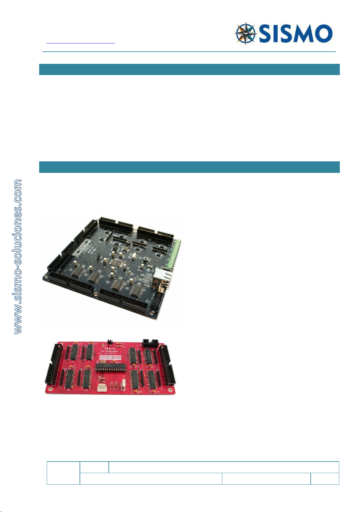
3FEATURES
Welcome to one of the boards of the SimCards family named SC-MB, specially designed for the control and
management of inputs and outputs of equipment and modules of simulators made or not by Sismo. Also
they can be used to any other system that requires to control a few elements on real time.
This new generation of electronic boards has meant a
new challenge for Sismo Soluciones, we have now
equaled the levels of technology, functionality and
benefits as those of the current professional industry.
The main feature of the board is that its’ connection
is made by means of an Ethernet bus, a standard
connection type in computer networks. This means
that it will be possible to connect to the equipment
to the control computer directly. Just as with an USB
2.0 bus but with the advantage that communications
and data transfer will be much more effective and
fast. These features are important for real time
systems such as simulators.
The Ethernet bus permits a centralization of the wires
of a network and it allows the option of extending it
and connecting the board to a Switch or Hub device.
Thanks to this, it also is possible to control the board
over long distances from the Internet and to do tests
of the hardware. It’s also possible to connect the
simulator via WIFI to a computer connected to the
local area network where the board is connected, this
represents a real revolution for flight simulators.
Another of the new characteristics and no less
important is that this board works as a “mother card”, and many daughter boards can be added, but
logically with a limit of inputs and outputs.
The type of connection is by means of a 10pin flat wire cable which can link the Mother board with all the
Daughter Boards in series; using connector CON_AUX. These connectors are a standard industrial type and
therefore they are also compatible with other boards or components.
Flight Simulators Solutions
www.sismo-soluciones.com
SC
1.4
SimCard Motherboard Ethernet and Daughterboards
User Manual
SC-MAN-SCE-E-10-0004
6 / 31
User Manual - SimCards Features - Rev1.4.docx
We have named the group formed by the Mother Board and the types of Daughter Boards which can be
connected to it: “the family of SimCards SC-MB boards”. The SC-MB Ethernet Family.
They are controlled by means of the programming language SC Pascal, the code it can be downloaded for
free. Nevertheless the SimCards are designed to be accessed by any other language so long as the board
has been previously configured.
For those who do not have any programming skills, but are enthusiastic about building a flight simulator,
we encourage you to visit our website and forum to search for programming examples, manuals and also
scripts for different flight simulation software.
4THE FAMILY OF SIMCARDS SC-MB BOARDS
ID
DESCRIPTION
SC-MB
SimCard Mother Board
SC-64DI-DB
SimCard 64 Digital Input Daugther Board
SC-64DO-DB
SimCard 64 Digital Output Daugther Board
SC-14SERV-DB
SimCard 14 Servos Daugther Board
SC-32DISP-DB
SimCard 32 Display Daugther Board
SC-10AI-DB
SimCard 10 Analog Input Daugther Board
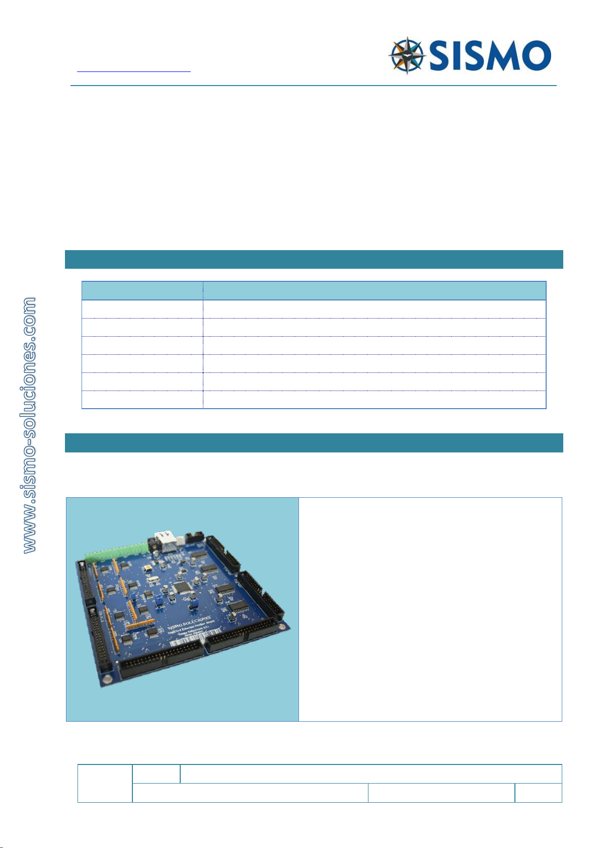
5KEY CHARACTERISTICS
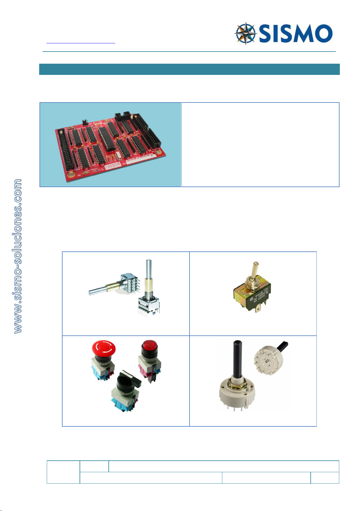
5.1 SIMCARD MOTHERBOARD (SC-MB)
Each SC-MB card comes with a 4 digit serial number,
you will need this number to configure the board and
to send to us if you need technical support.
The Mother Board is connected to the network by
means of an Ethernet port and can expand its
functionalities by means of Daughter Boards. The board
is connected to 5V DC.
The total inputs / outputs that it can control, are as
follows:
64 Digital Inputs. There are two IDC40 connectors.
64 Digital TTL Outputs. 2x IDC40. Io≈35mA each
one.
32 Displays of 7 segments in common cathode.
2 x IDC40.
5 Analog Inputs.
Flight Simulators Solutions
www.sismo-soluciones.com
SC
1.4
SimCard Motherboard Ethernet and Daughterboards
User Manual
SC-MAN-SCE-E-10-0004
7 / 31
User Manual - SimCards Features - Rev1.4.docx
There are two customizations of this product. You can choose to purchase the version with or without
displays. There is also an option of having the “Bottom pins” version, this has been designed to connect
directly to a backpanel and the connectors are located on the opposite side of the board.
An important concept to understand is that each pin of this board has been assigned a function. We follow
a contact map precisely so that the scripts we have written will work. If you want to use our scripts, and
thereby avoid programming, you must follow our contact maps, and connect everything accordingly.
5.2 DAUGHTER BOARDS YOU CAN CONNECT TO THE SC-MB
On the chart below there are represented how many Daughter boards you can connect:
ID
DESCRIPTION
Number of Daughter boards
I can connect
SC-64DI-DB
SimCard 64 Digital Input Daugther Board
2
SC-64DO-DB
SimCard 64 Digital Output Daugther Board
2
SC-14SERV-DB
SimCard 14 Servos Daugther Board
1
SC-32DISP-DB
SimCard 32 Display Daugther Board
2
SC-10AI-DB
SimCard 10 Analog Input Daugther Board
1
IMPORTANT NOTE: In the case of Input, output and display Daughter Boards, there can be two boards of
each type connected. Each Board must have a different name (e.g. SC-64DI1-DB and SC-64DI2-DB, or SC-
32DISP1-DB AND SC-32DISP2-DB). This is important if you purchase the daughter boards separately. If you
have two SC-IN1 boards being controlled by the same SC-MB, they will not work! To avoid this situation,
make a note of the number of the daughter card upon purchase.
5.3 DAUGHTER BOARDS REQUIRED FOR EACH PLUG&FLY MODULE
On the chart below there are indicated the number and the type of SC-Daughter necessary for any Plug&Fly
module.
PLUG & FLY
MODULE
SimCard Ethernet
Daughter Boards
Displays
No Displays
Inputs
Outputs
Displays
Servos
MIP
-
1
-
-
-
1
MCP & EFIS
1
-
1
-
-
-
FWD-Overhead
1
-
2
1
-
1
AFT-Overhead
1
-
1
-
-
1
Pedestal
1
-
1
-
2
1
Flight Simulators Solutions
www.sismo-soluciones.com
SC
1.4
SimCard Motherboard Ethernet and Daughterboards
User Manual
SC-MAN-SCE-E-10-0004
8 / 31
User Manual - SimCards Features - Rev1.4.docx
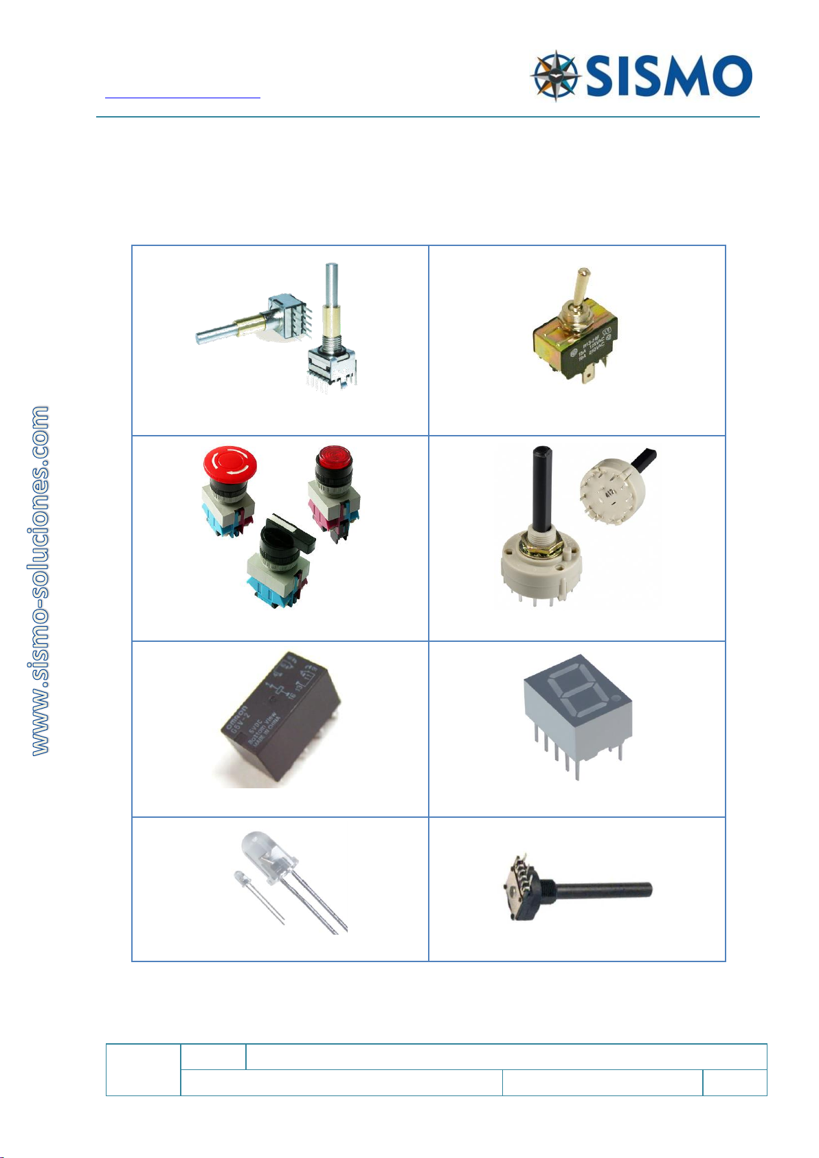
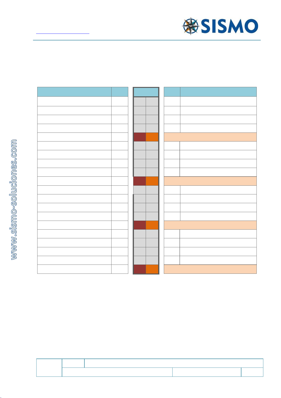
5.4 SUPPORTED COMPONENTS
The components which can be connected to this board are all kinds of switches, push-buttons, rotaries,
encoders, LEDs, displays, RELAYs, etc. The most common components are:
Rotary Encoders
Switch Buttons
Push Buttons
Rotary Switch
Relays
7 Segment Displays
LEDs
Analog Inputs (Potentiometers)
Flight Simulators Solutions
www.sismo-soluciones.com
SC
1.4
SimCard Motherboard Ethernet and Daughterboards
User Manual
SC-MAN-SCE-E-10-0004
9 / 31
User Manual - SimCards Features - Rev1.4.docx
5.5 WIRING SCHEDULE
The SC-MB is equipped with two IDC connectors of 40 pins for the inputs, DI1 and DI2; two IDC connectors
of 40 pins for Outputs, DO1 and DO2. There are also two IDC connectors with 40 pins for the Displays, DY1
and DY2.
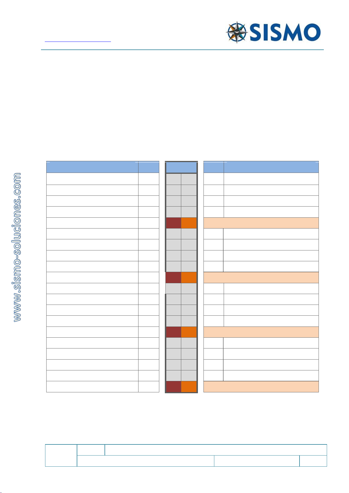
5.5.1 Inputs
5.5.1.1 DI1 controls inputs 1 to 32. All the grounds are common
Function
State
DI1
State
Function
Input 01
ON
1
2
ON
Input 02
Input 03
ON
3
4
ON
Input 04
Input 05
ON
5
6
ON
Input 06
Input 07
ON
7
8
ON
Input 08
+5V cc
9
10
GND
Input 09
ON
11
12
ON
Input 10
Input 11
ON
13
14
ON
Input 12
Input 13
ON
15
16
ON
Input 14
Input 15
ON
17
18
ON
Input 16
+5V cc
19
20
GND
Input 17
ON
21
22
ON
Input 18
Input 19
ON
23
24
ON
Input 20
Input 21
ON
25
26
ON
Input 22
Input 23
ON
27
28
ON
Input 24
+5V cc
29
30
GND
Input 25
ON
31
32
ON
Input 26
Input 27
ON
33
34
ON
Input 28
Input 29
ON
35
36
ON
Input 30
Input 31
ON
37
38
ON
Input 32
+5V cc
39
40
GND

Flight Simulators Solutions
www.sismo-soluciones.com
SC
1.4
SimCard Motherboard Ethernet and Daughterboards
User Manual
SC-MAN-SCE-E-10-0004
10 / 31
User Manual - SimCards Features - Rev1.4.docx
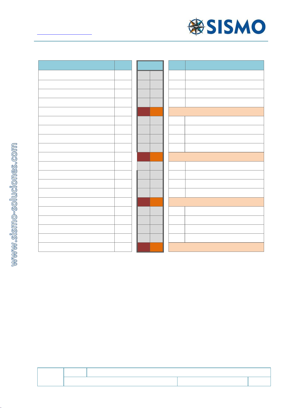
5.5.1.2 DI2 Controls inputs 33 to 64. All the grounds are common.
Function
State
DI2
State
Function
Input 33
ON
1
2
ON
Input 34
Input 35
ON
3
4
ON
Input 36
Input 37
ON
5
6
ON
Input 38
Input 39
ON
7
8
ON
Input 40
+5V cc
9
10
GND
Input 41
ON
11
12
ON
Input 42
Input 43
ON
13
14
ON
Input 44
Input 45
ON
15
16
ON
Input 46
Input 47
ON
17
18
ON
Input 48
+5V cc
19
20
GND
Input 49
ON
21
22
ON
Input 50
Input 51
ON
23
24
ON
Input 52
Input 53
ON
25
26
ON
Input 54
Input 55
ON
27
28
ON
Input 56
+5V cc
29
30
GND
Input 57
ON
31
32
ON
Input 58
Input 59
ON
33
34
ON
Input 60
Input 61
ON
35
36
ON
Input 62
Input 63
ON
37
38
ON
Input 64
+5V cc
39
40
GND

Flight Simulators Solutions
www.sismo-soluciones.com
SC
1.4
SimCard Motherboard Ethernet and Daughterboards
User Manual
SC-MAN-SCE-E-10-0004
11 / 31
User Manual - SimCards Features - Rev1.4.docx
5.5.2 Outputs
The Mother Board has a total of 64 outputs in a common cathode configuration which are distributed in
two connectors of 40 pins each.
The scheme of connection in common cathode format for the
connection of leds is shown in this image.
This means that the common part of all the outputs is the negative
(cathode).
5.5.2.1 DO1 Controls outputs from 1 to 32. All the grounds are common
Function
State
DO1
State
Function
Outputs 01
ON
1
2
ON
Outputs 02
Outputs 03
ON
3
4
ON
Outputs 04
Outputs 05
ON
5
6
ON
Outputs 06
Outputs 07
ON
7
8
ON
Outputs 08
+5V cc
9
10
GND
Outputs 09
ON
11
12
ON
Outputs 10
Outputs 11
ON
13
14
ON
Outputs 12
Outputs 13
ON
15
16
ON
Outputs 14
Outputs 15
ON
17
18
ON
Outputs 16
+5V cc
19
20
GND
Outputs 17
ON
21
22
ON
Outputs 18
Outputs 19
ON
23
24
ON
Outputs 20
Outputs 21
ON
25
26
ON
Outputs 22
Outputs 23
ON
27
28
ON
Outputs 24
+5V cc
29
30
GND
Outputs 25
ON
31
32
ON
Outputs 26
Outputs 27
ON
33
34
ON
Outputs 28
Outputs 29
ON
35
36
ON
Outputs 30
Outputs 31
ON
37
38
ON
Outputs 32
+5V cc
39
40
GND
Flight Simulators Solutions
www.sismo-soluciones.com
SC
1.4
SimCard Motherboard Ethernet and Daughterboards
User Manual
SC-MAN-SCE-E-10-0004
12 / 31
User Manual - SimCards Features - Rev1.4.docx
5.5.2.2 DO2 Connector is for outputs 33 to 64. All the grounds are common.
Function
State
DO2
State
Function
Output 33
ON
1
2
ON
Output 34
Output 35
ON
3
4
ON
Output 36
Output 37
ON
5
6
ON
Output 38
Output 39
ON
7
8
ON
Output 40
+5V cc
9
10
GND
Output 41
ON
11
12
ON
Output 42
Output 43
ON
13
14
ON
Output 44
Output 45
ON
15
16
ON
Output 46
Output 47
ON
17
18
ON
Output 48
+5V cc
19
20
GND
Output 49
ON
21
22
ON
Output 50
Output 51
ON
23
24
ON
Output 52
Output 53
ON
25
26
ON
Output 54
Output 55
ON
27
28
ON
Output 56
+5V cc
29
30
GND
Output 57
ON
31
32
ON
Output 58
Output 59
ON
33
34
ON
Output 60
Output 61
ON
35
36
ON
Output 62
Output 63
ON
37
38
ON
Output 64
+5V cc
39
40
GND

Flight Simulators Solutions
www.sismo-soluciones.com
SC
1.4
SimCard Motherboard Ethernet and Daughterboards
User Manual
SC-MAN-SCE-E-10-0004
13 / 31
User Manual - SimCards Features - Rev1.4.docx
5.5.3 Displays
The Mother Board has a total of 32 displays of 7 segments of common cathode
which are distributed in two 40 pins IDC connectors.
If you purchase the SC-MB without displays; DY1 and DY2 will be missing.
5.5.3.1 DY1 is a 40 pin connector which can control 16 displays of 7 segments. Named display
1 to 16. All the grounds are common.
Function
DY1
Function
GROUP 1 (8 displays)
Segment A
1
2
Segment B
Segment C
3
4
Segment D
Segment E
5
6
Segment F
Segment G
7
8
DP
Common GND
9
10
Common GND
Display1
11
12
Display2
Display3
13
14
Display4
Display5
15
16
Display6
Display7
17
18
Display8
Common GND
19
20
Common GND
GROUP 2 (8 displays)
Segment A
21
22
Segment B
Segment C
23
24
Segment D
Segment E
25
26
Segment F
Segment G
27
28
DP
Common GND
29
30
Common GND
Display9
31
32
Display10
Display11
33
34
Display12
Display13
35
36
Display14
Display15
37
38
Display16
Common GND
39
40
Common GND

Flight Simulators Solutions
www.sismo-soluciones.com
SC
1.4
SimCard Motherboard Ethernet and Daughterboards
User Manual
SC-MAN-SCE-E-10-0004
14 / 31
User Manual - SimCards Features - Rev1.4.docx
5.5.3.2 DY2 is a 40 pin connector which can control 16 displays of 7 segments. Named display
17 to 32. All the grounds are common.
Function
DY2
Function
GROUP 1 (8 displays)
Segment A
1
2
Segment B
Segment C
3
4
Segment D
Segment E
5
6
Segment F
Segment G
7
8
DP
Common GND
9
10
Common GND
Display17
11
12
Display18
Display19
13
14
Display20
Display21
15
16
Display22
Display23
17
18
Display24
Common GND
19
20
Common GND
GROUP 2 (8 displays)
Segment A
21
22
Segment B
Segment C
23
24
Segment D
Segment E
25
26
Segment F
Segment G
27
28
DP
Common GND
29
30
Common GND
Display25
31
32
Display26
Display27
33
34
Display28
Display29
35
36
Display30
Display31
37
38
Display32
Common GND
39
40
Common GND
Flight Simulators Solutions
www.sismo-soluciones.com
SC
1.4
SimCard Motherboard Ethernet and Daughterboards
User Manual
SC-MAN-SCE-E-10-0004
15 / 31
User Manual - SimCards Features - Rev1.4.docx
6DAUGHTERBOARDS
6.1 SIMCARD 64 DIGITAL INPUT DAUGHTER BOARD (SC-64DI-DB)
This board is connected by means of a flat cable of 10
wires to the Mother Board.
Each board has 64 digital inputs and 2 boards of this
type can be connected to the Mother Board.
The Mother Board can therefore manage up to 192
digital inputs when two boards are connected.
6.1.1 Supported Components
The components that can be connected up to this board are all kinds of switches, push-buttons, rotarys,
encoder, etc. The most habitual components are:
Rotary Encoders
Switch Buttons
Push Bottons
Rotary Switch
Flight Simulators Solutions
www.sismo-soluciones.com
SC
1.4
SimCard Motherboard Ethernet and Daughterboards
User Manual
SC-MAN-SCE-E-10-0004
16 / 31
User Manual - SimCards Features - Rev1.4.docx
6.1.2 Wiring Schedule
There are two 40-pin IDC Connectors on this board. The sockets are called DI1 and DI2. DI1 controls the
discreet inputs 1 to 32. DI2 controls inputs 33 to 64. All the grounds in these connectors are common.
6.1.2.1 DI1
Function
State
DI1
State
Function
Input 01
ON
1
2
ON
Input 02
Input 03
ON
3
4
ON
Input 04
Input 05
ON
5
6
ON
Input 06
Input 07
ON
7
8
ON
Input 08
+5V cc
9
10
GND
Input 09
ON
11
12
ON
Input 10
Input 11
ON
13
14
ON
Input 12
Input 13
ON
15
16
ON
Input 14
Input 15
ON
17
18
ON
Input 16
+5V cc
19
20
GND
Input 17
ON
21
22
ON
Input 18
Input 19
ON
23
24
ON
Input 20
Input 21
ON
25
26
ON
Input 22
Input 23
ON
27
28
ON
Input 24
+5V cc
29
30
GND
Input 25
ON
31
32
ON
Input 26
Input 27
ON
33
34
ON
Input 28
Input 29
ON
35
36
ON
Input 30
Input 31
ON
37
38
ON
Input 32
+5V cc
39
40
GND

Flight Simulators Solutions
www.sismo-soluciones.com
SC
1.4
SimCard Motherboard Ethernet and Daughterboards
User Manual
SC-MAN-SCE-E-10-0004
17 / 31
User Manual - SimCards Features - Rev1.4.docx
6.1.2.2 DI2
Function
State
DI2
State
Function
Input 33
ON
1
2
ON
Input 34
Input 35
ON
3
4
ON
Input 36
Input 37
ON
5
6
ON
Input 38
Input 39
ON
7
8
ON
Input 40
+5V cc
9
10
GND
Input 41
ON
11
12
ON
Input 42
Input 43
ON
13
14
ON
Input 44
Input 45
ON
15
16
ON
Input 46
Input 47
ON
17
18
ON
Input 48
+5V cc
19
20
GND
Input 49
ON
21
22
ON
Input 50
Input 51
ON
23
24
ON
Input 52
Input 53
ON
25
26
ON
Input 54
Input 55
ON
27
28
ON
Input 56
+5V cc
29
30
GND
Input 57
ON
31
32
ON
Input 58
Input 59
ON
33
34
ON
Input 60
Input 61
ON
35
36
ON
Input 62
Input 63
ON
37
38
ON
Input 64
+5V cc
39
40
GND
Flight Simulators Solutions
www.sismo-soluciones.com
SC
1.4
SimCard Motherboard Ethernet and Daughterboards
User Manual
SC-MAN-SCE-E-10-0004
18 / 31
User Manual - SimCards Features - Rev1.4.docx
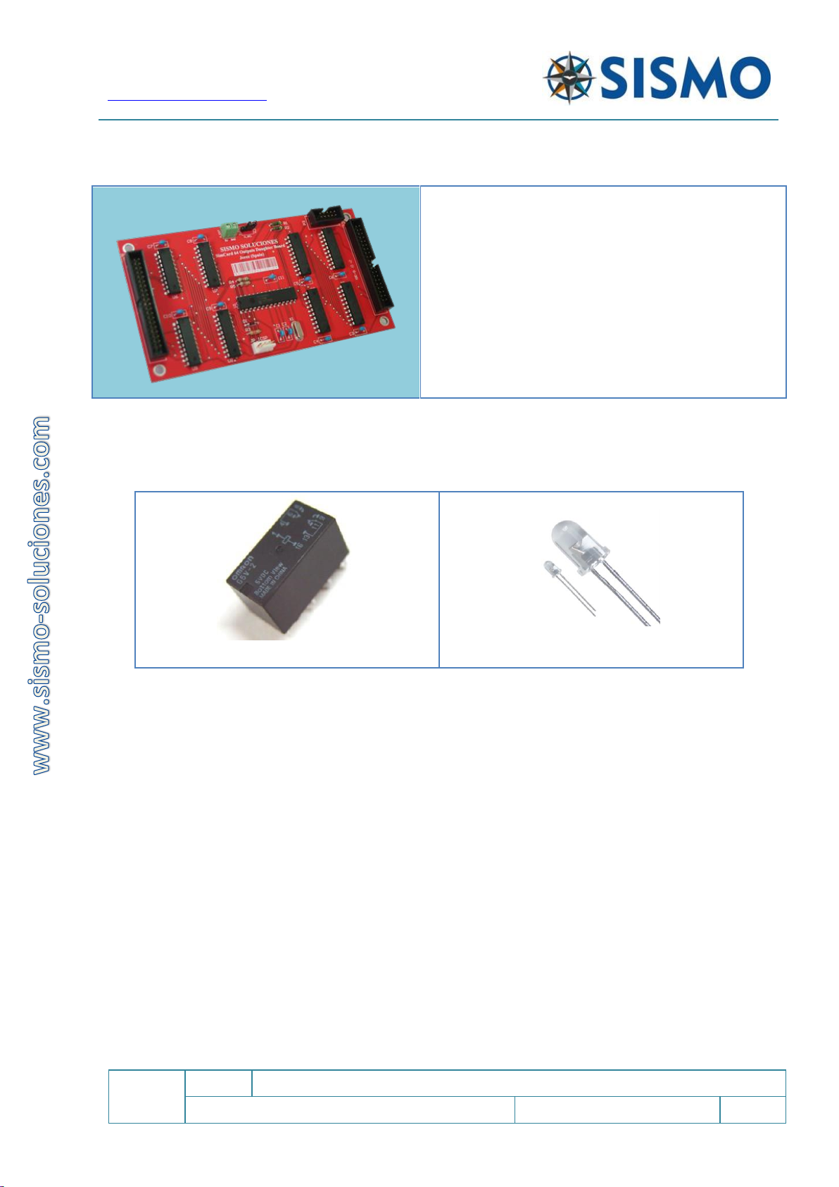
6.2 SIMCARD 64 DIGITAL OUTPUT DAUGHTER BOARD (SC-64DO-DB)
This board is connected by means of a flat cable of 10
wires to the Mother Board.
Each board has 64 digital outputs and 2 boards of this
type can be connected to the Mother Board.
The Mother Board can therefore manage up to 192
digital outputs when two boards are connected.
The Output board can be supplied by 5V through the
connector PWD (instead of through the SC-MB, which
is the default), this is intended to ensure that all the
components receive the same voltage.
6.2.1 Supported Components
The Most common components which are added are:
Reles
Leds
6.2.2 Wiring Schedule
There are two 40-pin IDC Connectors on this board. The sockets are called DO1 and DO2. DO1 controls the
discreet outputs 1 to 32. DO2 controls outputs 33 to 64. All the grounds in these connectors are common.

Flight Simulators Solutions
www.sismo-soluciones.com
SC
1.4
SimCard Motherboard Ethernet and Daughterboards
User Manual
SC-MAN-SCE-E-10-0004
19 / 31
User Manual - SimCards Features - Rev1.4.docx
6.2.2.1 DO1
Function
State
DO1
State
Function
Outputs 01
ON
1
2
ON
Outputs 02
Outputs 03
ON
3
4
ON
Outputs 04
Outputs 05
ON
5
6
ON
Outputs 06
Outputs 07
ON
7
8
ON
Outputs 08
+5V cc
9
10
GND
Outputs 09
ON
11
12
ON
Outputs 10
Outputs 11
ON
13
14
ON
Outputs 12
Outputs 13
ON
15
16
ON
Outputs 14
Outputs 15
ON
17
18
ON
Outputs 16
+5V cc
19
20
GND
Outputs 17
ON
21
22
ON
Outputs 18
Outputs 19
ON
23
24
ON
Outputs 20
Outputs 21
ON
25
26
ON
Outputs 22
Outputs 23
ON
27
28
ON
Outputs 24
+5V cc
29
30
GND
Outputs 25
ON
31
32
ON
Outputs 26
Outputs 27
ON
33
34
ON
Outputs 28
Outputs 29
ON
35
36
ON
Outputs 30
Outputs 31
ON
37
38
ON
Outputs 32
+5V cc
39
40
GND

Flight Simulators Solutions
www.sismo-soluciones.com
SC
1.4
SimCard Motherboard Ethernet and Daughterboards
User Manual
SC-MAN-SCE-E-10-0004
20 / 31
User Manual - SimCards Features - Rev1.4.docx
6.2.2.2 DO2
Function
State
DO2
State
Function
Output 33
ON
1
2
ON
Output 34
Output 35
ON
3
4
ON
Output 36
Output 37
ON
5
6
ON
Output 38
Output 39
ON
7
8
ON
Output 40
+5V cc
9
10
GND
Output 41
ON
11
12
ON
Output 42
Output 43
ON
13
14
ON
Output 44
Output 45
ON
15
16
ON
Output 46
Output 47
ON
17
18
ON
Output 48
+5V cc
19
20
GND
Output 49
ON
21
22
ON
Output 50
Output 51
ON
23
24
ON
Output 52
Output 53
ON
25
26
ON
Output 54
Output 55
ON
27
28
ON
Output 56
+5V cc
29
30
GND
Output 57
ON
31
32
ON
Output 58
Output 59
ON
33
34
ON
Output 60
Output 61
ON
35
36
ON
Output 62
Output 63
ON
37
38
ON
Output 64
+5V cc
39
40
GND
This manual suits for next models
6
Table of contents
 user manual")


