Sismo SC-MB User manual

SC-MB Ethernet Configuration
User Manual
SC-MAN-SCE-E-17-0003
Rev. 1.7
©2005-2021, Sismo Soluciones All rights reserved

Flight Simulation
www.sismo-soluciones.com
SC
1.7
SC-MB Ethernet Configuration
User Manual
SC-MAN-SCE-E-17-0003
2 / 23
User Manual - SC-MB Configuration - Rev1.7.docx
LOG
Rev.
Date
Description
1.1
April 2010
First Edition
1.2
February 2013
Changes
1.3
February 2014
Ethernet Version
1.4
July 2017
Modifications, FAQs.
1.5
October 2019
Updates
1.6
February 2020
Updates
1.7
April 2021
Updates
INDEX
1Definitions and acronyms..........................................................................................................................3
1.1 Definitions.........................................................................................................................................3
1.2 Acronyms ..........................................................................................................................................3
2Related documentation.............................................................................................................................4
3Purpose of this document .........................................................................................................................4
4Installation and Hardware Configuration..................................................................................................4
4.1 Previous requirements......................................................................................................................4
4.2 Hardware Configuration ...................................................................................................................5
5Software Configuration for Advanced Users.............................................................................................7
6Software Configuration For Beginners ......................................................................................................8
6.1 IP Addresses......................................................................................................................................8
6.1.1 How to find the IP address of your computer on Windows.......................................................10
6.1.2 How to change an IP address on your computer .......................................................................11
6.2 Configuration of the Motherboard.................................................................................................12
6.2.1 NETWORK CONFIG......................................................................................................................13
6.2.2 UDP CONFIG ...............................................................................................................................13
6.2.3 DAUGHTER BOARD CONFIG .......................................................................................................15
6.3 What if I want to use a different Network ID for personal reasons? .............................................16
7Typical Connection Layout (local network) .............................................................................................16
8Hardware test..........................................................................................................................................18
9FAQs.........................................................................................................................................................21

Flight Simulators Solutions
www.sismo-soluciones.com
SC
1.7
SC-MB Ethernet Configuration
User Manual
SC-MAN-SCE-E-17-0003
3 / 23
User Manual - SC-MB Configuration - Rev1.7.docx
1DEFINITIONS AND ACRONYMS
1.1 DEFINITIONS
Item
Definition
Switch and Hub Device
A device for connecting many Ethernet cables. For use when you want to connect
many Ethernet devices to a single computer.
SC Pascal
A programming language and a high-level editor/compiler. All script provided by
Sismo are programmed in this language. There are manuals for learning this
language on our website. You can also download the program from our website.
Crossed Ethernet Cable
Standard Ethernet Cable
A type of Ethernet cable used to connect a module directly to a computer.
If you are using a standard Ethernet cable, you should connect the module to a
Hub/Switch or to your Router (and not directly to the computer)
Mother –Daughter
Master –Slave board
Ethernet
Local area network data transfer protocol. An alternative to USB.
IOCP
Input/output completion port (IOCP) is an API for performing multiple
simultaneous asynchronous input/output operations in Windows.
FSUIPC
Flight Simulator Universal Inter-Process Communication. For controlling
asynchronous input/output operations in flight simulation.
UDP
A protocol within the TCP/IP protocol suite
DHCP
Dynamic Host Configuration Protocol, A protocol that provides a means to
dynamically allocate IP addresses to computers on a local area network. To be
deactivated or the IP addresses will change!
Script
A program which controls the SC-MB and allows the user to assign the functions of
one of the Plug&Fly Modules (AFT, FWD, etc.) to the Motherboard.
Add-on Company
ProSim, iFLy, PMDG. They are companies which interface the hardware with the
flight simulation software.
Autosense
a feature found in network adapters that allows them to automatically recognize
the current local network's speed and adjust its own setting accordingly
Plug&Fly Modules
Require no building or skills in electronics. They are fully equipped to be installed
on your simulator. They are the FWD, AFT, MIP, Pedestal, MCP and EFIS.
LAN
A local area network (LAN) is a collection of devices connected together in one
physical location, such as a building, office, or home.
1.2 ACRONYMS
Item
Definitions
PCB
Printed Circuit Board.
SC-MB
SimCard Ethernet Motherboard.
SC-Daughter
SimCard Ethernet Daughter. It is a daughter or slave card, complementary to the SC-MB.

Flight Simulators Solutions
www.sismo-soluciones.com
SC
1.7
SC-MB Ethernet Configuration
User Manual
SC-MAN-SCE-E-17-0003
4 / 23
User Manual - SC-MB Configuration - Rev1.7.docx
2RELATED DOCUMENTATION
Ref
DOCUMENT
Revision
SC-MAN-SCE-E-10-0004
User Manual - SimCards Features
Last (web)
ELEC-DSH-SCE-E-10-0001
Datasheet - SimCards Ethernet UDP Protocol
Last (web)
Programming with SC-Pascal –Vol I
Please get in touch
Programming with SC-Pascal –Vol II
Please get in touch
FS Connection Layout
Please get in touch
S737-REP-CFG-E-18-0019
User Guide –ProSim Configuration and Technical Report -
Using Prosim737 v2 with Sismo Modules Ethernet - Rev1.2
Last (web)
FS-MAN-SOF-NA-E-20-2453
OrbitXP Connector for X-Plane11
Last (web)
3PURPOSE OF THIS DOCUMENT
To describe the method of configuration of Simcard Motherboards.
Any client who owns an SC-MB, or a product which contains one (including the Plug and Fly Modules), must
read this manual in order to configure their modules.
In this manual you will find all the information you need to have your Simcard working and configured on SC-
Pascal.
4INSTALLATION AND HARDWARE CONFIGURATION
4.1 PREVIOUS REQUIREMENTS
The SimCard Motherboards are compatible with every operating system;
the only requirement is to have a computer with a free Ethernet port. And
even this isn’t much of a limitation thanks to devices called HUBs or
SWITCHES which allow you to centralize the wiring of Ethernet cables of a
network and to increase the number of available ports.
There are two ways of connecting the Mother Board to the control
computer:
1. Directly with a single cable: in this case you must use a crossed
Ethernet cable to connect the Mother Board with the computer.
2. By means of a Switch or Hub: here you can use a crossed cable or a standard Ethernet cable
indistinctly.
The Motherboard is usually connected to the computer where the flight simulation software (e.g. Prepar3D,
FSX) is installed, because it must access its functions through IOCP or FSUIPC communication protocol. We
recommend this approach, it is not obligatory, but the steps required to do otherwise are outside the scope
of this manual.

Flight Simulators Solutions
www.sismo-soluciones.com
SC
1.7
SC-MB Ethernet Configuration
User Manual
SC-MAN-SCE-E-17-0003
5 / 23
User Manual - SC-MB Configuration - Rev1.7.docx
Other recommendations:
1. Download the latest free Build of the SC-Pascal editor/compiler (download section from Sismo
Web). A powerful hardware testing tool.
2. With older versions of our products, you may need to install the latest version of “FSUIPC” for
FSX or P3D. More info at: http://www.schiratti.com/dowson.html. Please refer to the User Manual
of your chosen Add-on. If you are using a native configuration with ProSim or OrbitXP, you don’t
need to download FSUIPC.
4.2 HARDWARE CONFIGURATION
Once you have connected the SC-MB to
the control computer by means of a
crossed cable or a HUB device, proceed to
supply current to the Ethernet SC-MB
Mother Board.
Optional Note: It is recommended to have
the rest of hardware and computers
disconnected from the network for
configuring the Board.
The terminals of the board must receive a
voltage of 5V DC.
A lower voltage is not enough for the Motherboard to work correctly and a higher voltage can damage the
servos which may be connected to the Motherboard.
There are two possible ways to connect 5V to the board. The black connector inside the red circle in the
picture below or the green connector immediately to the right. They are designed in parallel, and you only
need to connect one of them.
If you have the option of using the black connector (DC_CON), make sure you don’t connect 12V to the board.

Flight Simulators Solutions
www.sismo-soluciones.com
SC
1.7
SC-MB Ethernet Configuration
User Manual
SC-MAN-SCE-E-17-0003
6 / 23
User Manual - SC-MB Configuration - Rev1.7.docx
Otherwise, please follow the steps detailed below:
IMPORTANT:The Board might be
affected if the positive and negative
terminals are not as shown on screen.
For those users who do not want to use
the green threaded terminals, it is
possible to supply the Board through a
connector qualified to do it (DC_CON).
Inner pin is “+” and outer is GND/COM.
For safety, also check with a
multimeter that the voltage in the
terminals of the scheme is 5V CC.
In the SC-MB Simcards family. There are 4 types of JUMPERS. Each one has a specific function.
When purchasing the Board, the user will find the jumpers properly located in their places by default. The
advice is not to change the place of the jumpers and do not remove it unless the user has a definite need to
do so.
For those who may be interested, the table below shows the function of each jumper.
The jumpers JP_PGC and JP_PGD must always
be placed, because they manage the
programming of the chip of the Mother Board
and if they were removed, the Board would
stop working.

Flight Simulators Solutions
www.sismo-soluciones.com
SC
1.7
SC-MB Ethernet Configuration
User Manual
SC-MAN-SCE-E-17-0003
7 / 23
User Manual - SC-MB Configuration - Rev1.7.docx
Similarly, if the JP1 jumper is removed, the
inputs of the Board would be disabled. The JP1
jumper provides the possibility of selecting the
desired logic for the Inputs, that is to say, if we
change the cover of the jumper from the 1-2
pins to the 2-3 pins, the logic will be reversed in
one way or another, as is convenient for the
user. This type of jumper can be located on the
Mother Board and on the Input Daughter
Boards.
The JP2 jumper, is only found on the Mother
Board. It must always be placed between the
central pin and +5V.
The advice now is to visually inspect that the jumpers are located in the correct place to ensure the optimum
performance of the Board.
5SOFTWARE CONFIGURATION FOR ADVANCED USERS
In the following section, we will briefly describe the steps for the software configuration for users who have
some knowledge of Ethernet systems. If you are a beginner, head to section 6.
1. Set a static IP address.
Go to Networks>properties>Internet protocol IPv4>properties. Define an IP address, for example
192.168.1.101 this is your control computer IP. Leave the automatic Subnet Mask value. In the third
box you must write an IP with the same Network ID: 192.168.1.1.
2. Type the IP address SC-MB into your usual internet browser (192.168.1.150 BY DEFAULT). The
CONFIG PAGE will appear.

Flight Simulators Solutions
www.sismo-soluciones.com
SC
1.7
SC-MB Ethernet Configuration
User Manual
SC-MAN-SCE-E-17-0003
8 / 23
User Manual - SC-MB Configuration - Rev1.7.docx
3. Under NETWORK CONFIG: the IP ADDRESS is the IP address of the SC-MB (192.168.1.150 by default).
Leave the value of MASK as it is and for DEFAULT GATEWAY leave 192.168.1.1. Press SAVE BOARD
CONFIG.
4. UDP CONFIG is the control computer information. HOST IP is the address for the control computer.
Leave LOCAL PORT default value of 1024 and the HOST PORT value of 1026. Press SAVE BOARD
CONFIG.
5. Only activate the daughter boards you have connected or it will slow down your computer. Press
SAVE DAUGHTER CONFIG.
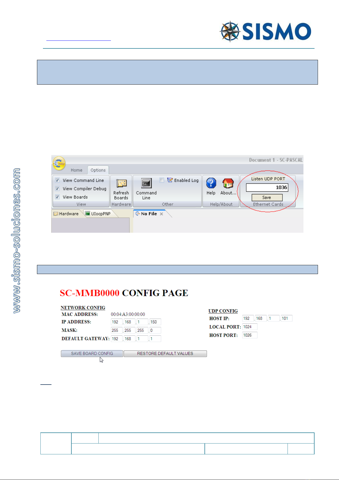
6. Open SC-Pascal (You can download it on our website). Go to the options tab. In the box: Listen UDP
PORT. Make sure the HOST PORT number is the same as the configuration page.
7. You will see the name of your SC-MB card appear in SC-Pascal.
8. See information below for testing the hardware.
6SOFTWARE CONFIGURATION FOR BEGINNERS
Sismo’s Ethernet Boards work in a Local Area Network (LAN). Every device in a LAN has an IP address, it looks
like this: 192.168.1.150
IP addresses are divided into Network ID (first three fields) and Host ID (last field). In a LAN, every device
must have the same Network ID and a different Host ID.
The default Network ID we use in all of our SC-MBs is 192.168.1.
There are three scenarios for configuration of the SC-MB:
1- Your LAN and Control computer already have the same Network ID as our default (192.168.1). In this
case, the SC-MB will automatically be recognised. Find the IP address of your control computer in
step 6.1.1.
2- Your LAN and Control computer have a different Network ID than our default. You are happy to
change your LAN to our default Network ID. Learn how to change the IP address of your computer
in 6.1.2.
3- Your LAN and Control computer have a different Network ID than our default. You want to keep the
Network ID you are currently using. An example is found in section 6.3.
6.1 IP ADDRESSES
The default IP Address of the Motherboard will depend on whether you purchase it on its own, or whether
the SC-MB you are configuring is inside a Plug and Fly Module. Below, a table showing the default IP address
of the 737NG and the 737MAX Plug&Fly Modules
This Information is important for the initial configuration. The IPv4 address has four fields. The first three
fields of the IP addresses (called octets), in red, represent the Network ID of the network. The final field
represents the Host ID.

Flight Simulators Solutions
www.sismo-soluciones.com
SC
1.7
SC-MB Ethernet Configuration
User Manual
SC-MAN-SCE-E-17-0003
9 / 23
User Manual - SC-MB Configuration - Rev1.7.docx
B737 NG:
MODULE
DEFAULT IP
HOST PORT
Default
192.168.1.150
1026
MCP-EFIS
192.168.1.151
1151
MIP
192.168.1.152
1152
PEDESTAL
192.168.1.153
1153
FWD-OH
192.168.1.154
1154
AFT-OH
192.168.1.155
1155
B737 MAX:
MODULE
DEFAULT IP
HOST PORT
Default
192.168.1.150
1026
MCP-EFIS
192.168.1.171
1171
MIP
192.168.1.172
1172
PEDESTAL
192.168.1.173
1173
FWD-OH
192.168.1.174
1174
AFT-OH
192.168.1.175
1175
PEDESTAL 2*
192.168.1.176
1176
2* With an additional SimCard to make the Fire
Suppression Panel functional
This Information is important for the initial configuration. The IPv4 address has four fields. The first three
fields of the IP addresses (called octets), in red, represent the Network ID of the network. The final field
represents the Host ID.
The IP of the computer (and the network) must have the same Network ID as the SC-MBs.
Below is a basic diagram showing the necessary components for the configuration of a simple network using
one computer (Notice the Network ID):
The Network ID of the control computer is the same as the Motherboard’s, this is a necessary condition for
network connectivity.
Note: It’s essential to disable the DHCP on the computers that you are going to connect with SC-Pascal scripts
to avoid IP address conflicts.

Flight Simulators Solutions
www.sismo-soluciones.com
SC
1.7
SC-MB Ethernet Configuration
User Manual
SC-MAN-SCE-E-17-0003
10 / 23
User Manual - SC-MB Configuration - Rev1.7.docx
Due to the fact that the Motherboard has a Network ID of 192.168.1 by default, the first step for the
configuration is to check that the IP address of the control computer also has a Network ID of 192.168.1.
6.1.1 How to find the IP address of your computer on Windows
Hit the Windows home button on your toolbar.
Type “cmd”. Select “Open” or <Enter> to open the Command Prompt.
Type in the command: “ipconfig”. That will return the data on your computer IP address.
-

Flight Simulators Solutions
www.sismo-soluciones.com
SC
1.7
SC-MB Ethernet Configuration
User Manual
SC-MAN-SCE-E-17-0003
11 / 23
User Manual - SC-MB Configuration - Rev1.7.docx
The numbers inside the green box represent the IP address and the Subnet mask. The yellow box is for your
Network ID.
If the IPv4 address on your control computer has a Network ID of 192.168.1, we don’t need to change the IP
address.
6.1.2 How to change an IP address on your computer
When a change of IP is necessary due to having a different Network ID, the user must temporarily change
the IP address of his control computer to the Network ID of 192.168.1 so that the card can be connected to
the computer for the first time (again, this is because the SC-MB has a Network ID of 192.168.1 by default)
*We have used Windows 10 for this example:
1. Go to: Start > Control Panel > Network and Sharing Centre > Change adapter settings
2. Select the icon which appears and right click. Open the properties window.
3. Double click on “Internet protocol v4 (TCP/IPv4)”
4. Again, a new window is opened. Mark the option "Use the following IP Address" to activate the text
boxes below and insert a new IP address (Ej: IP address 192.168.1.101).
5. As “subnet mask” to write for example 255.255.255.0 and in the third field 192.168.1.1
Note1: The process to reach the IPv4 connection may vary slightly between operating systems. Tutorials are
easily found on the internet for other operating systems, nevertheless there is a screenshot of the same
procedure for Windows 10 in English below.
Once you press OK on the pop-up window, the changes have been saved.

Flight Simulators Solutions
www.sismo-soluciones.com
SC
1.7
SC-MB Ethernet Configuration
User Manual
SC-MAN-SCE-E-17-0003
12 / 23
User Manual - SC-MB Configuration - Rev1.7.docx
1. It will now be possible for the Control Computer and the Motherboard to communicate, and now we
must configure the board.
This provisional change in the IP address does not pose a problem for the configuration of the rest of the
modules that the user has done previously, because once we access the configuration page of this
equipment, it will be possible to restore the previous IP addresses as well as give a new IP address to the
Mother Board with the Network ID that the user has used in the network.
6.2 CONFIGURATION OF THE MOTHERBOARD
The next step is to make sure that the ports and IP addresses are compatible and that the computer and the
Motherboard can communicate. There is a CONFIG PAGE where we can do all these operations. To access it,
open your usual internet browser (internet explorer, chrome, etc.) and type in the IP Address of the
Motherboard on the address bar. In this example, a default Motherboard which is not from a Plug&Fly
Module.
http://192.168.1.150/
(How do I know this? See 6.2 IP addresses above).
This is the page that loads:
*The number in red represents the serial number of your SC-MB card (in this case 0000).

Flight Simulators Solutions
www.sismo-soluciones.com
SC
1.7
SC-MB Ethernet Configuration
User Manual
SC-MAN-SCE-E-17-0003
13 / 23
User Manual - SC-MB Configuration - Rev1.7.docx
The serial number is necessary for configuring SC-Pascal and for connecting the scripts (software used to
communicate with add-on companies like ProSim or iFly).
Whenever you make a change to the board, you must either hit “Save board/daughter config” or refresh the
page with f5 or the refresh symbol.
As you can see, there are three fields of data: NETWORK CONFIG, UDP CONFIG and DAUGHTER BOARDS
CONFIG. We’ll look at each separately for simplicity:
6.2.1 NETWORK CONFIG
MAC ADDRESS: is the hardware address of the Mother Board, it is unique and cannot be modified. The last
four digits are in hexadecimal and give name to the variable part of the serial number of the equipment. The
invariable part is fixed as SC-MB: SC-MBnnnn
IP ADDRESS: This represents the IP address of the SC-MB card. This will be 198.168.1.150 for a standalone
SC-MB. You are free to change this number if you wish, but remember that the Network ID of the IP addresses
in the network must be the same for communication to be possible. We recommend not changing the default
IP addresses of Plug&Fly modules because it will affect native configuration with ProSim and OrbitXP.
Note1: the new assigned Host ID in the IP address of the Mother Board must not be repeated in any other
hardware or equipment of the network, otherwise it will create conflict and will not load correctly. It you
forgot this instruction; you must reset the board to factory settings.
Note2: When you change this IP address, you must refresh the page. Remember that the number you must
type in the “http” bar in your browser will also have changed.
MASK: in this section, we suggest you use the same number that you have used in the control computer of
the network. By default, it is: 255.255.255.0
DEFAULT GATEWAY: it can be used to send information through Internet. If you are not going to use it, leave
the default value: 192.168.1.1 (for more info ask Sismo Support).
6.2.2 UDP CONFIG
HOST IP: is the IP address of the control computer. This must have the same Network ID as the Motherboard.
Any value inside the Network ID of 192.168.1 is suitable to use.
LOCAL PORT: If you are using Sismo’s scripts or native configurations,
leave the default value of 1024.
*This port can be modified for those who want to use their own editor/compiler and
not SC-Pascal, because the LOCAL PORT is the port where the Mother Board receives
the data from the control computer.
HOST PORT: is the port where the control computer is going to get the information from the Mother Board.
The default port depends on the Plug&Fly module. Consult table in 6.1.
Flight Simulators Solutions
www.sismo-soluciones.com
SC
1.7
SC-MB Ethernet Configuration
User Manual
SC-MAN-SCE-E-17-0003
14 / 23
User Manual - SC-MB Configuration - Rev1.7.docx
The default host port changes for every Plug&Fly module. Do not change the Host Port if you are using a
native configuration with ProSim or OrbitXP. These software solutions use this Host Port by default. If you
have to change it, consult the add-on manual.
This port must remain open and unused by any other program in order for the data to be received.
If the port is occupied, another must be chosen (Any four-digit number excluding those already in use). In
this case, review the add-on manual.
SC-Pascal V5 Build 765 or superior allows to the user to change the Host Port in the field "Listen UDP Port".
In order for this equipment and SC-Pascal to communicate, the HOST PORT indicated in the CONFIG PAGE in
and the port where SC-Pascal listens, which is indicated in "Listen UDP Port ", must be the same.
*In this example, the HOST PORT was changed to 1036, but the default value of the port should be left.
Once all the fields in Network Config and UDP Config have been filled out, remember to press SAVE BOARD
CONFIG to store the information.
Note: Wait at least 5 seconds while the data is saved on the Internet browser.
It is necessary to close and reopen the browser to ensure the storage of the new data. Remember that the
new IP Address of the Motherboard should now be written in the “Http” search bar. You’ll now be able to
see the updated configuration. If everything is correct, head to section 6.2.3.
If you need to modify any of the information in Network Config or UDP Config, at a later time or due to any
mistakes, this will not present a problem. The only consideration is that you must “Save Board Config” and
close and reopen the browser to make sure the new information has been saved.

Flight Simulators Solutions
www.sismo-soluciones.com
SC
1.7
SC-MB Ethernet Configuration
User Manual
SC-MAN-SCE-E-17-0003
15 / 23
User Manual - SC-MB Configuration - Rev1.7.docx
If for whatever reason, you believe it would be better to restart the
configuration from scratch, you have two options. The first is to press the
button RESTORE DEFAULT VALUES on the CONFIG PAGE.
You could also open the back-metal cover of the Motherboard and press the
physical RESET button for at least 10 seconds. For this to have any effect, the
SC-MB must be connected to a power supply.
Both of these methods erase the EEPROM (Electrically Erasable Programmable
Read-Only Memory).
6.2.3 DAUGHTER BOARD CONFIG
In this field, we must indicate the Daughters Boards which are going to be connected to the Mother Board.
We can select as many as we wish, even if they are not connected, however this will slow down data
processing speed. We advise you select only the Daughters Boards which are connected to the Mother Board.
The CONFIG PAGE allows the activation of a total of 2 Inputs
Daughters Boards, 2 of Outputs, 1 of Displays, 1 of Servos and 1
ADC (pots). These are considered sufficient to manage most
systems.
Pressing SAVE DAUGHTER CONFIG is enough for the information to
be stored. It isn’t necessary to restart the browser for the daughter
configuration to be saved.
You will not need to revisit the CONFIG PAGE unless you want to
make a specific change to the configuration. For example, if you
purchase another daughter board you wish to connect.
Note: if the CONFIG PAGE has difficult loading throughout the configuration, don’t worry, it is slow because of the
internet protocol. If the CONFIG PAGE is too slow or fails to load, try reloading the CONFIG PAGE on a new browser.
You can also remove the power supply and start the configuration from the beginning.
The following table shows the daughter boards that must be active for each module.
MODULE
MCP-EFIS
MIP
Pedestal
FWD
AFT
MAX Pedestal
SC-MDODB OUTPUTS1
ON*
ON
ON
SC-MDODB OUTPUTS2
SC-MDIDB INPUT1
ON
ON
ON
ON
SC-MDIDB INPUT2
ON*
ON
ON
SC-MSDB SERVOS
ON
ON
ON
ON
ON
SC-MDDB DISPLAYS1
ON
ON
SC-MDDB DISPLAYS2
ON
ON
SC-MAIDB ADCS

Flight Simulators Solutions
www.sismo-soluciones.com
SC
1.7
SC-MB Ethernet Configuration
User Manual
SC-MAN-SCE-E-17-0003
16 / 23
User Manual - SC-MB Configuration - Rev1.7.docx
* These daughter boards only need to be ON if you are using the Pedestal Electronic Baseplate V3.
6.3 WHAT IF I WANT TO USE A DIFFERENT NETWORK ID FOR PERSONAL REASONS?
For this example, we assume that you have read section 6 completely.
If you are using a different Network ID than 192.168.1 in your LAN and you don’t want to change it for
personal reasons, such as having previously configured other devices in your LAN, please follow these steps:
1. As an example, let’s say your control computer has the following IP address: 192.168.2.200.
2. To access the CONFIG PAGE of your SC-MB, the IP address of the control computer must have the same
Network ID as the Mother Board. Therefore, we must proceed to temporarily change the IP address of
the computer to 192.168.1.200. Remember the IP of your computer, in order to change it back later.
3. Then we can access the CONFIG PAGE of the SC-MB. Enter the IP address for the SC-MB in your browser.
E.g. http://192.168.1.150/.
4. Only now are we able to change the default IP of the Mother Board to the target Network ID of
192.168.2.150.
5. Reset the IP address of the control computer back to the one that the user had before (or any other
desired IP in the Network ID).
6. Test that your computer has communication with the SC-MB by typing the new IP address into your
browser: http://192.168.2.150/. The CONFIG PAGE should appear.
7TYPICAL CONNECTION LAYOUT (LOCAL NETWORK)
This is an example of a network configuration
composed by 2 computers which control and
manage 2 Mother Boards. Components and Plug
Ready Modules (SISMO PRMs) are also connected
to the Mother Board. There are two configuration
options for this scenario:
a) One of the computers controls both
Motherboards
b) Each computer controls a single
Motherboard
The sole requirement for the network connectivity
is that the 4 elements have the same Network ID in
their IP Addresses. For example:
192.168.1.150 (Mother Board 1)
192.168.1.151 (Mother Board 2)
192.168.1.152 (computer 1)
192.168.1.153 (computer 2)

Flight Simulators Solutions
www.sismo-soluciones.com
SC
1.7
SC-MB Ethernet Configuration
User Manual
SC-MAN-SCE-E-17-0003
17 / 23
User Manual - SC-MB Configuration - Rev1.7.docx
Every SC-MB and Computer has at least one Ethernet Port. We will use these to connect to the local
network.
In the case of having four elements to the Network (two SC-MB and two computers), each of these must be
connected via an Ethernet cable to a SWITCH; HUB or ROUTER (with a program called Autosense). This
connection will permit communication between the modules.
You can also connect the internet directly to the SWITCH, that
way the whole network will have access to it.
Switch Autosense
Here is another example of a Network:

Flight Simulators Solutions
www.sismo-soluciones.com
SC
1.7
SC-MB Ethernet Configuration
User Manual
SC-MAN-SCE-E-17-0003
18 / 23
User Manual - SC-MB Configuration - Rev1.7.docx
Next Steps
Once the network has been set-up, you will then proceed to open SC-Pascal.
At this point, we recommend you go to the next step and perform a hardware test. This will allow you to
verify that all of the components, lights, pots etc. are working correctly.
There is the added benefit that if you perform this task, and the hardware is working correctly, you can
immediately determine that any problem you encounter later is due to software or configuration, thus
making your troubleshooting process easier.
Once this step has been done, we suggest you search for the User Manual for your chosen Add-on software
(i.e. ProSim or iFly).
8HARDWARE TEST
Sismo Soluciones has used SC-Pascal programming language for its development. This board can be
controlled with any programming language given a previous configuration of the board (see jumpers section
above), however, in this manual we concern ourselves exclusively with the necessary requirements to control
the board with the SC-Pascal editor/compiler, and this solution will be fully adequate for users who are
interacting with a flight simulator.
One of the benefits of SC-Pascal is that it has a section for the checking of the Hardware, including Inputs,
Outputs, Displays, Servos and Adc’s for both the Mother and Daughters Boards. Thus, the user can check the
active inputs at any given time, manually adjust the activated pins, check whether the displays are functional,
verify the servos and ADCs, find out whether the Outputs are really deactivated, etc.
In the table below, when we say “check” or “test” the hardware, we are asking you to verify that the software
(or SC-Pascal) is doing the same as your Hardware. For example, if we test an output on SC-Pascal, we should
be able to see some results on our Hardware.
Download the latest version of SC Pascal V5.1 Build 765 or superior which is
available in the download section of our website www.sismo-soluciones.com.
*We have manuals on learning the SC-Pascal programming language available to users on the
website.

Flight Simulators Solutions
www.sismo-soluciones.com
SC
1.7
SC-MB Ethernet Configuration
User Manual
SC-MAN-SCE-E-17-0003
19 / 23
User Manual - SC-MB Configuration - Rev1.7.docx
Screen 1: SC-Pascal
Launch SC-Pascal V5 by clicking
on the SC-Pascal Logo and the
following screen will appear.
In the left part you will see the
serial number of the
Motherboard (in blue) and all the
Daughters Boards (Below) which
you have activated on the
CONFIG PAGE.
This is only an example, the serial
number which appears is not
relevant.
For launching the application
"Hardware test", double click on
the serial number of the
Motherboard or on any of the
Daughters Boards which are
connected and configured.
Color Code:
ON -> green
OFF -> grey
Last active Input -> red

Flight Simulators Solutions
www.sismo-soluciones.com
SC
1.7
SC-MB Ethernet Configuration
User Manual
SC-MAN-SCE-E-17-0003
20 / 23
User Manual - SC-MB Configuration - Rev1.7.docx
Screen 2: Mother Board
With double click on the Mother
Board the user will be able to
observe:
The INPUTS’state (ON/ OFF).
You can activate or deactivate an
output by clicking on the number
corresponding to the OUTPUTS.
On this page you can also check
the 5 analogical inputs or pots.
Tick the box "ACTIVATE ADCn"
They are organized in rows of
eight because that is the number
of functional pins available, the
other two in a 10-pin connector
are the GND and +5v cc.
Therefore 64 inputs represent
two 40 pin connectors.
Screen 3: Mother Board
The following screen appears if
the user clicks on TEST DISPLAYS.
We can mark the orange
segments of the displays to verify
that they work adequately as well
as to change the
intensity/brightness or activate/
deactivate a concrete display by
clicking on the corresponding
number of each display.
This manual suits for next models
1
Table of contents


