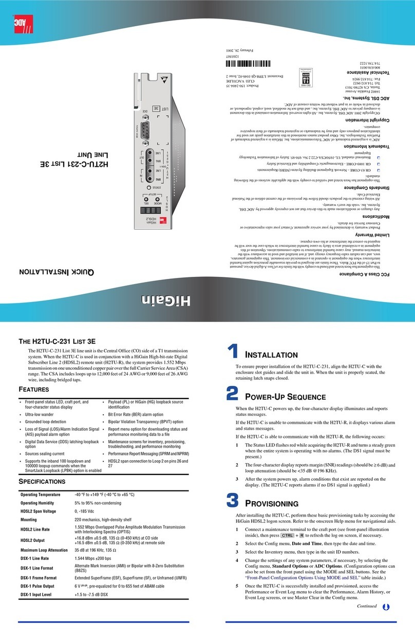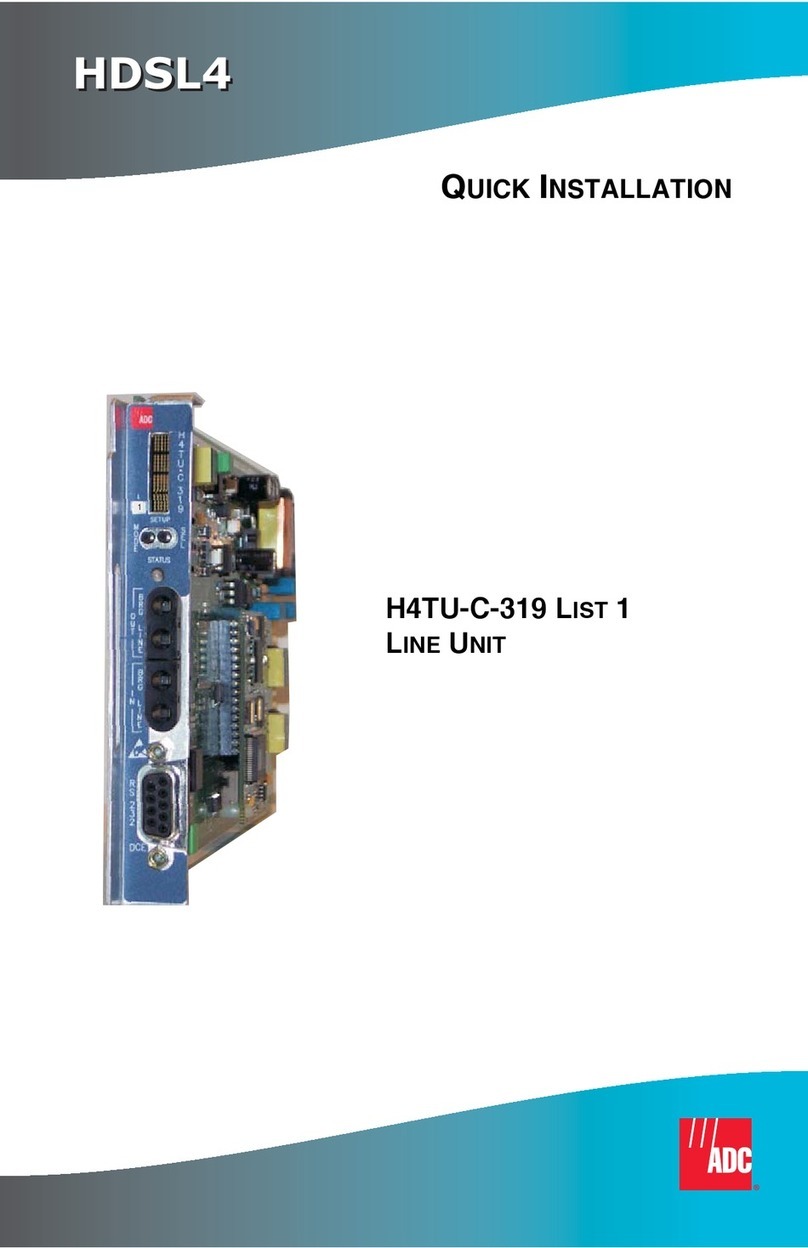
THE H4TU-C-231 LIST 5A
The H4TU-C-231 List 5A line unit is the Central Office (CO) side of a T1
transmission system. The H4TU-C, when usedwith an H4TU-Rremoteunit, transmits
a 1.544 Mbps payload a maximum distance of 12 kft. over two unconditioned copper
pairs. The H4TU-C supports three powered spans to further expand reach.
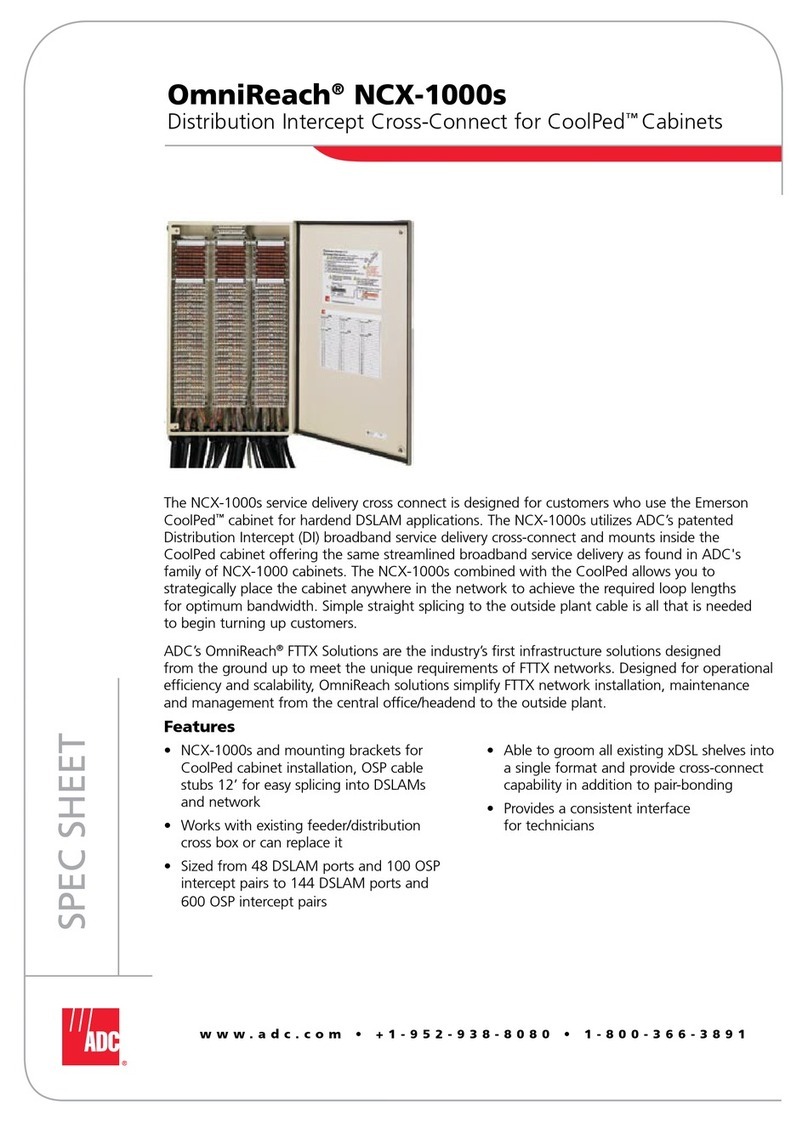
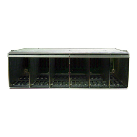
The H4TU-C-231 List 5A is designed to mount in 220 mechanics shelves.
FEATURES
SPECIFICATIONS
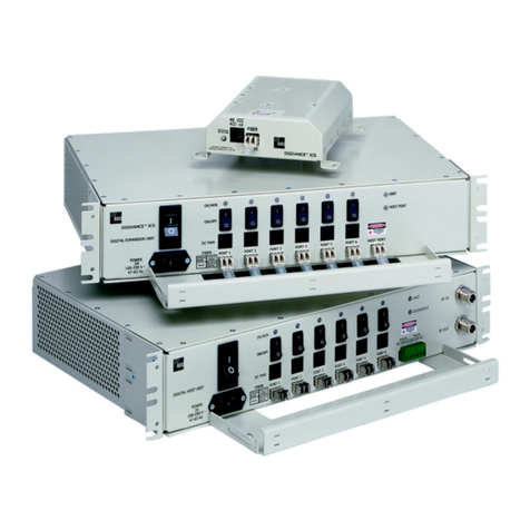
Front-panel features: craft port for maintenance
screen access, seven LEDs for system status
reporting, and DSX-1 access jacks
HDSL4 transmission features:
•Doubler (H4D) support for up to three spans
•Grounded loop and loop reversal detection
•Sources sealing current when connected to
locally powered H4TU-R-402 remote unit
•Digital Data Service (DDS) latching loopbacks
•Fractional T1 maintenance
Maintenance screens: for inventory,
provisioning, performance monitoring, and
troubleshooting, including:
•Remote provisioning
•Loop attenuation and insertion loss reporting
•Power Back Off feature configures HDSL4
transmit power levels to reduce crosstalk
•Report menu for downloads of status and
performance data
Operating Temperature -40°F to +149°F (-40°C to +65°C)
Operating Humidity 5% to 95% non-condensing
HDSL4 Span Voltage 0, -185 Vdc (Voltage is applied across Loop 1 and Loop 2.)
CO Supply -48 Vdc nominal (-42.5 Vdc to -56.5 Vdc)
Mounting 220 mechanics shelves
HDSL4 Line Rate 784 kbps Overlapped Pulse Amplitude Modulation (OPAM)
transmission per pair
HDSL4 Output +14.1 dBm ±0.5 dBm, 135Ω
Maximum Insertion Loss Span 1 = 47 dB at 196 kHz
Span 2 and Span 3 = 43 dB at 196 kHz
Maximum Loop Attenuation Span 1 = 31 dB; Span 2 and Span 3 = 29 dB
DSX-1 Line Rate 1.544 Mbps ±200 bps
DSX-1 Line Format Alternate Mark Inversion (AMI) or Bipolar with 8-Zero Substitution (B8ZS)
DSX-1 Frame Format Extended SuperFrame (ESF), SuperFrame (SF), or Unframed (UNFR)
DSX-1 Pulse Output 6 Vpk-pk, pre-equalized for 0 to 655 feet of ABAM cable
DSX-1 Input Level +1.5 dB to -7.5 dB DSX
INSTALLATION
Align the H4TU-C with the shelf card-slot guides and slide the unit in. When the
H4TU-C is properly seated, the retaining latch snaps closed.
POWER-UPSEQUENCE
When the H4TU-C powers up, the DSL1 and DSL2 LEDs flash red once every
second.
•If the H4TU-C is unable to communicate with the H4TU-R, the LEDs display
solid red, indicating HBER, MARG, or PWRF alarms.
•If the H4TU-C is able to communicate with the H4TU-R, theLEDs display solid
green, indicating that the HDSL4 spans are synchronized without error.
Verify the presence of a DS1 signal by confirming that the ALM LED is off (not lit).
If the ALM LED displays red or yellow, a DS1 LOS condition exists. Refer toTable 2
to locate the problem.
Verify error-free DS1 transmission by confirming that the DS1, framing (ESF/SF),
and line code (B8ZS/AMI) LEDs display solid colors. Refer to Table 2 to locate the
problem if these LEDs are either flashing or display solid red.
PROVISIONING
Perform these basic provisioning tasks:
1Connect a maintenance terminal to the craft port (see front-panel illustration
inside) and log on. (If logging on through the management unit, the default
password is public.) Press + to refresh the logon screen, if necessary.
Refer to the onscreen Help menu for navigational aids or use the (to
cycle through selections), (to activate the current setting, choice, or to
display a menu), or (to return to the parent menu), or directional
arrow keys (to navigate to a menu or item).
2Select the Config menu, Date and Time, then type the date and time.
3Select the Inventory menu, then type the unit ID numbers.
4Change the settings of any system parameters, if necessary, by selecting Config,
then Standard Options or ADC Options. (See Table 3 and Table 4 inside.)
Once the H4TU-C is successfully installed and provisioned, access the Performance
or Event Log menus to clear the Performance, Alarm History, or Event Log screens,
or use Master Clear in the Config menu.
Continued
CTRL R
SPACEBAR
ENTER
ESC F11
Ä
HIGAIN H4TU-C-231 LIST 5A
LINE UNIT
QUICK INSTALLATION
FCC Class A Compliance
This equipment has been tested and found to comply with the limits for a Class A digital device, pursuant to
Part 15 of the FCC Rules. These limits are designed to provide reasonable protection against harmful
interference when the equipment is operated in a commercial environment. This equipment generates, uses,
and can radiate radio frequency energy and, if not installed and used in accordance with the instruction
manual, may cause harmful interference to radio communications. Operation of this equipment in a
residential area is likely to cause harmful interference in which case the user will be required to correct the
interference at his own expense.
Limited Warranty
Product warranty is determined by your service agreement. Contact your sales representative or Customer
Service for details.
Modifications
Any changes or modifications made to this device that are not expressly approved by ADC DSL Systems,
Inc. voids the user's warranty.
All wiring external to the products should follow the provisions of the current edition of the National
Electrical Code.
Standards Compliance
This equipment has been tested and verified to comply with the applicable sections of the following safety
standards:
❑GR 63-CORE - Network Equipment-Building System (NEBS) Requirements
❑GR 1089-CORE - Electromagnetic Compatibility and Electrical Safety
❑Binational standard, UL-60950/CSA C22.2 No. 60950-00: Safety of Information Technology
Equipment.
Trademark Information
ADC is a registered trademark of ADC Telecommunications, Inc. Other product names mentioned in this
installation guide are used for identification purposes only and may be trademarks or registered trademarks
of their respective companies.
Copyright Information
© 2003 ADC DSL Systems, Inc. All rights reserved. Information contained in this document is company
private to ADC DSL Systems, Inc., and shall not be modified, used, copied, reproduced or disclosed in
whole or in part without the written consent of ADC.
World Headquarters
ADC Telecommunications, inc
PO Box 1101
Minneapolis, MN 55440-1101 USA
For Technical Assistance
Tel: 800.366.3891
1267590
October 15, 2003
Product Catalog: H4TU-C-231-L5A
CLEI: VACKMFKA
Document: LTPH-QI-1250-01, Release 1
´,c[¶0t¨
