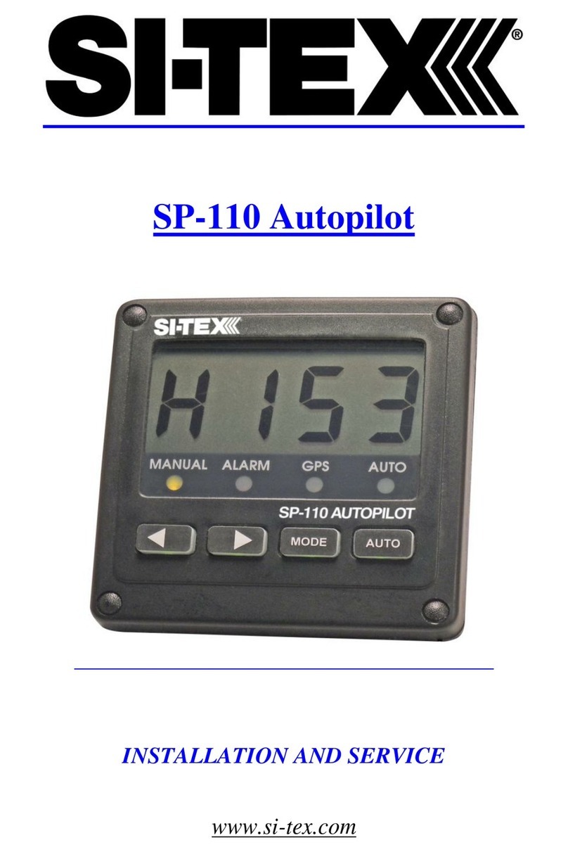
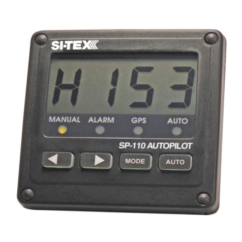
Sitex SP-110C User manual

SP-110C Autopilot
USER MANUAL
IMPORTANT: PLEASE RETAIN ONBOARD

(This page intentionally left blank)

Contents
Warning! 2
SP-110CAutopilot System 3
Initial Operational Settings (SP-110C) –
WithoutRudderFeedback 17
Turn Ratio 18
InitialOperationalSettings(SP-110CR)–
With Rudder Feedback 9
CompassAlignment 10
Rudder End Limits – Automatic Set Up
(Rudder Feedback Required) 11
Rudder End Limits – Manual Set Up
Main Screen Explained 22
Manual Steer Mode 22
Auto Steer Mode 23
GPS Steer Mode 24
Error Messages 25
(RudderFeedback Required) 12
Rudder Ratio(Proportional Gain) 13
Rudder Sensitivity(RudderTolerance) 13
Error Gain(IntegralControl Gain) 13
Rate of Change
(DerivativeGainMultiplier) 14
Rate of Turn (MaxTurnAngle) 14
Dead Band 15
BOD Correction(GPS Mode) 15
Reverse Delay 15
Advanced Option s
(Recommended forInstallers Only) 25
Steering Menu 26
Coms Menu 27
Elecom Menu(Compass Calibration) 27
GPS Menu (NMEA Corrections) 29
Factory Default 29
About 30
Setting up YourGPS Unit 30
MinimumSpeed 16
Backlight Bright 16
Wind Mode SP-110CAlarms 31
Definition of Terms 31
(Requires MWV NMEADataInput) 16
Testing Procedure 32
Trouble Shooting 33
DeclarationofConformity 34
Warranty 35
AdditionalInformation 35
Block Diagram of Full System
3
Pulse Size
18
Installation of System Components
3
Rate Tolerance
19
Display Unit
4
Period
19
Compass
5
Rate of Turn (Max Rudder Angle)
19
Rudder Feedback Unit
6
Dead Band
19
RudderFeedback/GPSWiringDiagrams
8
BOD Correction (GPS Mode)
20
GPS Wiring Connections
8
Reverse Delay
20
Hydraulic Reversing Motor Connection
9
Minimum Speed (Requires GPS SOG)
21
Mechanical Reversing Motor Connection
9
Backlight Bright
21
Solenoid Connection
9
Wind Mode
(Requires MWV NMEAData Input) 21

Warning!
• THE AUTOPILOT IS A
NAVIGATIONAL AID; AN
ADEQUATE WATCH MUST BE
MAINTAINED AT ALL TIMES
WHEN AUTOPILOT IS INUSE.
• THE AUTOPILOT MUST BE
PLACED IN MANUAL MODE
WHEN THE VESSEL IS
STATIONARY AS THE SYSTEM
WILL CONTINUE TO DRIVETHE
RUDDER TO THE END OF ITS
TRAVEL AND DAMAGE TO THE
SYSTEM MAY RESULT.
• IT IS STRONGLY
RECOMMENDED THAT THE
AUTOPILOT NOT BE USED
WHILE NAVIGATING IN
RESTRICTED WATERWAYS
AS WATER CURRENTS,
WIND CHANGES OR RADIO
TRANSMITTER INTERFERENCE
CAN ENDANGER YOUR OWN OR
OTHER VESSELS.
• IF A GPS IS CONNECTED TO
THE SYSTEM, THE AUTO MODE
WILL NOT ENGAGE BELOW A
SPEED OF ONE KNOT ANDWILL
DISENGAGE FROM AUTOWHEN
THE VESSEL SLOWS TO ONE
KNOT.
2 of 35 SI-TEX SP-110C

SP-110C Autopilot
System
The SP-110C Autopilot control
system comprises the following units:
• SP-110C display and control head.
• SI-TEX E-compass
• Rudder Feedback Unit
(SP-110CR only).
In addition the SP-110C has to be
connected to a drive unit which
controls the rudder actuator system
in order to complete the full autopilot
system. The actuator system
provides the physical movement to
the rudder responding to thedirection
of control signals provided by the SP-
110C. A rudder actuator system
comprises one of the following:
• Hydraulic system with helm pump
and ram
• Mechanical steering system
The autopilot should be connected
to a:
• Reversing motor / pump set
connected into the existing
hydraulic steering system; or
• Continuously runningHydraulic
Pump with solenoid control.
• Reversing mechanical drive unit
connected to the existing steering
mechanism
Block Diagram of full system
*Dashed line (RFU) only for
applicable for SP-110CR.
The SP-110C display provides full
control of the autopilot system and
indicates different modes for heading,
course to steer and rudder angle.
The system requires a supply voltage
of 12-24 Volts DC (Up to 29V During
Charging)
Installation of System
Components
Ensure you have all the components
of the autopilot.
Tools required:
• Screwdrivers – flat blade and
Phillips head
• Side cutting pliers
• Wire strippers
• Spanners (various) or
adjustable spanner
• 70mm hole saw
• Power drill + assortment of drill bits
• Multi meter (DVM)
• Ancillaries such as tape,
connecting block, screws, cable
ties, etc.
SI-TEX SP-110C 3 of 35

Access for wiring must be provided.
Cables have to be run to the power
switchboard, display, compass,
rudder feedback (if fitted) and
drive unit.
All wiring should be kept as far as
possible from radio aerials and aerial
cables to prevent interference to
the radio and to prevent transmitted
signals from the radio influencing
the SP-110C.
The compass must be mounted a
minimum distance of 1 metre from
any boat compass, radios, speakers
or other products with magnetic
properties to avoid interference. The
SP-110C must have a direct
connection to power supply via a 15
amp circuit breaker or a 15 amp
fused circuit and an isolating switch.
Display Unit
Position:
The SP-110C Head unit should be
mounted in a position accessible to
the steering position and protected
from direct rain or salt water.
• Select a dry position
• For in dash mounting cut a 70mm
(2.5”) hole (an optional mounting
bracket is available and may be
used for display mounting – see
your supplier)
• Drill mounting screw holes
• Mount the display using screws
supplied (304 SS – 6G)
• Fit dome plugs to cover screws
• Ensure motor (yellow) and clutch
(green) wires are not exposed
before connecting power to the
SP-110C
• Connect red wire to + 12 volts DC
(Positive)
• Connect black wire to - 12 volts DC
(Negative)
Figure 1: (below) Wiring Diagram
4 of 35 SI-TEX SP-110C

Compass
Take care when handling the
compass as it is a sensitive piece of
equipment. The compass position
is the most important item in the
installation of the autopilot. Good
course holding is dependent on the
compass being free from magnetic
interference and excessive rolling
or pitching.
Position:
• Select a dry position free from
magnetic interference. (Note other
side of bulkheads and deck heads
for magnetic type objects)
• Avoid positions near radios,
speakers, aerial cables or anyother
current carrying cable.
• Mount the compass horizontally
with the arrow (bow) pointing in the
same direction as the boat’s bow.
Use non-magnetic screws (316
grade stainless steel)
• Run cable to SP-110C display
position (keep away from other
cables)
• Connect compass cable to
SP-110C compass socket
Compass Mounting:
Vessel Bow
Figure 2: E-Compass V3
Figure 3: E-Compass V4
SI-TEX SP-110C 5 of 35

Rudder Feedback Unit
*Only for SP-110CR version.
The SP-110CR Autopilot is
supplied with an RFU (rudder
feedback unit), which provides to
the pilot a precise position of the
boat rudder.
Position:
• Refer to diagram on page7
• Mount rudder feedback adjacent to
thetiller(rudderfeedbackmovement
must copythe angular movement
ofthetiller).Usemountingbracket
if required
• Note markings on the rudder
feedback unit.P&Sindicatethe
required movement of the tiller
for course correction (Port and
Starboard).
• Rudderfeedbackismounted
with shaft uppermost
• Fitsnap lock swiveljointtorudder
feedback arm
• Fit link block to tillerarm
• Fitlinkarmfrom rudderfeedback
to tiller – adjust for correctangle
• RoutecabletoSP-110CR
display position
• Connectrudderfeedbackcable
to SP-110CR ruddersocket
• When installation is complete,
slowlymovethesteeringbyhand
to ensure:
a)
Thedirectionindicatedonthe
top of the RFU iscorrect
b)
Nounduemechanicalstrain
is placed onthefeedback or
linkage
Figure 4: Rudder feedback unit.

6 of 35 SI-TEX SP-110C

Rudder Feedback Installation
Diagram
Figure 5:
SI-TEX SP-110C 7 of 35
Note: The rudder feedback unit is
water resistant. However, if it is to
be mounted in a wet position, some
protection should be provided to
ensure the unit does not become
excessively exposed or submersed
in water.
The rudder feedback unit may be
mounted upside down, in which
case the blue and red wires in the
cable must be reversed (yellow
wire in cable is not used in the
feedback).
Note: The rudder feedback is
factory aligned. The arm should
not be removed or loosened onthe
shaft as this will affect the “O” ring
seal.

Rudder Feedback / GPS Wiring Diagrams
Pin connections from rear of plug, solder connection side.
Pin 1 has adjacent dot. See Figure 6.
Pin 1 5V Rudder Feedback Supply
Pin 2 Rudder Feedback Wiper Return
Pin 3 0V Rudder Feedback Supply
Pin 4 TX Data (heading information)
Pin 5 + GPS Input (Positive)
Pin 6 - GPS Input (Negative)
Figure 6: Pin Assignments
SP-110C View
GPS Wiring Connections
Pin connections from rear of plug, solder connection side.
Pin 5 + GPS Input (Positive) - white wire
Pin 6 - GPS Input (Return) - green wire
For GPS navigation, connect the GPS unit via the two wires coming from
the back of the rudder feedback plug on the SP-110C display unit.
Heading Data out is also available
Pin 4 + Heading Data Out (Positive) - red wire
Pin 3 - Heading Data Out (Negative) - blue wire (0 volt line)
8 of 35 SI-TEX SP-110C
Note: For information on connecting different
brands of GPS units, refer to the relevant GPS manual
Note: Pin locations are relative to pin 1 which
always has a dot adjacent.

Hydraulic Reversing Motor
Connection
• Route suitable two core cable
(10 amp min) from motor to
SP-110C display
• Connect motor cable to the yellow
and yellow/black motor wires at
SP-110C
Mechanical Reversing Motor
Connection
• Route suitable four core cable
(10 amp min) from motor to
SP-110C display
• Connect motor wires to the yellow
and yellow/black motor wires at
SP-110C
• Connect one clutch wire to green
wire at SP-110C
• Connect second clutch wire to
+ 12 VDC voltage supply
• Go to into Settings Page 2, and
choose solenoid negative for
common negative or solenoid
positive for common positive
Initial Operational
Settings (SP-110CR) –
With Rudder Feedback
The initial set up of the SP-110C
is done once the system
installation is complete and
power has been connected to
the SP-110C display control. The
set up can be done automatically
or manually Automatic installation
set up
determines the output polarity for motor
direction and rudder limit setting.
The installation procedure is
designed to work on a rudder speed
of approx. 8 to 20 seconds hard over
to hard over. The process may fail
with faster or slower rudder
movement in which case the manual
set up should be used.
The maximum rudder travel will be
set to approx. 33º each side in the
automatic set up.
Solenoid Connection
• Route suitable two core cable (5
Amp min.) from solenoids to SP-
110C
• Connect solenoid connection to
either positive or negativesupply.
• Fit diodes (eg 1N4007) to
solenoids. Ensure the line on the
diode is on the positive terminal on
solenoid.
SI-TEX SP-110C 9 of 35
Note: If a linear hydraulic drive
is used, the connections are for
mechanical drive.
Note: If the manual set procedure
is used, motor direction and both
rudder end limits must be set.
Notes:
Motor direction can be checked
with SP-110C in MANUAL by
pressing ◄ or ► once power has
been connected to the SP-110C

Compass Alignment
Your electronic compass may not be
aligned correctly due to mounting etc.
SP-110C can adjust the heading
reading from the compass to account
for alignment error.
You will require an alternative
heading reference to set the
adjustment (eg. Magnetic compass /
GPS plotter etc)
To commence:
• Switch power on to SP-110C
• Wait until Main Screen isdisplayed
(Figure 8)
• Hold MODE button, Settings Page
1 will appear (Figure 9)
• Press MODE and AUTO buttons at
the same time. Install Options 1 will
appear (Figure 10)
• Scroll down to COMPASS
ALIGNMENT using the ► Button
• Press AUTO button to edit
• The large Orange number is the
raw heading reading from the
electronic compass
• The large Green number is the
Corrected Compass (Aligned)
heading.
• Press ◄ or ► to change the
Corrected Compass heading so it
matches your alternative reference
(Figure 7)
• Press MODE to exit back to
Settings Page 1
• Press MODE to exit back to Main
Screen
• The live compass reading on the
main screen will be the Corrected
Compass heading.
• All steering will use the Corrected
Compass heading.
Figure 7: Press ◄ or ► to
change the Corrected Compass
heading so it matches your
alternative reference
10 of 35 SI-TEX SP-110C

Rudder End Limits –
Automatic Set up
(Rudder Feedback required)
To commence:
• Switch power on to SP-110C
• Wait until Main Screen is displayed
(Figure 8)
• Hold MODE button, Settings Page
1 will appear (Figure 9)
• Press MODE and AUTO buttons at
the same time. Install Options 1 will
appear (Figure 10)
• Press AUTO button to enter
Steering Menu (Settings Page 2)
Figure 11.
• Ensure USE RFU is set to YES
• Scroll down to END LIMITAUTO
using the ► Button
• Press AUTO button to start setup
(Figure 12)
• Process will take between 20 and
60 seconds to complete depending
on the speed of the motor
• If process is successful displaywill
show CAL OK SAVING….
• Press either MODE to cancel the
installation process, display will
show ABORTCALIBRATION
• If CAL ERROR is displayedan
error has occurred
• Check the drive output is
connected and rudder feedback
is moving
• Check rudder feedback installation
• To Exit menu, press MODE button
Figure 8: Example Main Screen
(Manual Steer Mode)
Figure 9: Example Settings Page 1
Figure 10: Example Install Options 1
SI-TEX SP-110C 11 of 35

Figure 11: Example Settings Page 2
Rudder End Limits –
Manual Set up
(Rudder Feedback required)
• Switch power on to SP-110C
• Wait until Main Screen is displayed
(Figure 8)
• Hold MODE button, Settings Page
1 will appear (Figure 9)
• Press MODE and AUTO buttons at
the same time. Install Options 1 will
appear (Figure 10)
• Press AUTO button to enter
Steering Menu (Settings Page 2)
Figure 11.
• Ensure USE RFU is set to YES
• Scroll down to END LIMIT PORT
using the ► Button
• Press AUTO button to enterPort
Adjustment (Figure 12)
• Press ◄ to move rudder to Port
• Press ► to move rudder to
starboard
• If direction is incorrect, reverse
the yellow wires, or change SWAP
OUTPUT in previous menu.
• Move to Port Limit, pressAUTO
button (Figure 13)
• Press AUTO again to save,or
MODE to abort.
• Scroll down to END LIMIT STBD
using the ► Button
• Press AUTO button toenter
Starboard Adjustment
• Move to Starboard Limit, press
AUTO button
• Press AUTO again to save,or
MODE to abort.
• To Exit menu, press MODE button
Figure 12: Port Limit Adjustment
Figure 13: Save Limits Confirmation
Screen
12 of 35 SI-TEX SP-110C

Rudder Ratio
(Proportional Gain)
Factory default setting is 3 and
should only be altered during
sea trials
• With Main Screen displayed
(Figure 8)
• Hold MODE button, Settings
Page 1 will appear (Figure9)
• Press AUTO to editRUDDER
RATIO
• Press ► to increase setting
(larger rudder ratio)
• Press ◄ to decrease setting
(smaller rudder ratio)
• Press MODE to return to
Settings Page 1
• Press MODE to return to
Main Screen
Rudder Sensitivity
(Rudder Tolerance)
Factory default setting is 4 and
should only be altered during
sea trials
• With Main Screen displayed
(Figure 8)
• Hold MODE button, Settings
Page 1 will appear (Figure9)
• Press ► to scroll down to
RUDDER SENSE
• Press AUTO toedit
RUDDER SENSE
• Press ► to increase setting
(more tolerance to the rudder
position error)
• Press ◄ to decrease setting
(less tolerance to the rudder
position error)
• Press MODE to return to
Settings Page 1
• Press MODE to return to
Main Screen
Error Gain
(Integral Control Gain)
Factory default setting is 5 and
should only be altered during
sea trials
• With Main Screen displayed
(Figure 8)
• Hold MODE button, Settings
Page 1 will appear (Figure9)
• Press ► to scroll down to
ERROR GAIN
• Press AUTO to edit ERRORGAIN
SI-TEX SP-110C 13 of 35
Note: Increasing the Rudder
Sensitivity too high can cause
vessel wandering
Note: A value of 1 signifies the
minimum amount of applied rudder.
When the rudder setting is too
low, vessel track will be slow i.e.:
understeer due to too little rudder
applied. A value of 20 signifies
the maximum amount of applied
rudder. When the rudder setting is
too high, vessel track will be rapid
i.e.: oversteer due to too much
rudder applied.

• Press ► to increase setting
(more turn to target heading)
• Press ◄ to decrease setting
(less turn to target heading)
• Press MODE to return to
Settings Page 1
• Press MODE to return to
Main Screen
Rate of Change
(Derivative Gain Multiplier)
Factory default setting is 3 and
should only be altered during
sea trials
• With Main Screen displayed
(Figure 8)
• Hold MODE button, Settings
Page 1 will appear (Figure9)
• Press ► to scroll down to RATE
OF CHANGE
• Press AUTO to editRATE
OF CHANGE
• Press ► to increase setting (more
dampening of error)
• Press ◄ to decrease setting (less
dampening of error)
• Press MODE to return to Settings
Page 1
• Press MODE to return to Main
Screen
Rate of Turn
(Max Turn Angle)
Factory default setting is 500°M
and should only be altered during
sea trials
• With Main Screendisplayed
(Figure 8)
• Hold MODE button, Settings Page1
will appear (Figure 9)
• Press ► to scroll down toRATE
OF TURN
• Press AUTO to edit RATE OFTURN
• Press ► to increase setting(more
attack angle)
• Press ◄ to decrease setting(less
attack angle)
• Press MODE to return toSettings
Page 1
• Press MODE to return toMain
Screen
14 of 35 SI-TEX SP-110C
Note: This limits the max turn
speed of the vessel. Reduce this
to reduce the angle of attack for
getting to target heading.
Note: Increasing Rate of Change
can help dampen Error Gain. If set
too high, vessel may never make it
to target heading.
Note: Increase Error Gain to get
on track faster. If set too high, the
vessel will overshoot the target
heading.

Dead Band
Factory default setting is 1.0° and
should only be altered during
sea trials
• With Main Screen displayed
(Figure 8)
• Hold MODE button, Settings
Page 1 will appear (Figure9)
• Press ► to scroll down to DEAD
BAND
• Press AUTO to edit DEADBAND
• Press ► to increase setting
(more allowance for error)
• Press ◄ to decrease setting
(less allowance for error)
• Press MODE to return to
Settings Page 1
• Press MODE to return to
Main Screen
BOD Correction
(Applies to GPS Mode only)
Factory default setting is 15 and
should only be altered during
sea trials
• With Main Screen displayed
(Figure 8)
• Hold MODE button, Settings
Page 1 will appear (Figure9)
• Press ► to scroll down to BOD
CORRECTION
• Press AUTO to editBOD
CORRECTION
• Press ► to increase setting
(more correction)
• Press ◄ to decrease setting
(less correction)
• Press MODE to return to Settings
Page 1
• Press MODE to return to Main
Screen
Reverse Delay
Factory default setting is 15 and
should only be altered during
sea trials
• With Main Screen displayed
(Figure 8)
• Hold MODE button, Settings
Page 1 will appear (Figure8)
• Press ► to scroll down to
REVERSE DELAY
• Press AUTO to editREVERSE
DELAY
• Press ► to increase setting
(more delay)
• Press ◄ to decrease setting
(less delay)
• Press MODE to return to
Settings Page 1
• Press MODE to return to
Main Screen
SI-TEX SP-110C 15 of 35
Note: This number increases or
decreases the angle of attack from
a GPS/ PC supplied BOD (Bearing
Origin to Destination) when in GPS
mode.
Note: This delay helps reduce
shock load on the rudder drive
train, as it controls the time
between direction changes (eg.
Port to Starboard or Starboard to
Port changes)
Note: Increase this to reduce
rudder hunting.

Minimum Speed
(Requires GPS)
Only used when no rudder
feedback SOG installed
Factory default setting is 1.0km
and should only be altered during
sea trials
• With Main Screen displayed
(Figure 8)
• Hold MODE button, Settings
Page 1 will appear (Figure9)
• Press ► to scroll down to
MINIMUM SPEED
• Press AUTO to editMINIMUM
SPEED
• Press ► to increase setting (higher
minimum speed)
• Press ◄ to decrease setting (lower
minimum speed)
• Press MODE to return to Settings
Page 1
• Press MODE to return to Main
Screen
Backlight Bright
Factory default setting is 15
(Maximum Brightness)
• With Main Screen displayed
(Figure 8)
• Hold MODE button, Settings
Page 1 will appear (Figure9)
• Press ► to scroll down to
BACKLIGHT BRIGHT
• Press AUTO to editBACKLIGHT
BRIGHT
• Press ► to increase setting
(Brighter screen)
• Press ◄ to decrease setting
(Darker screen)
• Press MODE to return to
Settings Page 1
• Press MODE to return to Main
Screen
Wind Mode
(Requires MWV NMEA
data input)
Factory default setting is OFF
• With Main Screen displayed
(Figure 8)
• Hold MODE button, Settings
Page 1 will appear (Figure9)
• Press ► to scroll down to
WIND MODE
• Press AUTO to edit WINDMODE
• Press ► to enable Wind Mode
• Press ◄ to disable Wind Mode
• Press MODE to return to Settings
Page 1
• Press MODE to return to Main
Screen
16 of 35 SI-TEX SP-110C
Note: This setting is useful for
adjusting screen brightness for day
/ night or low lit areas.
Note: When Wind Mode is ON, the
SP-110C will attempt to correct for
wind effects on vessel steering.
Note: When the vessel is below
this set speed and in Auto or GPS
mode, the SP-110C will revert
back to Manual mode.

Initial Operational
Settings (SP-
110C)
– Without Rudder
Feedback
The initial set up of the SP-110C
is done once the system
installation is complete and
power has been connected to the
SP-110C display control.
Figure 14: Example Main Screen
(Manual Steer Mode)
Figure 15: Example Settings Page 1
Figure 16: Example Install Options 1
Figure 17: Example Settings Page 2
Table of contents
Other Sitex Autopilot System manuals
