SIUI CTS-7700 User manual

DCY2.782.7700SS/V5.0/B-E
Digital Ultrasound Imaging System
OPERATION MANUAL


I
Contents
Preface………………………………………………………………………………………….Ⅲ
1 Application Scope, Operation Condition, Safety and Caution.........................1-1
1.1 Application Scope.................................................................................................1-1
1.2 Operation Condition..............................................................................................1-1
1.3 Power Requirement..............................................................................................1-2
1.4 Safety....................................................................................................................1-3
1.5 Caution..................................................................................................................1-4
1.6 Classification…………………………………………………………………………….1-6
2 Composition, Principle and Specifications.......................................................2-1
2.1 Composition and Operation Principle...................................................................2-1
2.2 Technical Specifications .......................................................................................2-2
3 Introduction to Components Parts.....................................................................3-1
3.1 System Configuration............................................................................................3-1
3.2 Introduction to Component Parts..........................................................................3-4
4 Installation, Maintenance and Inspection..........................................................4-1
4.1 System Installation................................................................................................4-1
4.2 Maintenance and Inspection.................................................................................4-1
4.3 Relocation of System…………………………… …………………………………… 4-4
5 System Setup.......................................................................................................5-1
5.1 Operation Method for System Setup Menu..........................................................5-1
5.2 Setup Menu and Methods.....................................................................................5-1
6 Imaging.................................................................................................................6-1
6.1 Preparation ...........................................................................................................6-1
6.2 Selecting Probe and Exam Type..........................................................................6-1
6.3 Preliminary Imaging..............................................................................................6-6
6.4 Adjusting Image....................................................................................................6-9
6.5 Changing Image Display Range.........................................................................6-12
6.6 Image processing................................................................................................6-13
7 Annotation of Image Information .......................................................................7-1
7.1 Inputting Patient Information.................................................................................7-1
7.2 Adding Annotation on Image ................................................................................7-2
7.3 Body Mark.............................................................................................................7-8
7.4 Adding Arrow ......................................................................................................7-11
8 Measurement and Calculation............................................................................8-1
8.1 Key and Menu for Measurement & Calculation....................................................8-1

II
8.2 Display and Clear of Meas/Calc Result...............................................................8-16
8.3 Operation of Meas/Calc......................................................................................8-17
9 Cineloop, Image Storage and Print ....................................................................9-1
9.1 Cineloop................................................................................................................9-1
9.2 File Storage...........................................................................................................9-2
9.3 Temporary Image Store and Recall......................................................................9-3
9.4 Image Print............................................................................................................9-4
10 Maintenance, Troubleshooting, Transport and Storage ................................10-1
10.1 System Maintenance ........................................................................................10-1
10.2 Troubleshooting................................................................................................10-1
10.3 Contact Information...........................................................................................10-3
10.4 Transport and Storage Condition......................................................................10-3
10.5 Disposal............................................................................................................10-3
Appendix A Abbreviation............................................................................................... A-1
Appendix B Trackball Function Indication………………..…… ……….…….……... B-1
Appendix C Discription of Symbol.......................................................................... C-1
Appendix D Acoustic Output Parameter...………………..…………….…….…….... D-1
Appendix E Range,Precision and Accuracy of Ajustment/Display Parameter.…E-1
DCY2.782.7700SS/V5.0/B-E

Preface
III
Preface
To use this system correctly and safely and to ensure a long life, the user should
thoroughly understand the functions, operations, instructions as well as its maintenance.
Please read the information in this manual carefully before using the system.
This system has been designed and manufactured safely for the operators and patients.
However, for ensuring safety and reliability, please pay attention to the following
instructions:
a) This system should be operated only by or under the guidance of a qualified
person.
b) This system,belongs to Type BF Class I according to IEC 60601-1:2005. Please
operate this system by following the safety requirements described in Chapter 1.
c) Do not try to remodel the system. If necessary, contact our agent or us for help.
d) The system has been completely adjusted and fixed before delivery. Do not try to
readjust any adjustable parts that have been well fixed.
e) If any abnormality occurs during operation, turn off the power supply immediately
and contact our agent or us for help.
f) Connect the power cable of the unit to a grounded power socket at ground
impedance of 0.1Ωor less.
g) Accessory equipment connected to the analog and digital interfaces must be
certified according to the respective IEC standards (e.g. IEC 60950 for data
processing equipment and IEC 60601-1 for medical equipment). Furthermore all
configurations shall comply with the valid version of the system standard IEC
60601-1-1. Everybody who connects additional equipment to the signal input part
or signal output part configures a medical system, and is therefore responsible that
the system complies with the requirements of the valid version of the system
standard IEC 60601-1-1. If in doubt, consult the technical service department or
your local representative.
h) The system does not provide special protection functions or measures for use with
high frequency operation equipment. The users should be cautious for such
application.
i) This Operation Manual may be slightly different from that of your equipment due to
system software version, as well as configuration of options and accessories. The

Preface
IV
actual system that you purchase shall prevail.
j) The company shall be responsible for accuracy and integrity of this Operation
Manual.
k) The company reserves the final right to interpret this Operation Manual.

Application Scope, Operation Conditions, Safety and Cautions
1-1
Chapter 1
Application Scope, Operation Conditions,
Safety and Cautions
1.1Application Scope
The system is a general-purpose diagnostic ultrasound imaging system designed
exclusively for use in a wide variety of extracorporeal body imaging procedures. A
general-purpose system supports various transducers and related application software
packages allowing for the collection, display and analysis of ultrasound information.
Usages include, e.g. general-purpose imaging, cardiac, OB/GYN, breast, prostate,
vascular, intra-surgical, depending on the operating system specific software packages
and compatible ultrasound transducers (this product does not support intra-surgical and
endocavity transducers).
1.2Operation Conditions
a) The system should be operated under the following ambient conditions for the safe
and correct operation :
zAmbient Temperature: 0℃~40℃;
zRelative Humidity: 30% To 85%;
zAtmospheric Pressure: 700hpa To 1060hpa.
【Note】:If the operation is beyond the ranges above, no normal ultrasound images
are ensured. If the system is stored for a long time, the ventilation of the stored
place shall be considered.
b) Strong sources of radiated emissions or electromagnetic waves, from broadcast &TV
station for instance, may cause the system to display with noise. Keep this system

Application Scope, Operation Conditions, Safety and Cautions
1-2
away from these kind of radiated emissions or electromagnetic waves.
c) Do not operate this system while other devices are operating with motor or silex
switch in the same power phase; otherwise, noise will disturb your system through
the power cable.
1.3 Power Requirements
Never use this system when the power supply does not meet the following requirements,
otherwise, the system may possibly be damaged.
a) Power Voltage: Single phase, 100-240V~, tolerance±10%; 50Hz/60Hz±1Hz, (230V ±
23V~ for EU countries), 50Hz±1Hz;
b) Connection of grounded device: use a grounded socket. Before connecting to the
power supply, connect the additional potential equalization conductor to the
equipotential terminal on another grounded system or an external grounded device;
c) The removable multi-jack socket provided together with the system can only be used
to supply power for the system equipment. The connection of electric devices that are
not part of the system and the removable multi-jack socket may result in danger.
d) If the non-medical electrical equipment, supplied as a part of the system, is intended to
be supplied via a multiple portable socket-outlet with a separating transformer, the
direct connection of the non-medical electrical equipment to the wall outlet may result
in risks;
e) Do not try to deviate any additional multi-jack socket or wire from the removable
multi-jack socket of system devices or from the system devices;
f) Any accessories or equipment which are not listed in this manual should not be
connected to this system, otherwise, it may result in danger;
g) When the system configured as per this manual is in use, all power supply plugs of the
devices shall be connected to the same special removable multi-jack socket if the
removable multi-jack socket is powered by a special power supply device, this power
supply device shall be in compliance with requirements of EC60601-1 and

Application Scope, Operation Conditions, Safety and Cautions
1-3
IEC60601-1-1; the removable multi-jack socket for the system shall comply with
requirements of IEC60601-1-1 Appendix EEE;
h) Do not place the removable multi-jack socket on the ground, otherwise, it may result in
danger.
i) The maximum load capacity of the removable multi-jack socket shall not be less than
the total load of all the devices consisting of the system, or it may result in danger.
【Tip】: In regions where mains supply is not stable, it is recommended to use
power supply from a stabilizer with output power of 250VA, so as to avoid
damage to the system due to mains fluctuation.
1.4 Safety
The system is designed and manufactured in compliance with the international standard
IEC 60601-1:2005 To operate it safely and correctly, please follow the instructions below:
a) This system is not explosion-proof. Do not operate it in a flammable or easy
explosive environment(e.g. in the presence of anesthetics, oxygen or hydrogen);
b) The system is not waterproof. Never allow water or other liquid to drip on to the
system;
c) The system needs a protective grounding device. Its power cable should be
connected to a grounding socket. If the system is powered by a power supply
without grounding, its equipotential terminal must be connected to the
equipotential terminal on another grounded system or an additional grounded
device. Do not use the system where there is no ground terminal is available;
d) Biological safety: the same as other diagnostic ultrasound products, the material
used for this products is proved to be innocuous through a long-period trial. It will
not result in allergy or stimulation to human body and skin;
e) Ultrasound safety: ALARA(As low as reasonably achievable)should be observed.
Patients should always be exposed to the lowest practical transmit power levels
for the shortest possible time. Freeze the system and keep the probe away from
the patient if no scanning is done. Do not examine the patient with the probe on a

Application Scope, Operation Conditions, Safety and Cautions
1-4
fixed position of the body for a long time; please check the display of acoustic
output and MI, when powering on the system, input new patient ID or shift from
non-fetal to fetal application.
1.5Cautions
a) While operating the system, please follow the methods and procedures
described in this manual.
b) Always turn off the system and protect it with a dust-proof cover whenever the
system is not in use.
c) The system should be operated in a clean environment. Avoid operating it in a
place with direct sunshine, impetuous temperature change, full of dust, close to
heat source or high humidity; do not put anything on top of the main unit.
d) Avoid severe vibration; otherwise the components in the system might be
damaged.
e) Before connecting or disconnecting probe(s), firstly ensure that the main unit is
set in frozen state. It would be better to turn off the main unit power supply.
f) Freeze the image whenever no exam is performed.
g) All endocavity probes, when in use, should be covered with probe cover
compliant to ISO4074:2002. Biological warning for probe cover: If the covers
used for endocavity probes are condoms, they should be nonlubricant and
nonmedicated. Practitioners should be aware that condoms have been shown to
be less prone to leakage than commercial probe covers, have a six-fold
enhanced AQL (acceptable quality level) when compared with standard
examination gloves. Their AQL equals to that of surgical gloves. Users should be
aware of latex-sensitivity issues and have available nonlatex-containing covers.
h) The transducer assembly specific to endo-cavity use shall be not excited when it
is out of the patient’s body. Otherwise, such excitation does not comply with

Application Scope, Operation Conditions, Safety and Cautions
1-5
EMC requirements, which might result in harmful interference to other device(s)
in the environment
i) For instructions on probe disinfection and protection, follow the description in
4.2.9.
j) It is prohibited to scan eyes with the probe. Keep the acoustic power as low as
reasonably achievable (ALARA). Scan the body only in a period required for
making the diagnosis, rather than scan the body for a long time. An extended
scan might result in harm to personal health. Provided that clinical indications are
required, the system operator shall be fully acquainted with acoustic output or be
accessible to relevant thermal index. The probe, when exposed in the air and
noticeable heat from the probe itself, should not be applied to trans-vaginal exam.
Pay special attention to minimize exposed acoustic power and exposure period
when used on an embryo or a fetus.
k) To ensure safety, only qualified ultrasound coupling gel compliant to relevant
standards shall be applied.
l) During examination, in case images are interfered by an AC noise (hum-hum)
due to the patient, put a shield sheet between the body and the bed as shown in
Fig.1-1, and connect the sheet to the equipotential terminal of the main unit. The
hum-hum interference noise can be eliminated.
m) The system operator should not touch any tangible metal parts of any electronic
device in the patient environment and the patient at the same time.
n) The system does not provide special protection functions or measures for use
with high frequency surgery equipment. The user should be cautious of such
application.
o) Shut down the system in correct procedures, otherwise it might result in system
data loss or system failure.
p) Except for the USB port, do not disconnect the system or any other peripheral

Application Scope, Operation Conditions, Safety and Cautions
1-6
device (e.g. a printer) from any plug before the system is turned off, otherwise it
may result in system damage or electric shock.
q) The system is not intended for use with a defibrillator.
r) The system shall not be applied to cardiology directly.
s) Multiple devices, when interconnected, might result in accumulative leakage
current and dangers.
t) Make sure to use the special components provided by SIUI for system
component repair or replacement.
bed
p
atient shield sheet
To the equipoten-
tial terminal of
main unit
Fig.1-1 Lay a shield sheet to eliminate the hum (AC noise) interference
1.6 Classification
a) Protection against electric shock
The system belongs to general equipment, Class I Type BF applied parts.
b) Protection against ingress of water
The system belongs to Class IPX0, and the probe head belongs to Class IPX7.
Composition, Principle and Specification
2-1
Chapter 2
Composition, Principle and Specification
2.1 Composition and Operation Principle
2.1.1 System Composition
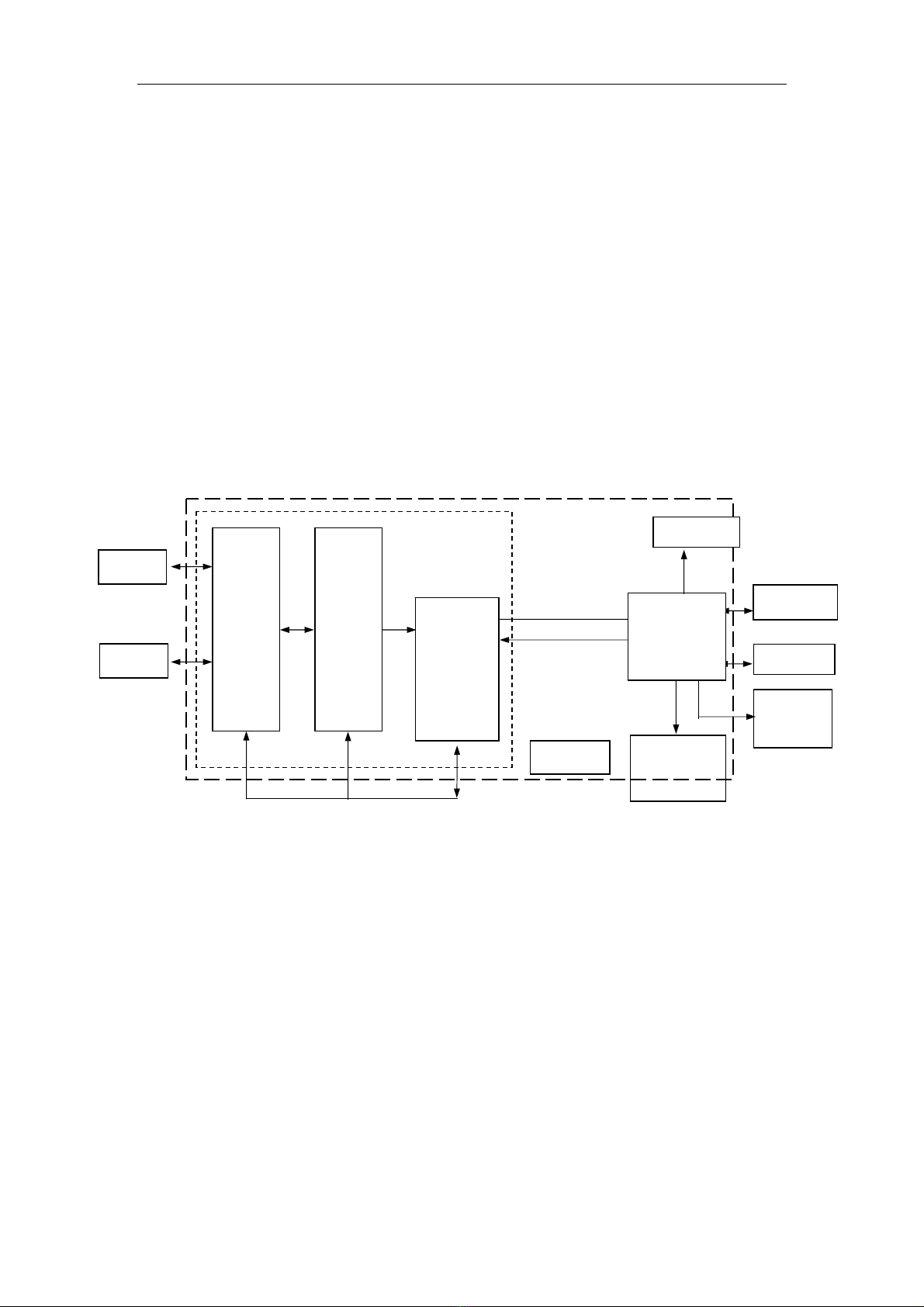
The system consists of a main unit, probes and peripheral devices. The main unit
includes Probe Connector Board, Order and Amplification Board, Digital Processing
Board, Control Platform, Operation Panel, Monitor and Power Supply. See Fig. 2-1.
Fig. 2-1 System Composition Block Diagram
2.1.2 Operation Principle
The fundamental operation principle of the main unit:
The probe connector board receives transmit excitation signals from the Digital
Processing Board and generates transmit high-voltage pulse through high-voltage drive
circuit. The high-voltage pulse then is transmitted to the working elements of the probe to
generate ultrasound. The echo of the ultrasound from human body is received by the
same working elements and converted into feeble echo electrical signals, which will be
transmitted to the Order and Amplification Board through front-end amplification. There
are two-probe connectors available on the Probe Connector Board, to which two probes
Probe1
Probe
Con-
nector
Board
Digital
Processing
Board
USB Port
Video
Out
Operation
Panel
Ultrasound
Receive/Trans
mit Front-end
Ima
g
e Data
Control
Main Unit
Power
Probe2
Monito
r
Control
Platform Network Port
Order
and
Amplifi-
cation
Board

Composition, Principle and Specification
2-2
can be connected at the same time.
The Data Processing Board generates transmit excitation signals of the current
transmission to the Probe Connector Board after a series of processing including beam
forming, aperture control dynamic apodization, dynamic filter, dynamic range conversion,
demodulation, frame correlation processing and scan conversion, and transmitted to the
ultrasound control platform through the Digital Processing Board.
The echo signals are firstly converted to digital signals after a series of processing
including beam forming, aperture control, dynamic apodization, dynamic filter, dynamic
range conversion, demodulation, frame correlation processing echo signals are first
converted into digital signals. The Digital Processing Board firstly converts echo signals
to digital signals via ADC, and further into digital image signals after a series of
processing including beam forming, aperture control, dynamic apodization, dynamic filter,
dynamic range conversion, demodulation, frame correlation processing and scan
conversion, and transmitted to the ultrasound control platform through the Digital
Processing Board.
The Digital Processing Board on one hand transmits digital image signals to the control
platform, on the other hand receives control information from the control platform and
generates corresponding control data to achieve control of the front end.
The control platform is the managerial center of the whole system, which receives
operation command from the operation panel, and control the whole system based on
the current state of the system. The other functions that the control platform fulfills also
include measurement and calculation, interface display and video processing,
management of patient data and image, as well as control of storage, printing and
communication.
2.2 Technical Specifications
2.2.1 Scanning Mode: Convex and linear array scanning.
2.2.2 Display Mode: B,2B,4B,M,B/M,ZOOM B
2.2.3 Probe (Basic Configuration)

Composition, Principle and Specification
2-3
Super broadband high-density multi-frequency convex probe
2.2.4 Focusing Method:
a)Transmitting focusing method: 1 ~ 4 transmitting focus(es) for selection
transmitting focus(es) for selection, 16 focusing positions for selection
b)Receiving focusing method: continuous dynamic focusing
2.2.5 Gray Scale:256
2.2.6 Beam Forming Method:
Digital beam forming, continuous dynamic focusing, dynamic aperture, dynamic
apodization
2.2.7 Display depth: Max 25.2cm
2.2.8 Probe technology:
a) Broadband probe
a) Frequency range: 2.5MHz ~9.0MHz (which can be extended to 2.0MHz~12MHz)
2.2.9 Imaging Parameter Adjustment:
B gain, M gain, 8-step TGC (Time Gain Compensation, also called “STC”), acoustic
power, focal point number, dynamic range, Smo/Edg, image persistence (frame
correlation), line density and SRT(Speckle Reduction Technology).
2.2.10 Live Zoom: 4 magnifications with the max. of ×4.0, position selectable
2.2.11 DisplayParameterAdjustment:
Display depth, display angle (for convex probes), display width (for linear
probes), image orientation (left/right reverse and 90° rotation), image polarity
(positive / negative), mage grayscale curve
2.2.12 Full Screen Sweep Speed In M Mode (s/f): 1.25, 2.5, 5.0 and 10.0 for selection
2.2.13 Cineloop: Current stored image cineloop, and hard disk cineloop; ≥512 frames,
and the replay speed is selectable.
2.2.14 Image Storage: Hard disk, USB; Temporal image storage and recall: ≥32
frames
2.2.15 Body Mark: ≥90 types for selection, with probe marks
2.2.16 Annotation: not less than 300 system predefined annotations

Composition, Principle and Specification
2-4
2.2.17 System preset
2.2.18 Image Screen Display:
a)Display all parameters related with diagnosis: system model, hospital name,
patient name, patient ID, date, time and week, probe model exam type, and
probe orientation;
b)Display all the parameters related to imaging: acoustic output power(% or dB),
depth, frame rate, imaging angle/ width, focus mark and range, gray scale,
probe operating frequency, TGC curve, depth scale, gain, Smo/Edg, frame
correlation, grayscale curve, dynamic range, zoom rate, line density and SRT.
2.2.19 Storage and Record:
a) Hard drive, in which images can be stored in the formats of Jpg/Bmp or DICOM
file and cineloop files in the format of Cine or Avi.
b) USB connection devices (Option)
c) transmit and receive images and patient data through DICOM3.0 function
(Option)
d) Printer (Option)
2.2.20 Measurement and Calculation:
a) General measurement: B mode: Distance, area, circumference, volume, angle,
histogram; M mode: Distance, time, heart rate and slope
b) Special measurement and calculation: for abdomen, cardiology, OB/ GYN,
urology, small parts, peripheral vascular and orthopedics
2.2.21 Video Port: composite video out, PAL/ NTSC format for selection
2.2.22 Monitor: High resolution and non-interlaced monitor
2.2.23 Probe Sockets: 2 pcs
2.2.24 Power Supply:
a) Power voltage: 100V-240V~,tolerance±10%, or 230±23V~ for EU countries
b) Power frequency: 50Hz±1Hz or 60Hz±1Hz
c) Power input: 250 VA

Composition, Principle and Specification
2-5
2.2.25 Physical Dimension and Weight:
a) Physical dimension (LxWxH): 415mm×320mm×310mm
b) Weight: approx. 12kg
2.2.26 Operation: continuous operation

Introduction to Component Parts
3-1
Chapter 3
Introduction to Component Parts
3.1 System Configuration
3.1.1 Basic Configuration
a) Main unit (Monitor included): 1 set
b) Probe: super broadband high-density multi-frequency convex probe: 1 pc
3.1.2 Accessories
a) Power cable
b) Potential equalization conductor
c) Dust cover
d) Fuse
【Note】: The specific accessories are subject to the Packing List.
3.1.3 Options
3.1.3.1 Probes:
a) Linear probes
b) Convex probes
c) Micro-convex probes
3.1.3.2 Storage, Print and Record Devices:
a) USB connection devices
b) Printer
3.1.3.3 DICOM3.0 port and software
3.1.3.4 UPS (Uninterrupted Power Supply)
In some areas, there may be sudden power cut due to power supply shortage, causing
system abrupt power-off, loss of data, and thus affect system stability. To avoid such
situation, it is recommended to connect a UPS device, with its power consumption at 500
VA or above, to the system.

Introduction to Component Parts
3-2
3.1.3.5 Special system trolley
3.1.4 Connection to Peripheral Devices
a) Video printer, VCR or large-screen monitor can be connected to the main unit via a
cable with a high-frequency BNC plug;
b) USB printer can be connected to the main unit via a USB port.

Introduction to Component Parts
3-3
3.1.5 Outside Drawing of Main Unit (Fig. 3-1)
Fig. 3-1 Outside Drawing of Main Unit
Table of contents
Other SIUI All In One Printer manuals


