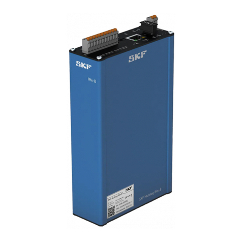
SKF Multilog On-Line System IM-P Series User manual

User manual
SKF Multilog On-Line
System IMx-P
User Manual Part No. 32146500-EN
Revision H
WARNING! Read this manual before using this product. Failure to follow the
instructions and safety precautions in this manual can result in serious injury, damage
to the product, or incorrect readings. Keep this manual in a safe location for future
reference.
Copyright 2016 by SKF Group
All rights reserved.
SKF Condition Monitoring Center – Luleå
Aurorum 30, 977 75 Luleå, Sweden
Telephone: +46 (0) 31 337 10 00, Fax: +46 (0) 920 134 40

SKF Group
® SKF is a registered trademark of the SKF Group.
All other trademarks are the property of their respective owners.
© SKF 2016
The contents of this publication are the copyright of the publisher and may not be reproduced (even
extracts) unless prior written permission is granted. Every care has been taken to ensure the accuracy of
the information contained in this publication but no liability can be accepted for any loss or damage whether
direct, indirect or consequential arising out of the use of the information contained herein. SKF reserves the
right to alter any part of this publication without prior notice.
Patents: US 4,768,380 • US 5,633,811 • US 5,679,900 • US 5,845,230 • US 5,852,351 •
US 5,854,553 • US 5,854,994 • US 5,870,699 • US 5,907,491 • US 5,992,237 • US 6,006,164 •
US 6,124,692 • US 6,138,078 • US 6,199,422 • US 6,202,491 • US 6,275,781 • US 6,301,514 •
US 6,437,692 • US 6,489,884 • US 6,513,386 • US 6,633,822 • US 6,789,025 • US 6,792,360 •
US 7,103,511 • US 7,697,492 • WO/2003/048714
Product Support – Contact Information
Product Support – To request a Return Authorization, Product Calibration or a Product Support Plan, use
the web page links for direct contact and support.
Product Sales - For information on purchasing condition monitoring products, services or customer
support, contact your local SKF sales office.
General Product Information
For general product information (i.e., product data sheet, accessories catalog, etc.), visit the Condition
Monitoring Products page on SKF.com and select the appropriate product link.
Technical Support Group
Discuss/review issues of specific interest with maintenance and reliability specialists from around the world
at the SKF Knowledge Centre.
For technical support, contact TSG-EMEA@skf.com for customers in Europe, MiddleEast and Africa.
Telephone +46 (0) 31 337 65 00
or TSG-Americas@skf.com for customers in North America, South America and Asia.
Telephone +1 800 523 7514
Telephone in Latin America +55 11 4448 8620
Product Registration
Please take a moment to register your product at www.skf.com/cm/register to receive exclusive benefits
offered only to our registered customers, including receiving technical support, tracking your proof of
ownership, and staying informed about upgrades and special offers. (Please visit our website for more
details on these benefits.)
Tell us how we’re doing!
It’s important that you’re satisfied with the quality of our product user manuals. We appreciate your
feedback; if you have comments or suggestions for improvement, please tell us how we’re doing!
031516jg

Table of Contents
Introduction 1
System Overview........................................................ 1-1
IMx-P Unit ................................................................... 1-2
LED Indicators............................................................. 1-4
Installation 2
Sensor Cables ............................................................. 2-1
Power Supply.............................................................. 2-1
Power Connector........................................................ 2-1
Cable Shielding ........................................................... 2-1
Communication Cable ............................................... 2-2
Data Communication................................................. 2-2
Ethernet Cable............................................................ 2-2
Unit Configuration 3
Analogue Inputs.......................................................... 3-1
Digital Inputs ............................................................... 3-1
Network Configuration.............................................. 3-1
IMx-P Time ................................................................. 3-3
Key Features 4
Export ODS Data ........................................................ 4-1
Diagnostic Expert System......................................... 4-2
Transients.................................................................... 4-2
Graphic Displays ......................................................... 4-4
Measurement Points ................................................. 4-5
Active Range ............................................................... 4-7
Simultaneous Processing ......................................... 4-7
Alarm Group................................................................ 4-8
Electrical Waste 5
Technical Data 6
Environmental ............................................................ 6-1
Power Supply Unit ..................................................... 6-1
Analogue Inputs.......................................................... 6-1
SKF Multilog On-Line System IMx-P TOC - 1
User Manual

Digital Inputs............................................................... 6-1
Analogue Measurement............................................ 6-2
Digital Measurement ................................................. 6-2
Signal Processing....................................................... 6-2
Interface....................................................................... 6-3
Miscellaneous.............................................................. 6-3
Quality Control............................................................ 6-3
Drawings 7
IMx-P Front Panel ..................................................... 7-1
Limited Warranty A
Index
TOC - 2 SKF Multilog On-Line System IMx-P
User Manual

1
Introduction
System Overview
IMx-P is a part of the SKF Multilog On-line System product range. IMx-P is a powerful,
versatile device designed to meet the needs of vibration analysts, service providers, and
condition monitoring professionals.
In conjunction with SKF @ptitude Observer or Analyst software, the IMx-P provides a
complete portable solution for temporary installations and troubleshooting activities.
The IMx-P system helps provide early fault detection and prevention, automatic advice
for correcting existing or impending conditions and advanced condition-based
maintenance to improve machine reliability, availability and performance.
Figure 1 - 1.
System Overview with @ptitude Observer/Analyst.
The picture above illustrates how IMx-P units are linked together in a network that is
connected via a LAN to a @ptitude Observer Monitor or Analyst IMx Service. The
@ptitude Observer Monitor or Analyst IMx Service in turn can be connected to e.g. a
LAN network making it possible for several of @ptitude Observer or Analyst clients to
link to this network.
Figure 1 - 2.
IMx-P Connected to a Laptop.
However, most likely scenario of IMx-P setup would be to connect an IMx-P unit directly
to a laptop and use SKF Multilog On-line System temporarily, taking advantage of the
portability.
@ptitude Observer or Analyst clients can also be installed on the same computer as the
@ptitude Observer Monitor or Analyst IMx Service software. Through a general
interface, also known as ODBC (open database connectivity), it is possible to link
@ptitude Observer Monitor or Analyst IMx Service login computer to an existing
database for an existing control or processing system, if desired. The @ptitude Observer
SKF Multilog On-Line System IMx-P 1 - 1
User Manual

Introduction
IMx-P Unit
Monitor or Analyst IMx Service, @ptitude Observer or Analyst clients and the database
can be separated from each other as long as they are on the same network where
ODBC calls can travel freely.
It is also possible to connect different types of on-line units in the same network, for
example, IMx-P together with IMx-S and/or MasCon systems.
IMx-P Unit
Figure 1 - 3.
SKF Multilog On-line System IMx-P.
Portable and Battery Powered
The SKF Multilog On-line System IMx-P unit is portable and battery powered.
•The built-in battery with four hours of operation time makes it possible to use in
places with no available main voltage.
•It is possible to use the on-line system temporarily in order to perform
troubleshooting for intermittent faults, installation checkouts for conformity to
purchasing agreements, startups and etc.
•The battery has a capacity of 8,5 Ah, 12 V. The charging time of an empty battery is
about 16 hours (longer charging time is allowed but not recommended).
Analogue Channels
Each IMx-P unit has 16 analogue channels (dynamic and DC).
•The analogue signal inputs are configurable for a wide variety of sensors.
•Any signals such as acceleration, velocity, temperature, and displacement or other
parameters are easily adopted.
•Each input can be configured for standard accelerometers, accelerometer sensor
power on/off by software, and process inputs (±25 V DC).
1 - 2 SKF Multilog On-Line System IMx-P
User Manual

Introduction
IMx-P Unit
Digital Channels
Each IMx-P unit has 8 digital channels.
•The digital channels may be used for measuring speed, trigger or digital status
indicating when a measurement can take place.
•Digital sensor power is software controlled.
Measurement Points
Each IMx-P unit is capable of configuring measurement points.
•Several measurement points may be configured per channel.
•In addition, Bias Output Voltage (BOV) can be measured and recorded for checking
sensor/cable faults for standard accelerometers.
•Individual conditions for warning and alarm may be set for each measurement
point.
•Warning and alarm levels may be controlled by machine speed or load.
Auto-diagnosis System
Each IMx-P unit contains an uniquely built-in hardware auto-diagnosis system.
•The unit's unique built-in hardware auto-diagnosis system continuously checks all
sensors, cabling and electronics for any faults, signal interruption, short circuits, or
power failure.
•Any malfunction triggers an alarm.
•If the main voltage fails or for some reason is disconnected, the battery power
automatically takes over.
Storage Capacity
Each IMx-P unit has 8 MB flash memory used for the following:
•2 MB for firmware, configuration files, etc.
•2 MB for trend value buffer
–About 13 000 vibration trend values can be buffered
–Speed and process data use half the space of vibration
•4 MB for spectra and time signal buffer
–About 250 spectra using 1 600 lines with phase and time signal can be
buffered
–If you use more lines, the number of spectrum is reduced.
–If you use less lines, the number of spectrum is increased
•When a buffer gets full, the oldest data is thrown away.
SKF Multilog On-Line System IMx-P 1 - 3
User Manual

Introduction
LED Indicators
Initiating IMx-P
Initiating the IMx-P is simple to carry out.
•This is done through an initiating program through @ptitude On-line Device
Configurator or Multilog IMx Configurator tool and a (portable) computer using
RS232 serial interface.
•The Network Configuration parameters, such as IP address, IMx identification
number, etc. are stored in a separate configuration file first, then transferred to the
IMx-P memory.
LED Indicators
IMx-P has LED indicators on the front panel.
Table 1-1: IMx-P LED indicators.
LED Indicator
Behavior
Description
Analog ICP Channel
1–16
On
ICP activated
Off
ICP not activated
Digital PWR Channel
1–8
On
Sensor power activated
Off
Sensor power not activated
Batt See below Battery level indication. See below for
details.
SYS
Red LED on
System fault
Off
System OK
PWR
Green LED on
System power on
Off
System power off
1 - 4 SKF Multilog On-Line System IMx-P
User Manual

Introduction
LED Indicators
Batt (Battery Level Indication)
Table 1-2: IMx-P battery level indication.
Battery Level Full Battery Level Battery Level Empty Battery Charging
Almost Empty (LED Flashing)
•The functionality of battery level indication is controlled by Firmware 2.0 or later
in conjunction with IMx-P upgrade.
•The IMx-P upgrade has been implemented for the Serial Number 1048 and later.
•It takes a minute in a stable condition to get the battery level indication state.
•For the older versions of IMx-P units:
–to get the battery level indication functionality, units must be upgraded
–the battery level indication of not upgraded units is not reliable
SKF Multilog On-Line System IMx-P 1 - 5
User Manual


2
Installation
The installation of an IMx-P must be carried out according to the instructions and
advice given in this manual. Any deviation from these directions can be made only after
consulting with the SKF Condition Monitoring Center Luleå. Installation errors can lead
to a situation where the system does not work as intended and machinery faults go
undetected. Therefore, contact the IMx-P application engineer at the slightest doubt
during the installation.
Note - In general, all cables must be routed as far away as possible from high
voltage cables. If this cannot be done, care should be taken to use high quality
shielded cables.
Sensor Cables
When routing a sensor cable, it is important that the cable is firmly fixed. The cable may
never be allowed to vibrate or oscillate, since this effects the capacitance of the cable,
and thereby the measurement result.
The sensor cable may not be routed or bundled together with supply cables because it
generates strong magnetic fields.
To connect IMx-P to sensors, the following type of sensor cable is recommended:
•Shielded, twisted pair 2 x 2 x 0,5 mm2(FKAR-PG 2 x 2 x 0.50mm2, DUE 4002 or
corresponding)
Power Supply
An external power adapter is used as the power supply. SKF provided power supplies
must be used with IMx-P. Power supplies differ in characteristics in ways that are not
obvious, and there are also physical differences in the DC-plug.
Power Connector
Power connector is a standard main connector.
Cable Shielding
IMx-P sensor inputs are differential type.
Note that the sensor cable screen needs an external ground connection.
SKF Multilog On-Line System IMx-P 2 - 1
User Manual

Installation
Communication Cable
Communication Cable
For lengths up to 15 metres, it is recommended to use pre-fabricated Ethernet twisted
pair cable FTP type, CAT5/6.
For longer cable lengths, it is recommended to use S-FTP (screened shielded twisted
pair) Ethernet cable CAT5/6.
Data Communication
IMx-P unit data communications are compliant with the Ethernet standard 10/100
Mbit.
IMx-P has two Ethernet ports which work like an internal switch.
Ethernet Cable
The Ethernet TP cable on the IMx-P is connected to a standard Ethernet RJ45
connector. Both Ethernet ports have auto detection of crossover or straight through
Ethernet cable connection. Basically, IMx-P has a built-in Ethernet switch.
It is possible to connect several IMx-P units in a daisy chain with up to eight units in a
single cable layout.
There are two LEDs on RJ45 connector.
•Yellow LED is the Ethernet traffic indicator which flickers whenever there is traffic
on the network.
•Green LED is the Ethernet link indicator which lights up when the system is
correctly connected to another network device.
2 - 2 SKF Multilog On-Line System IMx-P
User Manual

3
Unit Configuration
The ambient temperature can be found in the Environmental section under Technical
Data.
Analogue Inputs
The only setup for the analogue channels is ICP On or Off. ICP On is mainly used for ICP
type of accelerometers.
The following are the characteristics of IMx-P analogue inputs.
•Differential inputs
•DC-coupled analogue inputs which can measure both DC and AC signals in range of
±25 V
•ICP power On/Off by software configuration
Digital Inputs
The following are the characteristics of IMx-P digital inputs.
•Software controlled 24 V sensor power on/off for all digital channels 1 to 8 (power
on for 2-wire tacho sensor)
•Digital channels 1 to 4 have trigger level 2,5 V (power off for TTL pulse with
external power)
•Digital channels 5 to 8 have trigger level 10 V (power off for 12 to 24 V pulse with
external power)
Network Configuration
All IMx-P units must have an identity number between 1 and 255, unique to the
database to which it is connected.
It also requires network settings and the IP number and port number of the @ptitude
Observer Monitor or Analyst IMx Service to which it should be connected.
The network configuration is done through;
•For Observer clients, On-line Device Configurator in SKF @ptitdue Monitoring Suite.
For detailed information, refer to @ptitude Observer On-line Device Configurator
User Manual.
•For Analyst clients, Multilog IMx Configurator under Admin Tools in SKF @ptitude
Monitoring Suite.
SKF Multilog On-Line System IMx-P 3 - 1
User Manual

Unit Configuration
Network Configuration
There are two ways to configure the network:
•by software: is configured by the software via On-line Device Configurator or
Multilog IMx Configurator.
•by DIP Switches (Hardware): is done by configuring HEX rotary DIP switches
manually.
Configure by DIP Switches (Hardware)
If you have decided to configure the network manually by hardware, the following logic
must be fulfilled.
•The factory default configuration TCP/IP address is 10.0.0.1XY.
•The configuration of DIP switches requires you to set the first three part of the IP
address at Create IMx/MasCon16 Config screen of On-line Device Configurator or
Multilog IMx Configurator.
•However, the last part of the IP address will be controlled by the HEX rotary
switches on the IMx-P unit.
•For example, 10.0.0.1XY, where XY will be derived from HEX rotary switches.
•These last two digits will also form the unit ID.
•The Hex rotary switches for IMx-P are located on the front panel, labeled as HEX1
and HEX2. Refer to IMx-P Front Panel in Drawings chapter for the physical
locations.
•The HEX rotary switches have to be set manually with a small screwdriver.
Table 3-1: HEX rotary switch configuration.
TCP/IP address/Unit ID
HEX1 (x10)
HEX2 (x1)
Software defined
01
02
99
0
0
0
9
0
1
2
9
Factory default configuration TCP/IP address: 10.0.0.1XY
Serial Configuration Interface (RS232)
RS232 interface is used only when the required basic network configuration setup is
being done.
The RS232 connector is located on the right hand side of IMx-P front panel, labeled as
COM.
Use a serial null modem cable with a 9-pin D-SUB connector.
It is recommended to use a short length cable for RS232 interface in order to maintain
full communication speed.
3 - 2 SKF Multilog On-Line System IMx-P
User Manual

Unit Configuration
IMx-P Time
Important - RS232 connector is used only when the required basic network
configuration setup is being done. Therefore, the cable should not be connected to
RS232 connector at any other time.
Table 3-2: RS232 connector pinout.
RS232 Connector Pinout
Pin Description
1
NC (Not Connected)
2
Rx
3
Tx
4
NC (Not Connected)
5
GND
6
NC (Not Connected)
7
NC (Not Connected)
8
NC (Not Connected)
9
NC (Not Connected)
Figure 3 - 1.
Null Modem Cable Wiring.
IMx-P Time
IMx-P has a backup power capacitor which keeps the time for at least a month if IMx-P
was disconnected from a power inlet.
To correct or set IMx-P time, use one of the following methods.
•Automatic time synchronization
This method is preferable since IMx-P will continuously synchronize the time with
the computer that has @ptitude Observer Monitor or Analyst IMx Service running.
IMx-P uses a built-in function (NTP) in Windows for time synchronization.
SKF Multilog On-Line System IMx-P 3 - 3
User Manual

Unit Configuration
IMx-P Time
In order to activate time synchronization, refer to Time Synchronization chapter in
"@ptitude Observer Installation Manual".
•Manual set time
Use "Set time" function in @ptitude Observer or @ptitude Analyst application.
In @ptitude Observer, the function is found under a tab menu called "On-line", then
"MasCon/IMx units" interface.
In @ptitude Analyst, the function is found at Transfer / Online / Status.
3 - 4 SKF Multilog On-Line System IMx-P
User Manual

4
Key Features
Export ODS Data
The measurement data collected by IMx-P unit can be exported to be used for ODS
(operating deflection shapes) analysis. ODS analysis generates a 3-D model to illustrate
how the structure and machinery respond to the dynamic vibrations. Therefore, points
of excessive deflection, structural weaknesses and resonances can be identified and help
understand how the equipment behaves dynamically under working conditions.
The export of measurement data is done through @ptittude Observer, a function called
Export ODS data which can be found within Measurement Date interface.
Export ODS data exports a selected measurement incident to a universal file format
(UFF) which then can be imported into a software that can do machine movement
animation such as ME' Scope.
For more information on how to use this function, refer to @ptitude Observer User
Manual / System Operation / Measurement Date.
For more information on ODS analysis, for those with the access to SKF Media Finder,
may refer to the publications on NMO ESS.
Figure 4 - 1.
Example of an ODS Illustration.
SKF Multilog On-Line System IMx-P 4 - 1
User Manual

Key Features
Diagnostic Expert System
By using rule based trend curves based on FFT, it is possible to trend predefined
diagnostics such as unbalance, misalignment, bearing faults, cavitations, electric faults,
etc., which in turn can help you improve systems by modifying or creating new ones.
Figure 4 - 2.
Example of Diagnostic Expert System Graphic Displays.
Transients
A transient is considered as a non-stationary vibration event due to changes in loads or
process i.e. run-up or coast down events. In these cases, the spectral components are
dispersed in the spectrum making it impossible for analysis.
However, with transient groups in @ptitude Observer/Analyst, it is possible to analyze
this kind of events using an appropriate configuration depending on clients needs.
4 - 2 SKF Multilog On-Line System IMx-P
User Manual

Key Features
Transients
Figure 4 - 3.
Example of a 3D Plot Obtained During a Run-up.
Figure 4 - 4.
Example of a Topology Plot Obtained During a Run-up.
SKF Multilog On-Line System IMx-P 4 - 3
User Manual

Key Features
Graphic Displays
Graphic Displays
There are a number of graphic displays available in @ptitude Observer or Analyst to
facilitate data analysis. For more detailed information, refer to "SKF @ptitude Observer
User Manual" or "SKF @ptitude Analyst for SKF Multilog On-line Systems User Manual".
•Spectra displays vibration amplitude as a function of frequency where all defect
frequencies for the whole machine is automatically calculated and can be easily in a
plot as vertical bars.
•Time Waveform displays the vibration magnitude as a function of time. The time
waveform can be easily zoomed and scaling can be done automatically or manually.
•Phase spectrum displays the phase with respect to the frequency. Combined with
the amplitude spectrum, it is easy to get the phase lag for any peak in the vibration
spectrum.
•History is used to visualize the variation in machine condition over time in order to
identify impending machine faults.
•3D Plot displays vibration spectra or envelopes as a function of time, shaft speed,
power, temperature, torque or any other DC parameter. It is commonly used
during run-up and coast-down.
•Topology displays the frequency versus the time or speed and the amplitude color
coded. It is a useful display to study transient data like run-ups and coast-downs.
•Orbit is one of the best ways to analyze shaft movement. By combining phase and
amplitude data from two sensors and plotting them together, it is possible to
determine unbalance and alignment problems.
•Profile uses triggered acceleration time signal data to represent an unroundness of
any circular object.
•Gear Inspector helps detecting and visualizing the impact energy as a function of
shaft/gear revolutions.
•Bode Plot displays any type of data such as vibration amplitude/phase or process
data as a function of speed.
•Trend displays data as a function of speed and process data. It can also display
bias, process, phase, speed and digital data on extra axes.
•Trend List displays the raw trend data values in a tabular format.
•Multi Trend offers extended functionality to the normal trend plot as it is possible
to overlay data from different measurement points or sources.
•Diagnosis displays all the attached diagnoses which enables to follow progression
of machine faults.
•Polar displays a vibration signal at 1, 2, 3 and 4 time the shaft speed in the
complex domain.
•Shaft Centerline displays a rotor position dynamically which is useful at run-up.
•Combination Plots displays two or more types of diagrams for the same
measurement.
4 - 4 SKF Multilog On-Line System IMx-P
User Manual
Table of contents
Other SKF Industrial Electrical manuals
Popular Industrial Electrical manuals by other brands

Sonnen
Sonnen Protect 1300-AU-IN-ATS operating instructions

Murata
Murata GRM216R61E105KA12 Series Reference sheet

Murata
Murata GRM0335C1E750GA01 Series Reference sheet

Weidmüller
Weidmüller SMARTcharge WM-SC Series quick reference

Murata
Murata GRM0335C2A330JA01 Series Reference sheet

Gewiss
Gewiss MTSA Series quick start guide

Murata
Murata GQM1885C2A6R2CB01 Series Reference sheet

Wieland
Wieland gesis FLEX-FC EM Assembly instruction

Murata
Murata GRM0225C1C100JA03 Series Reference sheet

Murata
Murata GRM1885C2A240JA01 Series Reference sheet

Murata
Murata GQM22M5C2H820FB01 Series Reference sheet

Murata
Murata GQM1555C2D8R9BB01 Series Reference sheet