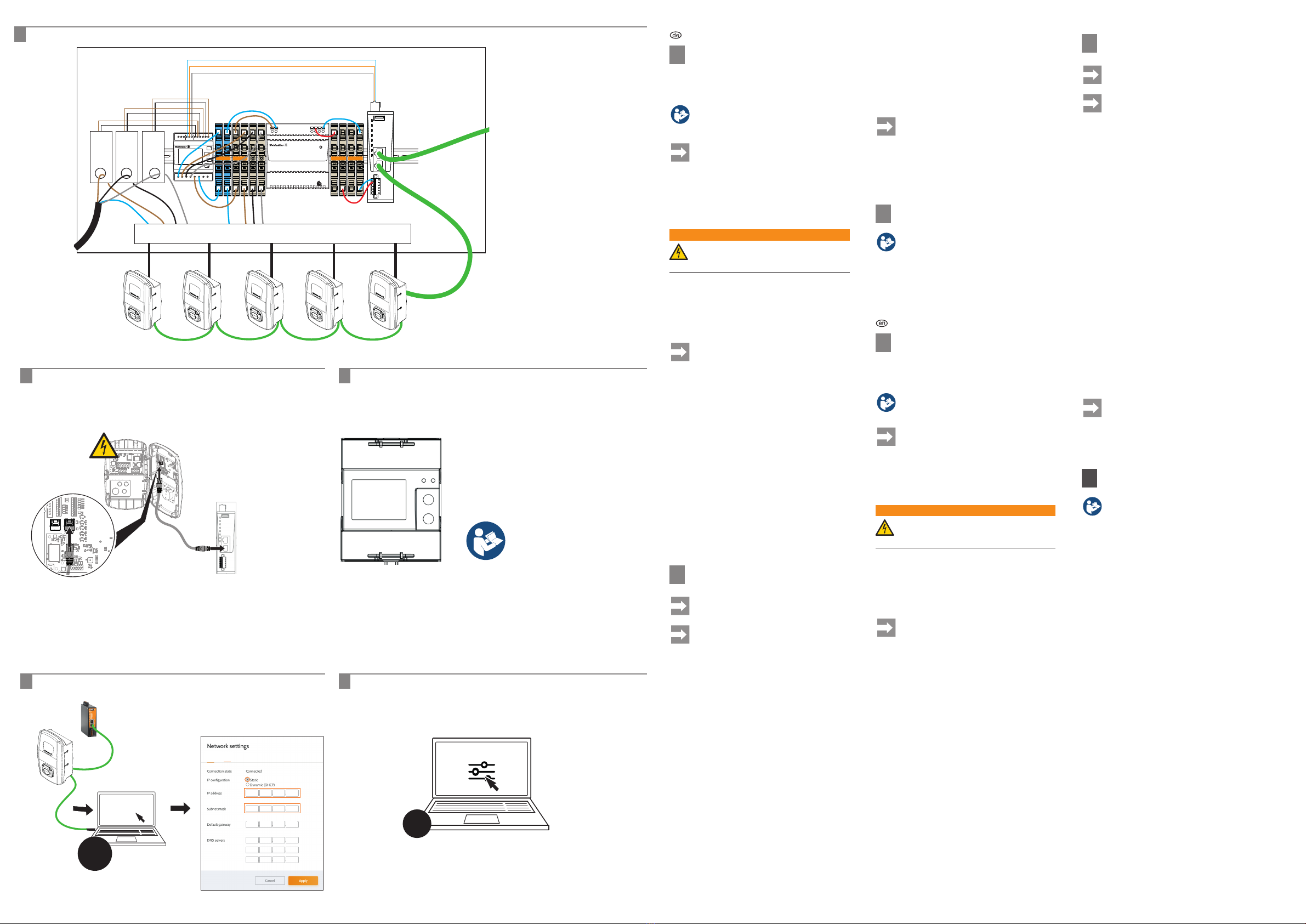
CT option
CT 1A / 5A
RS485 (Modbus) address
Only for PV plant energy meter
See installation instructions
Energiezähler kongurieren /
Conguring the energy meter
C
4
DEUTSCH
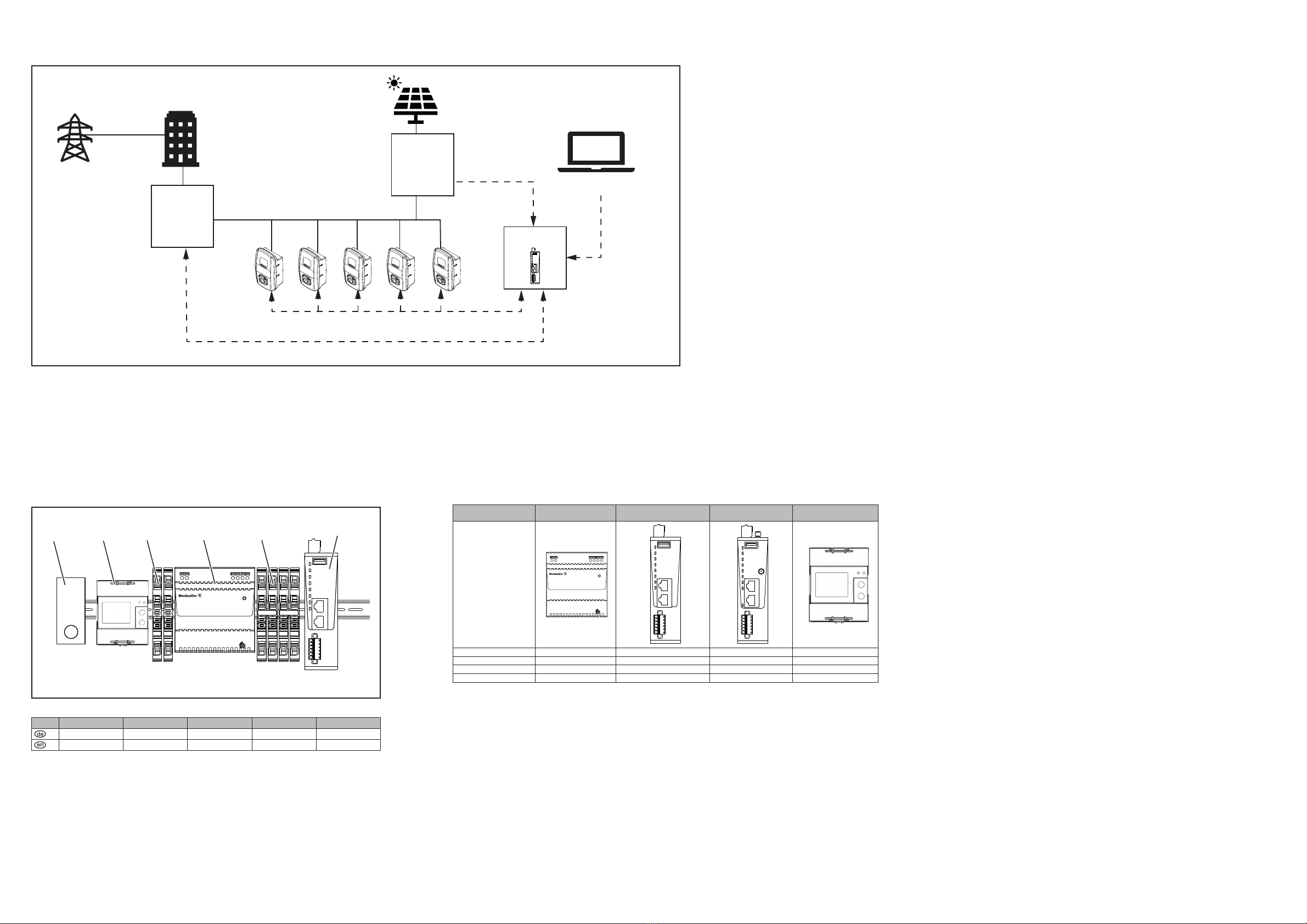
AInstallation (Beispiel 3-phasig)
Zur Installation empfehlen wir die nachfolgend beschriebene
Vorgehensweise. Je nach Auslegung der geplanten Lade-
infrastruktur ist dieser Ablauf anzupassen.
Beachten Sie die Installationsanleitungen aller
Produkte, die Sie in diesem Projekt installieren
wollen.
Folgende Produkte sind nicht im Lieferumfang
enthalten und müssen passend zu Ihrem
Projekt ausgewählt werden:
– Sicherungen
– Stromwandler (z. B. 2753030000)
– Reihenklemmen (z. B. 1992110000)
– Kabel
– Überspannungsschutz (z. B. 2591460000,
optional)
WARNUNG!
Vor Beginn der Montage- und Installationsarbei-
ten müssen die Geräte und die Zuleitungen
spannungsfrei geschaltet sein.
Geräte montieren und installieren
1. Wallboxen montieren und vernetzen.
2. SMARTcharge Komponenten und weitere Komponenten
nach Bedarf auf der Tragschiene montieren.
3. Alle Komponenten nach national und international
geltenden Standards verdrahten.
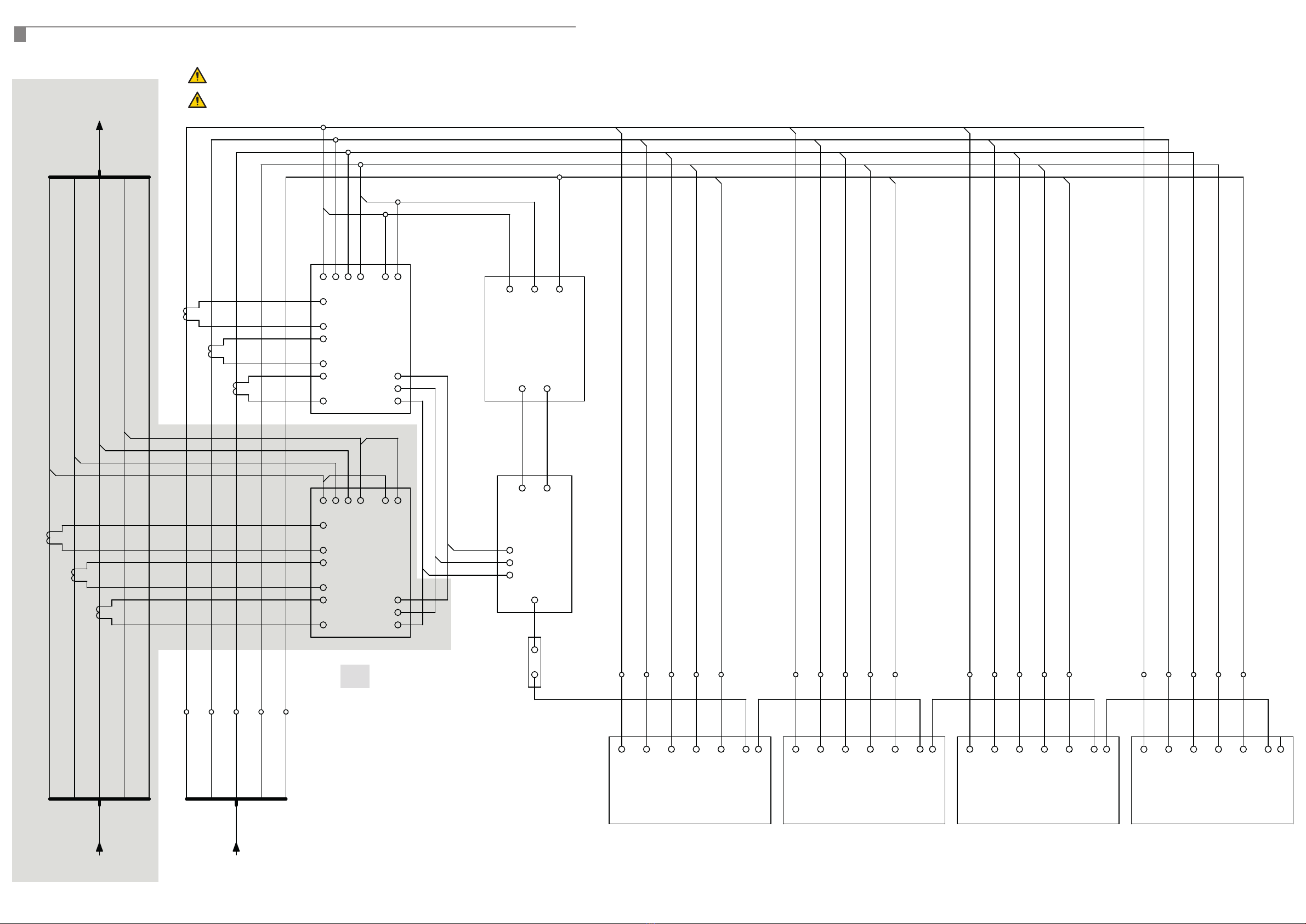
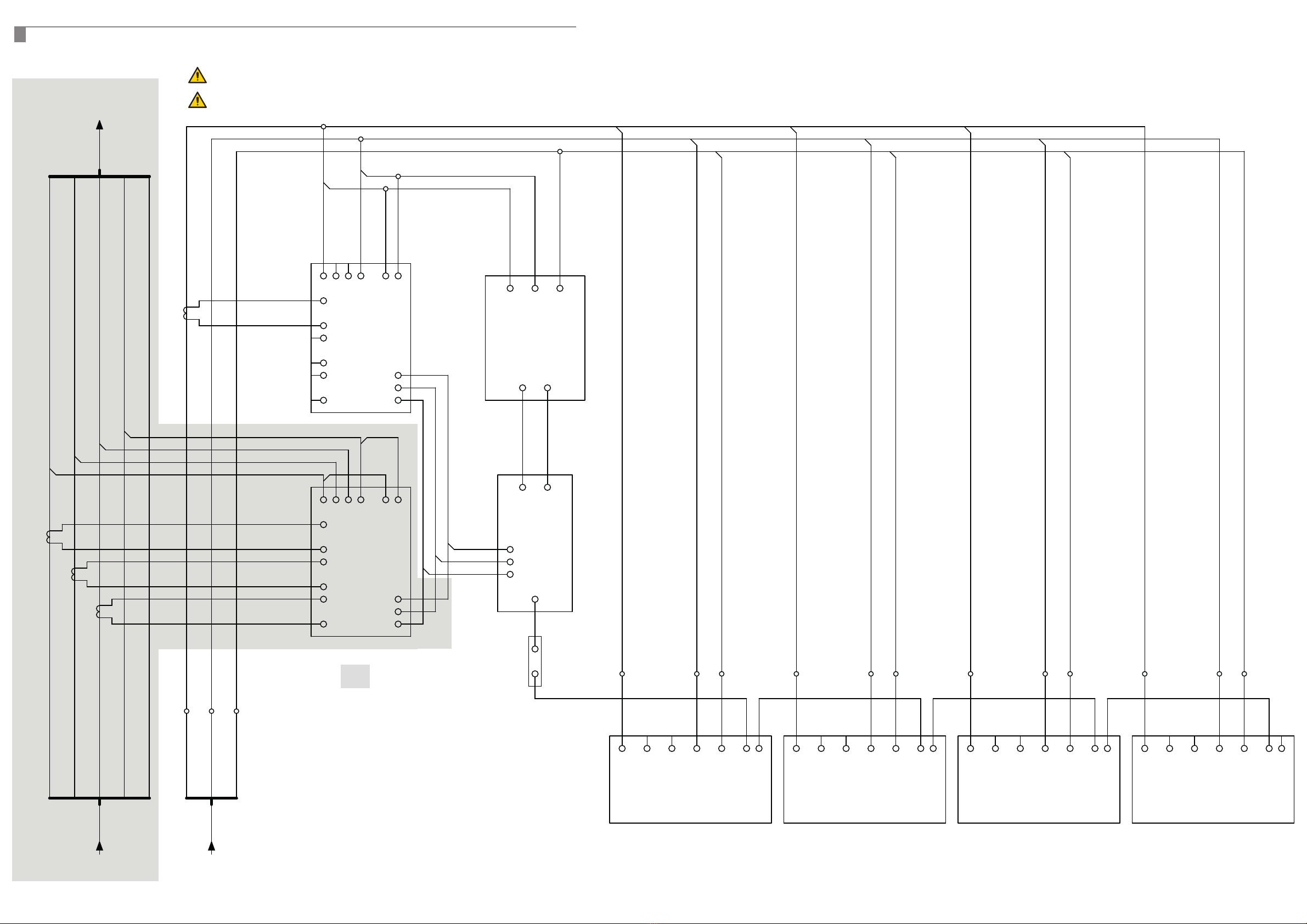
Abb. F zeigt einen Prinzipschaltplan.
Sicherungen sind nicht abgebildet und
müssen passend zu Ihrem Projekt aus-
gewählt werden.
4. Die Stromzuleitung durch den oder die Stromwandler
führen und an die vorgesehene Stromverteilung für die
Wallboxen anschließen.
5. Sicherungsgröße der Einspeisung notieren und für die
Konguration in SMARTcharge bereithalten.
6. Ethernet-Port 1 des IoT-Gateways mit einem Netzwerk-
Router oder Switch verbinden.
7. Ethernet-Port 2 des IoT-Gateways mit einer Wallbox
verbinden, siehe Abb. B.
8. Wallboxen installieren und an die Stromverteilung
anschließen.
Geräte und Software kongurieren
– Wallboxen kongurieren und in ein Netzwerk einbinden,
siehe Bedienungsanleitung
– CT Option der Energiezähler kongurieren, siehe Abb. C
– Modbus-Adresse des zusätzlichen Energiezählers
ändern (nur bei Projekt mit PV-Anlage), siehe Abb. C
– IoT-Gateway kongurieren, siehe Abschnitt D
– SMARTcharge kongurieren, siehe Abschnitt E
DIoT-Gateway kongurieren
Nach der Installation des IoT-Gateways dauert
es ca. 6 Minuten bis die Benutzeroberäche
angezeigt werden kann.
Bei Auslieferung ist der Ethernet-Port 1 als
DHCP konguriert.
u-OS starten, siehe Abb. D
►Verbinden Sie Ihren Rechner per Ethernet mit einer
Wallbox, die mit dem IoT-Gateway verbunden ist.
Ihr Rechner muss sich in demselben IP-Adressbereich
benden wie das IoT-Gateway.
►Geben Sie in der Adresszeile Ihres Broswers die IP-Ad-
resse des IoT-Gateways ein:
Ethernet 2: 192.168.1.101
► Klicken Sie auf Log in.
Sie werden aufgefordert, Ihre Anmeldedaten einzugeben.Bei
Auslieferung gelten folgende Anmeldedaten:
– Benutzername: User
– Passwort: zyVt45Nv0y
► Geben Sie den Benutzernamen und das Passwort ein und
bestätigen Sie die Eingabe.
Die Startseite von u-OS wird angezeigt.
Um den unberechtigten Zugri zu verhindern, sollten Sie
das Passwort umgehend ändern. Beachten Sie die vor Ort
geltenden Datenschutzbestimmungen.
►Ändern Sie das Passwort im Menü user/Change
password.
IP-Konguration ändern, siehe Abb. D
►Klicken Sie auf Network & internet.
►Klicken Sie auf Ethernet.
►Klicken Sie auf Edit.
►Wählen Sie eth1 (Ethernet-Port 2).
► Wählen Sie IP conguration Static.
►Geben Sie im Feld IP address eine IP-Adresse ein, die
sich in demselben Netzwerk wie die Wallboxen bendet.
Um später wieder auf das IoT-Gateway
zugreifen zu könnnen, notieren Sie sich die
geänderte IP-Adresse. Das IoT-Gateway
kann nicht auf die Werkseinstellungen und
die bei Auslieferung geltenden IP-Adressen
zurückgesetzt werden.
►Klicken Sie auf Apply.
ESMARTcharge kongurieren
Beachten Sie die integrierte Online-Hilfe.
►Um SMARTcharge aufzurufen, geben Sie in der Adress-
zeile Ihres Browser folgende Adresse:
smartcharge.weidmueller.com
►Folgen Sie den Anweisungen des Installationsassisten-
ten.
ENGLISH
AInstallation (3-phase example)
We recommend the following installation procedure. This
procedure will need to be adjusted depending on the layout
of the planned charging infrastructure.
Note the installation instructions of all products
that you want to install in this project.
The following products are not supplied and
need to be selected to match your project:
– Fuses
– Current transformer (e.g. 2753030000)
– Terminal blocks (e.g. 1992110000)
– Cables
– Surge protection (e.g. 2591460000,
optional)
WARNING!
Before starting any installation activities, the
devices and power cables must be disconnect-
ed from the mains.
Installing the devices
9. Install and connect the EV charging boxes.
10. Install SMARTcharge components and other components
on the rail as necessary.
11. Wire all components in accordance with the applicable
national and international standards.
Fig. F shows a conceptual circuit diagram.
Fuses are not shown and must be selected to
match your project.
12. Guide the power cable through the current transformer(s)
and connect it to the power distributor provided for the
EV charging boxes.
13. Note the fuse sizes at the feed-in and ensure these are
available for the conguration in SMARTcharge.
14. Connect Ethernet port 1 of the IoT gateway to a network
router or switch.
15. Connect Ethernet port 2 of the IoT gateway to an EV
charging box, see Fig. B.
16. Install the EV charging boxes and connect them to the
power distributor.
Conguring the devices and software
– Congure the EV charging boxes and incorporate them
in a network.
– Congure the CT option of the energy meter, see Fig. C
– Change the Modbus address of the additional energy
meter (only for projects with a PV installation), see Fig. C
– Congure the IoT gateway, see Section D
– Congure SMARTcharge, see Section E
DConguring the IoT gateway
After installing the IoT gateway, it takes about
6 minutes until the user interface can be
displayed.
Ethernet port 1 is congured as DHCP upon
delivery.
Starting u-OS, see Fig. D
►Connect your computer via Ethernet to an EV charging
box connected to the IoT gateway.
Your computer must be in the same IP address range as the
IoT gateway.
►Enter the IP address of the IoT gateway in the address
line of your browser:
Ethernet 2: 192.168.1.101
► Click on Log in.
You will be prompted to enter your login data. The login data
is as follows upon delivery:
– Username: User
– Password: zyVt45Nv0y
► Enter the username and password and conrm the entry.
The starting page of u-OS is displayed.
To prevent unauthorised access, you should change the
password immediately. Observe the local data security
regulations.
►Change the password in the user/Change password
menu.
Changing the IP conguration, see Fig. D
►Click on Network & internet.
►Click on Ethernet.
►Click on Edit.
►Select eth1 (Ethernet port 2).
►Select the Static IP conguration.
►In the IP address eld, enter an IP address in the same
network as the EV charging boxes.
Note the modied IP address so that you can
access the IoT gateway again later. The IoT
gateway cannot be reset to the factory settings
and the IP addresses applicable on delivery.
►Click on Apply.
EConguring SMARTcharge
Observe the integrated online help.
►To access SMARTcharge, enter the following address in
the address line of your browser:
smartcharge.weidmueller.com
►Follow the instructions provided by the installation
wizard.
Installation / Installation
A
?
SMARTcharge
u-os
Ethernet 2: 192.168.1.101
Network & internet
Ethernet / Edit
?
eth0 eth1
IoT-Gateway mit Wallbox verbinden /
Connecting IoT gateway and EV charging box
B
IoT-Gateway kongurieren / Conguring IoT gateway
DSMARTcharge kongurieren /
Conguring SMARTcharge
E
Ethernet 2
L(+)
Input
INSTAPOWER
PRO INSTA
N(-) + + - -
Output
DC OK
Adjust
Voltage inputs L N L o N o
A A
7760051004
EM120-RTU-2P
U/I
M
P
E
ESC
2
3
4
1
S1S21
S1S22
S1S23
ABG
Network/
Internet
Distribution
Feed-in
2925470000/00/03.2023