Skid Pro QA224 User manual

1
www.skidpro.com
QA224 Stump Grinder
Operation And Maintenance Manual
Skid Pro Attachments
PO Box 982
Alexandria, MN 56308
www.skidpro.com
November 2021

2 www.skidpro.com
Contents
1. IntroduCtIon And WArrAnty ................................................................... 3
1.1 Introduction......................................................................................................3
1.2 Warranty ...........................................................................................................3
2. Component IdentIfICAtIon ......................................................................... 4
3. sAfety ..................................................................................................... 5
3.1 Safety Alert Symbol And Signal Words .........................................................5
3.2 Operational Hazards........................................................................................5
3.2.1 prepAre for emergenCIes ................................................................................................ 6
3.2.2 replACe sAfety sIgns ...................................................................................................... 6
3.2.3 donot AlloW rIders ...................................................................................................... 6
3.2.4 loWer operAtIng speed ................................................................................................... 6
3.2.5 AvoId rollover................................................................................................................ 6
3.2.6 AvoId poWer lInes & underground utIlItIes .................................................................... 6
3.2.7 detACh stump grInder sAfely.......................................................................................... 7
3.2.8 trAnsport sAfely ............................................................................................................ 7
3.2.9 rAIsed AttAChment ........................................................................................................... 7
3.2.10 AvoId hIgh pressure fluIds ........................................................................................... 7
3.3 Maintenance Hazards......................................................................................7
3.4 Hazards From Modifying Equipment .............................................................8
3.5 Safety Warning Labels ....................................................................................8
4. InItIAl setup ........................................................................................... 10
4.1 Hydraulics .......................................................................................................10
5. operAtIon .............................................................................................. 10
5.1 Stabilizer Pin ..................................................................................................10
5.2 Pre-Operation Check List..............................................................................11
5.3 Attaching And Detaching..............................................................................11
5.4 Operation........................................................................................................11
6. routIne mAIntenAnCe ............................................................................ 12
6.1 Inspections......................................................................................................12
6.2 Replace Cutting Teeth .................................................................................12
6.3 Replace Flex Coupler ....................................................................................12
7. troubleshootIng ................................................................................... 14
8. pArts .................................................................................................... 15
8.1 Stump Grinder.................................................................................................15
8.2 S450 Motor ......................................................................................................16
8.3 S550 Motor ......................................................................................................17
8.4 S650 Motor ......................................................................................................18

3
www.skidpro.com
1. IntroduCtIon And WArrAnty
1.1 IntroduCtIon
Congratulations on your purchase of a Skid Pro
Skid Steer Stump Grinder. This equipment has been
designed and manufactured to meet the needs of a
discriminating buyer for efcient grinding of stumps.
Safe, efcient and trouble free operation of your stump
grinder requires that you and anyone else who will be
operating or maintaining the stump grinder, read and
understand this Operator’s Manual.
This manual covers the Skid Pro Skid Steer Stump
Grinder, model QA224.
Keep this manual with the equipment for frequent
reference and to pass on to new operators or owners.
Call your Skid Pro dealer, distributor or the factory if
you need assistance, information or additional copies
of the manuals.
OPERATOR ORIENTATION - The directions left, right,
front and rear, as mentioned throughout this manual,
are as seen from the skid steer driver’s seat and facing
in the direction of travel.
1.2 WArrAnty
Skid Pro warrants products purchased from Skid Pro
to the Original Purchaser to be free from defects in
material and workmanship for a period of twenty four
(24) months from the warranty start date.
Skid Pro’s requirement for any issue with respect to
attachments shall be limited to repairing or replacing
the defective part, as this is a parts-only warranty and
does not include any labor to replace or install the
part or downtime from resulting issue. Skid Pro has
full technical support & assistance to assure customer
replaces the part properly for optimal performance
on attachment. Skid Pro warranty service does not
include:
1. Transportation to selling dealer’s business location
or, at the option of the original retail purchaser, the
cost of a service call.
2. Used equipment.
3. Components covered by their own non-Skid Pro
warranties
4. Normal maintenance service and expendable wear
out items.
5. Repairs or adjustments caused by improper use;
failure to follow recommended maintenance
procedures; accidents or another casualty.
6. Liability for incidental or consequential damages of
any type, including but not limited to lost prots of
expenses of acquiring replacement equipment.
No agent, employee or representative of Skid Pro has
authority to bind Skid Pro to any warranty except as
specically set forth herein. Any of these limitations
excluded by local law shall be deemed deleted from
this warranty; all other terms will continue to apply.
For warranty service contact:
Skid Pro, Inc.
Toll Free: 877.378.4642
E-mail: [email protected]

4 www.skidpro.com
2. Component IdentIfICAtIon
1 - Hydraulic Motor
2 - Quick-Attach
3 - Operators Manual Holding Tube
4 - Cutting Wheel
5 - Cutting Teeth
6 - Debris Guard
1
2
3
4
5
6

5
www.skidpro.com
3. sAfety
3.1 sAfety Alert symbol And sIgnAl
Words
You must read, understand and follow the instructions
given by the operating unit manufacturers, as well as
the instructions in this manual.
The safety information in this manual is denoted by the
safety alert symbol: ^
This symbol means ATTENTION! BECOME ALERT!
YOUR SAFETY IS INVOLVED!
The level of risk is indicated by the following signal
words:
^^ DANGERDANGER
DANGER - Indicates a hazardous situation,
which, if not avoided, WILL result in death
or serious injury.
^ WARNING
WARNING - Indicates a hazardous
situation, which, if not avoided, could
result in death or serious injury.
^ CAUTION
CAUTION - Indicates a hazardous situation,
which, if not avoided, could result in minor
or moderate injury.
NOTICE
NOTICE - Indicates a situation that could
result in damage to the equipment or other
property.
3.2 operAtIonAl hAzArds
^ WARNING
Prevent serious injury or death.
Read and understand this manual before
operating stump grinder.
Always stop engine and remove key before
leaving operators seat.
Never allow anyone near the stump grinder
during operation.
Travel at a safe speed.
^ WARNING
Prevent serious injury or death from
moving parts.
Moving parts can crush and dismember.
Do not operate without guards and shields
in place.
Disconnect and lockout power source
before adjusting or performing
maintenance.
^ WARNING
Use stump grinder only for the designed
applications.
Any other use may result in personal
injury, damage to equipment and may void
the warranty.
^ WARNING
Prevent serious injury or death.
Verify stump grinder is locked to quick
attach hitch before operation or transport.
Carefully read all safety messages in this manual and
on equipment safety signs. Keep safety signs in good
condition and replace missing or damaged safety
signs.

6 www.skidpro.com
New equipment components and repair parts must
include the current safety decal.
Learn how to properly operate equipment. NEVER
operate or work around this equipment without proper
instruction, while fatigued or under the inuence of
alcohol, prescription or non-prescription medication or
if feeling ill.
Keep your equipment in proper working condition.
Knowtheregulationsandlawsthatapplytoyouandyour
industry. This manual is not to replace any regulations
or laws. Additional information may be found at:
www.asae.org or www.osha.gov.
If you do not understand any part of this manual,
contact Skid Pro at 866-232-8224.
3.2.1 prepAre for emergenCIes
Be prepared in case of emergencies.
Keep a re extinguisher and rst aid kit close to the
machine.
Keep emergency phone numbers close to your
phone.
Know your address so emergency services can locate
you if an emergency arises.
3.2.2 replACe sAfety sIgns
Replace missing or damaged safety signs.
Safety sign location are identied in Section 4.5 of this
manual.
Replacement safety signs are available from your
dealer.
3.2.3 donot AlloW rIders
NEVER lift or carry anyone on stump grinder.
NEVER use stump grinder as a work platform.
NEVER allow passengers on stump grinder.
3.2.4 loWer operAtIng speed
Keep stump grinder low and move at slow speeds on
rough or uneven terrain.
3.2.5 AvoId rollover
The equipment may rollover, resulting in death or
serious injury. To help prevent rollover:
• Travel at a slow speed.
• Avoid sharp turns & sudden movement on slopes.
• Carry stump grinder close to the ground.
• Avoid holes, ditches and other obstructions which
may cause equipment to rollover.
• Use caution when operating on slopes and do not
operate on excessively steep slopes.
• Do not exceed load capacity of equipment.
3.2.6 AvoId poWer lInes & underground utIlItIes
^^ DANGERDANGER
Prevent electrocution.
Death or serious injury can result if
equipment comes near or contacts power
lines.
Electrocution can occur without direct
contact.
Check clearance before raising equipment.
Havelocal utilities locate and markunder ground wires,
cables, pipelines and other hazards before digging.
DO NOT leave the operator’s seat if any part of the
equipment contacts electric lines or cables.

7
www.skidpro.com
3.2.7 detACh stump grInder sAfely
Detach stump grinder on a rm and level surface.
Stump grinder may fall over if detached on unlevel or
soft surface.
3.2.8 trAnsport sAfely
Carry stump grinder low.
Travel slow and avoid slopes.
3.2.9 rAIsed AttAChment
^ WARNING
Crushing hazard.
Raised, unsupported stump grinder can
fall, resulting in death or serious injury.
Never enter the area under a raised stump
grinder.
A raised stump grinder can lower unexpectedly,
resulting in death or serious injury.
NEVER enter area under a raised stump grinder.
Lower stump grinder to ground, engage parking brake,
shut off engine and remove key before servicing.
3.2.10 AvoId hIgh pressure fluIds
^ WARNING
Pressurized uids can penetrate the skin.
Hydraulic hoses can fail from age, damage
and exposure.
Use body and face protection while
searching for leaks. A tiny, almost invisible
leak can penetrate the skin, thereby
requiring immediate medical attention.
Use wood or cardboard to detect hydraulic
leaks, never use your hands.
Escaping uid under pressure can penetrate the skin
causing serious injury.
Prevent the hazard by relieving pressure before
connecting or disconnecting hydraulic lines. Verify all
connections are tight before applying pressure. Search
for leaks with a piece of cardboard or wood.
Protect hands and body from high pressure uids. If
an accident occurs, see a doctor immediately. Any uid
injected into the skin must be surgically removed within
a few hours or serious infection may result.
Doctors unfamiliar with this type of injury should
reference a knowledgeable medical source.
3.3 mAIntenAnCe hAzArds
Before servicing, park machine on a rm and level
surface, set parking brake, chock wheels, and place
a “Do Not Operate” tag on control panel. Read and
understand this manual. If you do not understand any
part of the manual, contact Skid Pro at 866-232-8224.
Always wear face and/or eye protection, safety shoes,
and other protective equipment appropriate for the job.
Always use Skid Pro replacement parts.
^ WARNING
Crushing hazard.
Before performing inspections, service or
maintenance, lockout operating unit by:
• Park machine on rm, level surface.
• Engage parking brake.
• Turn engine off and remove key.
• Place “Do Not Operate” tag on control
panel.
^ WARNING
Moving parts can crush and cut.
Keep clear of moving components.
Follow lockout procedure before
performing maintenance.

8 www.skidpro.com
^ WARNING
Entanglement hazard.
Keep clear of moving components.
Wear proper protective equipment
appropriate for the job.
^ WARNING
Burn hazard.
Hot and high pressure hydraulic oil.
Allow oil to cool before servicing.
3.4 hAzArds from modIfyIng equIpment
Do not make any alterations to your stump grinder.
Altering may cause your equipment to be unsafe and
may void the manufacturers’ warranty.
3.5 sAfety WArnIng lAbels
^ WARNING
To protect you and others against death or
serious injury, all labels shown must be on
stump grinder and must be legible.
If any of these labels are missing or
cannot be read, contact your dealer for
replacement labels.
1
2
4
3
NS
NS NS
NS - No
n-Slip Pads
Decal 1
5
3
2

9
www.skidpro.com
Decal 2
Decal 3
Decal 4
Decal 5

10 www.skidpro.com
5. operAtIon
^ Quick-Attach must always be fully engaged and
in the locked position.
^ Keep bystanders away from equipment while in
use.
^ Always wear face or eye protection, safety shoes,
and other protective equipment appropriate for
the job.
^ Do not operate, work on or around this machine
while under the inuence of alcohol, drugs or if
feeling ill.
^ Keep clear of moving machinery at all times.
^ Turn off machine before exiting operator station.
^ It is your responsibility to operate this equipment
safely. You must be familiar with the equipment
and all safety practices before use.
^ Do not allow untrained or unqualied people to
operate this equipment.
5.1 stAbIlIzer pIn
Remove stabilizer pin before use to allow cutting wheel
frame to pivot while grinding.
D005443
4. InItIAl setup
4.1 hydrAulICs
^^ WARNING
Pressurized uids can penetrate the skin.
Disconnect and lock out power source
before disconnecting and/or connecting
hydraulic hoses.
Thestumpgrinderisequippedwith short hoses that are
connected to the hydraulic motor. You must connect
your skid steer hoses to these hoses.
Skid steer hoses must be the same size as the stump
grinder hoses. Using smaller diameter hoses will
decrease hydraulic ow.
The stump grinder will have pressure and return
connections. Pressure hose on stump grinder will have
a red tie band (A) on it.
The hose end size is 1/2 in. male JIC for the pressure
and return hoses.
Connect skid steer hoses to the stump grinder hoses.
Be sure stump grinder pressure hose with red tie band
(1) is connect to skid steer pressure hose.

11
www.skidpro.com
5.2 pre-operAtIon CheCk lIst
It is operators responsibility to perform the following
checks prior to operation of equipment.
Review and understand this manual and operating unit
manual.
Verify safety decals are installed and legible. Replace
if damaged or missing.
Verify that all hardware is tight.
Inspect hoses and ttings for wear, damage and leaks.
Replace damaged or leaking hoses before use.
Verify that local utilities have marked all underground
wires, cables and pipelines.
Refertooperatingunitoperator’smanualforprestarting
instructions.
Check swing frame to verify that it is free from
obstruction and can operate smoothly without binding.
Never bar over the rotor, This could cause damage and
result in personal injury or equipment damage.
The stump grinder must be lifted in a vertical direction
only. Due to the weight of the rotor the device must be
adjusted accordingly.
5.3 AttAChIng And detAChIng
1. Read and follow all safety instructions.
2. Attach skid steer to stump grinder. See skid steer
Operator’s Manual.
3. Verify pins are secure in the correct position.
4. Connect hydraulic hoses. Verify hydraulic hoses
are clear of pinch areas.
5. Move to a clear open area to test functions.
5.4 operAtIon
Before starting, stand to side of stump grinder and
look at center point on bottom of cutting wheel, this will
appear different from the skid steer seat and can be
very deceiving.
Operate all functions in an open area with skid steer in
idle to get a good feel for the controls.
^ WARNING
Prevent serious injury or death.
Turn off engine and remove key before
leaving operator’s seat.
1. Attach stump grinder to skid steer. See Attaching
And Detaching in this section.
2. If stump is on a grade, position skid steer in low
area. This will position stump grinder in high area
for a greater advantage of weight for stable cutting.
3. Move over stump so cutting wheel torques
downward, pushing frame up to avoid binding.
4. Engage cutting wheel and slowly lower it in a
controlled manor to desired cutting depth. Always
lower cutting wheel beside stump, never try cutting
down, always cut from the side.
5. Slowly move into the stump.
6. If cutting wheel stalls, stop motion and rise slightly.
After a complete pass, move to home position and
lower cutting wheel to desired position for next
pass.
7. Continue lowering the passes until sump is
completely removed.
12 www.skidpro.com
6. routIne mAIntenAnCe
6.1 InspeCtIons
Check hydraulic hoses and ttings daily for leaks.
Replace hose if worn or damaged.
Inspect the unit for any buildup of contamination (dirt,
stones, etc.).
Check cutting teeth every 2 hours of use. Keep cutting
teethingoodcondition.Unitwillcutfasterandremaining
teeth will last longer if broken teeth are replaced.
6.2 replACe CuttIng teeth
^ WARNING
Crushing hazard.
Raised, unsupported stump grinder can
fall, resulting in death or serious injury.
Never enter the area under a raised stump
grinder.
1. Support stump grinder to prevent falling.
2. Stop skid steer engine and remove key.
^ WARNING
Moving parts can crush and cut.
Keep clear of moving components.
Lockout operating unit before performing
maintenance.
3. Inspectcuttingteethfordamage.Replaceindividual
teeth as needed.
4. Remove lock nut (1) and cutting tooth (2).
5. Install replacement tooth and lock nut. Tighten
locknut (1) to 95 lb/ft (129 Nm) of torque.
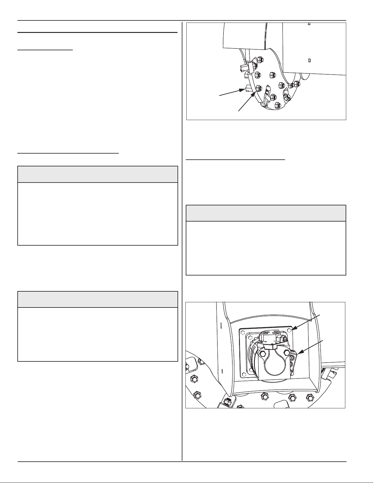
6.3 replACe flex Coupler
1. Lower stump grinder to ground.
2. Stop skid steer engine and remove key.
^ WARNING
Moving parts can crush and cut.
Keep clear of moving components.
Lockout operating unit before performing
maintenance.
3. Remove four cap screws (1) and remove hydraulic
motor assembly (2).
1
2
1
2

13
www.skidpro.com
4. Remove and replace ex coupler (3).
Note: Coupler hub on rotor shaft and motor shaft do
not have setscrews. Setscrews are not needed in this
application.
5. Install hydraulic motor assembly.
3

14 www.skidpro.com
7. troubleshootIng
Problem Probable Cause Solution
Cutting wheel does not spin. Cutting wheel jammed. Remove material from cutting
wheel.
Low oil. Check oil level in skid steer. Add if
necessary.
Not enough oil ow. Check ow control on skid steer.
See your dealer.
Cutting wheel low on power. Low oil. Check oil level in skid steer. Add if
necessary.
Oil lter plugged. Replace skid steer oil lter.
Relief valve not set properly. Set relief valve. Pressure should be
between 2,500 and 3,500 psi.
Not enough oil ow. Check ow control on skid steer.
See your dealer.

15
www.skidpro.com
8. pArts
8.1 stump grInder
ITEM NO.
PART NUMBER
DESCRIPTION
QTY.
1
D001127
Skid steer attachment
1
2
SSQT plate
Standard skid steer plate
1
3
D001028
1 x 5" Flange Pin
2
4
D001674
1/2" Hose holder
1
5
Sheet
-
6
D001428
Rotor Frame
1
7
D002336
S1028 Rotor with teeth
1
8
S1028
Rotor Assembly with Keyed Shaft (S18 & S24) less teeth
1
9
750 3P24-1
Rotor Assembly
1
10
D001084
S18 Shaft
1
11
D002924
S1000 tooth holder block (weld- in) 750 3P24-2
8
12
S1000
5/8” threaded stump grinder tooth
34
13
D001773
Tooth Nut
34
14
B2005
4 Blot 210 Flange Green Cast
2
15
F2002
2 x.625 Fine Thread
8
16
S18-10
Safety deflector plate
1
17
D001630
6-pack holder
1

16 www.skidpro.com
8.2 s450 motor
ITEM NO.
PART NUMBER
DESCRIPTION
QTY.
1
D001503
A-Motor Mount
1
2
B2000
L110 Flex
1
3
B2012
Flex Hub L110 1.25"
2
4
B2013
L110 Flex
1
5
D003999
A-Mount Chain Coupler Assembly
1
6
D003749
A-Mount Chain Coupler – Chain
1
7
D003748
Chain Link Coupler 1-1/4 x 5/16 Keyway
2
8
D004149
Complete Hydraulic Motor with Relief Block – A-Mount
1
9
D004147
Hydraulic Motor for A-Mount Options
1
10
D004148
Complete Relief Block for A-Mount Motor
1
11
D001374
Cat Motor Spacer 1.25" Shaft
1

17
www.skidpro.com
8.3 s550 motor
ITEM NO. PART NUMBER DESCRIPTION QTY.
1 D001374 Cat Motor Spacer 1.25" Shaft 1
2 D001404 B Motor Mount 1
3 D001007 Char-Lynn 24 GPM Motor 1
4 D001009 Relief and Anti-Cav Assembly Valve Block 1
5 D001982 #214 O-Ring 2
6 D001981 #116 O-Ring 2
7 D001984 Pressure Relief Valve
1
8 D001983 Anti-Cavitation Check Valve
1
9 D001009 B-Mount Valve 1
10 D001987 #114 O-Ring 2
11 B2000 L110 Flex 1
12 B2012 Flex Hub L110 1.25" 1
13 B2013 L110 Flex 1
14 D002420 Flex L150 Hytrel Insert 1
15 D002419 Flex Hub L150 - 1.25" Keyed 2
16 D004000 B-Mount Chain Coupler Assembly 1
17 D003849 CH6018 Chain for Chain Coupler 1
18 D003995 CB6018 Chain Coupler Hub 1 ¼” Bore x 5/16” 2

18 www.skidpro.com
8.4 s650 motor
ITEM NO.
PART NUMBER
DESCRIPTION
QTY.
1
D001175
Motor
1
2
D001009
Anti-Cavitation Check Valve Assembly
1
3
D001982
#214 O-Ring
2
4
D001981
#116 O-Ring
2
5
D001984
Pressure Relief Valve
1
6
D001983
Anti-Cavitation Check Valve
1
7
D001009
B-Mount Valve
1
8
D001987
#114 O-Ring
2
9
D002062
Seal for 1.5" Shaft - 6000 Series CL Motor
1
10
D001020
L225 Flex Coupler Total Assembly with 6-Spline Insert
1
11
D001018
L225H Flex Hytrel Insert
1
12
D001024
Flex Hub L225 with 1.5" Bore
1
13
D003483
L225 Jaw Coupler - S18
1
14
S18-8
C Mount
1
15
D004001
C-Mount Chain Coupler Assembly
1
16
D003995
CB6018 Chain Coupler Hub 1 ¼” Bore x 5/16”
1
17
D003848
Chain Coupler Hub for C-Mount – Motor Side 1 ½” Bore x 3/8”
1
17
D003849
CH6018 Chain for Chain Coupler
1

19
www.skidpro.com

20 www.skidpro.com
Skid Pro Attachments
PO Box 982
Alexandria, MN 56308
www.skidpro.com
November 2021
Table of contents


