Skookum SK360 User manual
Throw out your 1940’s-technology mechanical
flybar, and replace it with a Digital Flybar.
Lightening-quick 3D and solid hovering in wind, with
a less complex, lighter rotorhead that gives you
more power or longer flight times!
SK360 Digital
Flybar
User Manual and Setup Guide
©2008 Skookum Robotics, Ltd 2
Rev 1.10 SK360 User Manual & Setup Guide
Table of Contents
1 Intro ...............................................................................3
2 Package Contents ........................................................3
3 Safety.............................................................................4
4 Mounting the Gyro........................................................4
5 Helicopter Airframe Setup ...........................................5
6 How to Check Cyclic Pitch & Phasing........................7
7 Connections..................................................................9
8 Modes, Indicators, and Power-Up.............................10
9 Gyro Setup Using the USB Interface ........................11
10 After Setup: Final Check!...........................................13
11 Flight with the SK360 Gyro........................................13
12 Basic Tuning...............................................................14
13 Remote Bank Switching and Hiller Gain ..................15
14 USB Interface Software Reference............................16
15 Advanced Tuning Options.........................................19
16 Tuning Troubleshooting Guide.................................21
Appendix A: Specifications..................................................23
Appendix B: Firmware Upgrades.........................................23
Appendix C: Warranty and Technical Support...................24
©2008 Skookum Robotics, Ltd 3
1 Intro
The SK360 Digital Flybar is a high performance, compact, and lightweight pitch
and roll stabilizer for model helicopters. Its function is to replace the traditional
flybar (stabilizer bar) and its association linkages, while saving power, increasing
flight times, and reducing repair costs. Features include:
Control Options:
Control over the Bell and Hiller ratio (direct vs. stabilized control)
Control over roll and pitch rates in-software
Control feel is adjustable in software, on the gyro case, or by remote bank
switching
Optional remote gain
Swashplate Options:
Suitable for 120, 135/140, and 90 degree eCCPM, as well as mCCPM
swashplates
Mixing In-Gyro, for higher precision
Swash Ring anti-binding algorithm
Phase Trim adjustable to +-90
Servo Options:
Works with digital or analog servos
Synchronous with receiver’s PWM frames for minimal lag
Groups swash servo PWM pulses for low swash motion error
Swash servo rate-equalizing prevents uncommanded pitch during
aggressive maneuvers
2 Package Contents
Your gyro package should include:
SK360 Gyro unit
Four strips of 3M-4408tm mounting tape
USB Interface with jumper
USB Extension Cable
CD with Interface Software
Note: If your computer can’t read mini-CDs, visit our website at:
www.skookumrobotics.com/support.html
to download the latest version of the setup software (you will not need to
update the firmware).
©2008 Skookum Robotics, Ltd 4
3 Safety
An R/C Helicopter is not a toy, and can cause serious injury to people or damage to
property. Use of this gyro places a flight control computer (the gyro unit) between
the radio receiver and the servos that drive the swash plate. If the gyro unit is
mistuned or set up incorrectly, loss of control of the helicopter may result. See
Appendix C for warranty information.
Please keep bystanders clear of the flight area at all times. Be sure to test fly away
from spectators, especially when flying the helicopter after any change in the gyro’s
setup or tuning, and keep yourself at a safe distance.
4 Mounting the Gyro
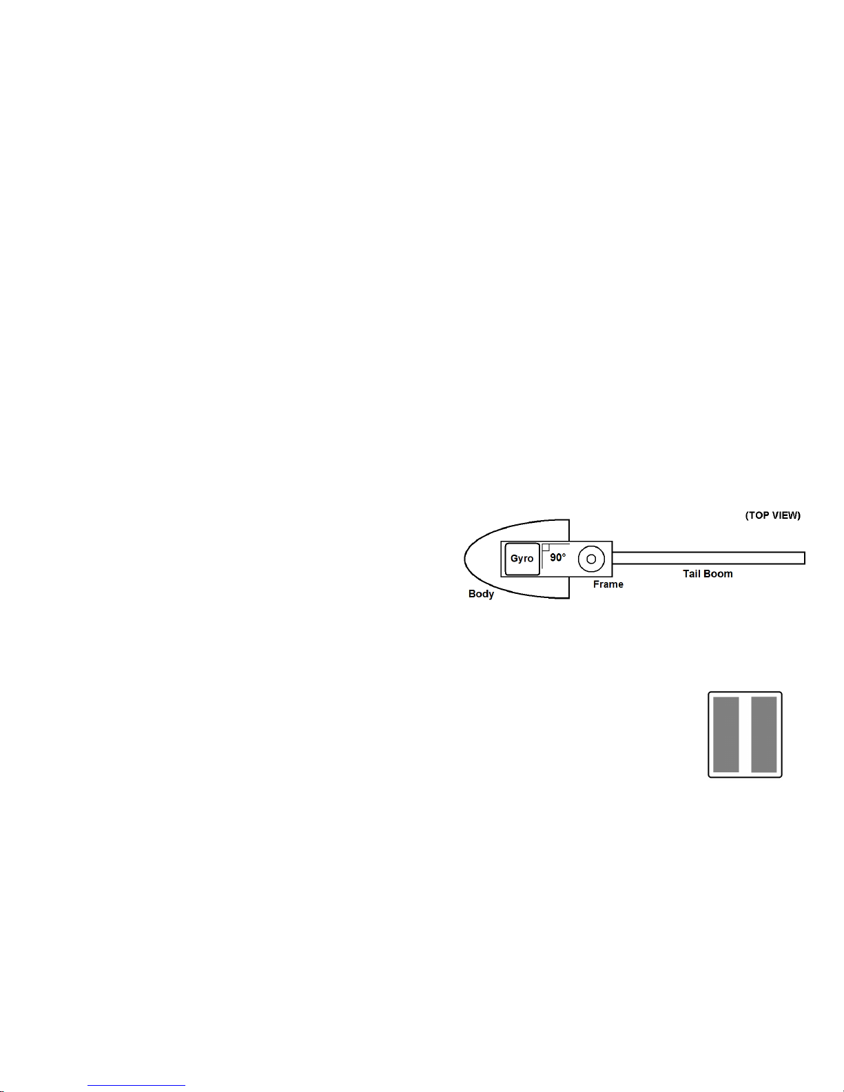
The front side of the gyro is marked on its case. The gyro unit can be mounted
upside down, backwards, or sideways, but it must be level, and have its sides
aligned as accurately as possible with the fore-aft axis of the helicopter.
Misalignments of even a few degrees (2mm or 1/16” difference between the front
and back edges of the case) may cause problems with tuning the gyro. The gyro
should also be as far as possible from any heat sources, and at least 10cm away from
Xtremelinktm receivers. The SK360 label must face up or down.
For vibration resistance, mounting tape with good damping must be used, such as
the 3M-4408tm tape included. The gyro’s case should not directly contact any hard
surfaces of the helicopter’s frame, and if a safety strap is used across the top of the
gyro, it should be padded slightly. Cables connected to the gyro should have some
slack near the gyro’s case.
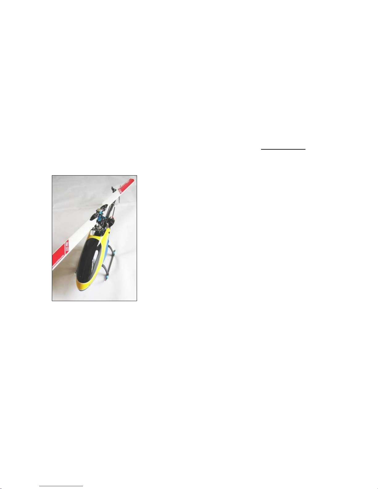
Before mounting the gyro clean its base and the
mounting site with isopropyl alcohol. Then use
two pieces of the supplied 3M mounting tape on
the base of the gyro, as shown. If you use a
pad/metal plate/pad mounting for a nitro heli, be
careful that the stack is not too thick, as this might
result in resonance.
©2008 Skookum Robotics, Ltd 5
5 Helicopter Airframe Setup
Good mechanical setup is critical to the gyro performing correctly. Please read this
section fully.
The gyro should not be used in addition to a flybar, as the results could be
unpredictable. It is intended for use where the swashplate alone drives blade pitch.
Blades:
Flat bottomed rotor blades are not recommended. They have a pitch-down moment
about their axis of rotation that could put heavy loads on the swashplate servos. The
ideal rotor blades will have a symmetrical airfoil, be torsionally stiff but a bit
flexible spanwise, and balanced both spanwise and chordwise.
Servos:
The best performance will be achieved if the swashplate servo’s full normal range of
movement is used. For good “3D” performance, you will need servos that are fast,
and if possible digital. For analog servos, check their specification, and drive them
at 6v (if they are rated for it). Stronger, faster servos will let you use higher damping
gains (see Section 15), which is important for maneuvers such as piro-flips.
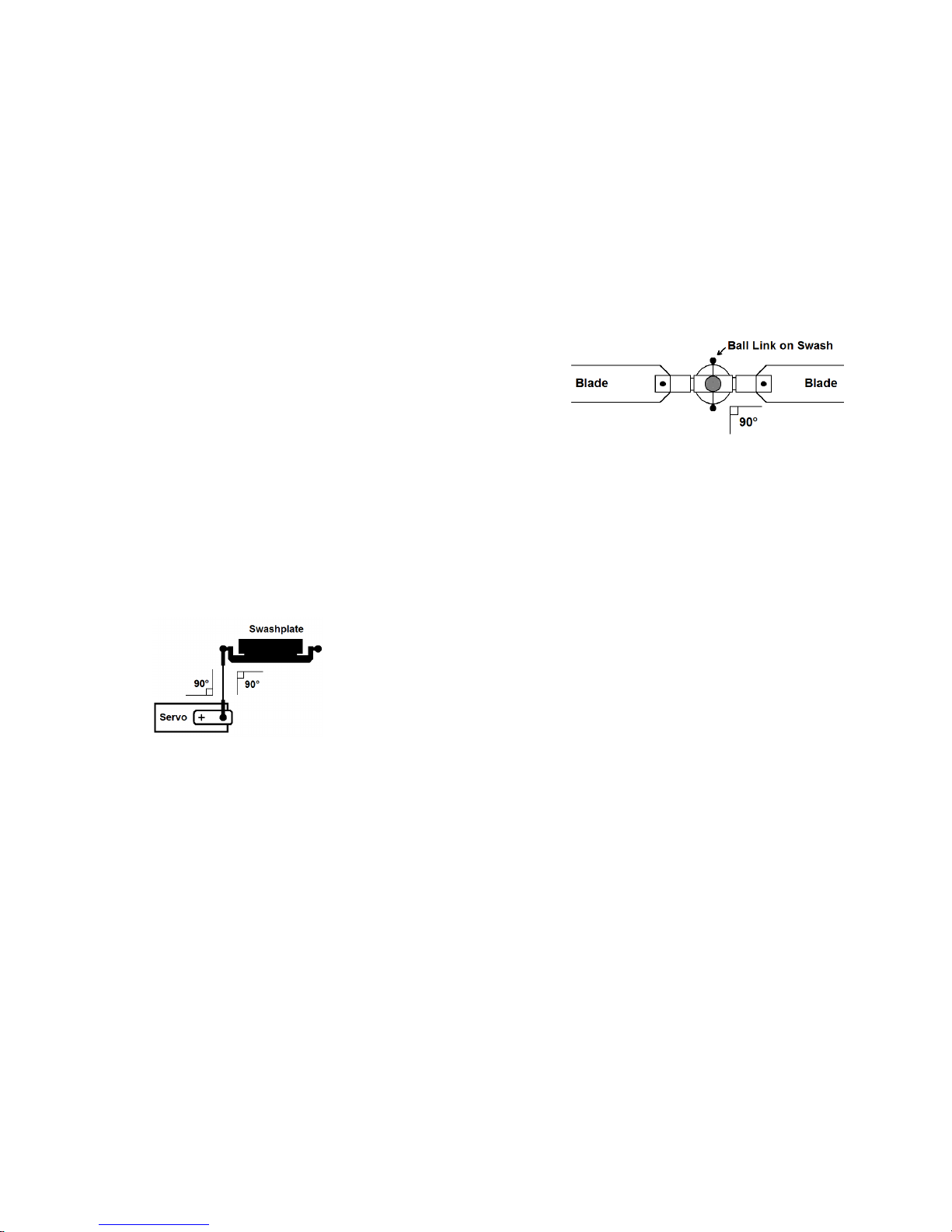
Try to have 90-degree angles between servo and blade grip arms and linkage rods,
for even movement. The gyro’s USB setup interface will allow fine-tuning of servo
centers to achieve this.
Rotorhead:
When setting up the mechanics originally designed for helis with a flybar, just
removing the flybar but keeping normal servo arm length will likely give too much
blade pitch action. Either servo travel or servo arm length will then need to be
reduced. For example, on the Aligntm TREX, you can adapt the flybar mixing arms
as travel-reduction arms on the rotorhead, to reduce the effect of swashplate slop
and reduce servo load. This will allow higher gains, and better performance.
Some kind of anti-rotation or “follower” mechanism will be needed, to keep the top
of the swashplate from rotating relative to the blade grips.
©2008 Skookum Robotics, Ltd 6
If the swashplate is not held so the linkage to the blade grips is at 90 degrees to the
blades (for 2-bladed rotors), the phase angle will need to be set to compensate. See
the diagram below.
For initial flights, the phase angle should be adjusted so that when the blades are
lined up with the heli’s tail boom, they do not move with elevator input, but do
move with aileron input (for 2-bladed rotors). This can be set either mechanically, or
through the USB setup software.
It is important that the linkages and swash have little slop and the lowest friction
possible.
How stiff the rubber rotor head dampers are will have an effect on tuning the gyro
and flight performance. Performance will be better with the teeter damping a stiffer
than normal, but too stiff can cause vibration, which is hard on the airframe, gyros,
and servos.
Tail:
Because the axis of the tail rotor disk is lined up with the elevator axis of the heli,
it’s important that you minimize tail rotor vibration. Also, if you have a belt-driven
tail, be sure that your tail boom is electrically grounded to the heli’s frame or motor
case, to prevent static electricity buildup.
Balance:
The gyro will perform best with the CG directly under the mainshaft, or very
slightly nose heavy. This is especially important for maneuvers that use fast
collective pitch changes combined with yaw, such as piros.

©2008 Skookum Robotics, Ltd 7
6 How to Check Cyclic Pitch & Phasing
The goal of mechanical and gyro swashplate setup is to get your normal collective
blade pitch range, and a cyclic range of about +-10 degrees, which means a total
range of 20 degrees. This is important. (Cyclic pitch is blade’s pitch due to aileron
or elevator input)
The rotor blades must also have the correct phasing. This means that aileron and
elevator control input change each blade’s pitch at the correct time. For most
mechanical setups, the phase angle will not need adjusting.
While checking for good cyclic throws, phasing, and even swash motion, the
gyro must be put in setup mode, by pushing the mode switch towards the gain
dials (see Section 8).
While in setup mode, all stick motions are sent directly to the swashplate as if
stability gains were all zero (the gyro only does its mixing function). The gain dials
and gain fields in the PC software will have no effect in this mode.
To check the cyclic range and phasing:
1) Set collective pitch to zero.
2) Align a blade along the fuselage, pointing over the nose of the helicopter as in
the photo below:
3) Now try full nose-up elevator control, with aileron centered. Measure the pitch
of the blade that points over the nose.
4) If the mechanical setup is ideal, the blade should not change pitch. If it does you
will need to adjust the phase angle, either mechanically at the swashplate or
using the gyro’s USB interface. If the pitch becomes negative adjust the phasing
clockwise (+), if positive then adjust it anti-clockwise (-). Note: this will give
©2008 Skookum Robotics, Ltd 8
you normal phasing (90 degree lead); multi-bladed rotors may fly better with
some positive phase trim.
5) Try full right aileron control, with elevator control centered. The blade’s pitch
should be about -10 degrees.
6) Try full left aileron control, with elevator control centered. The blade’s pitch
should be about +10 degrees.
7) Align a blade at 90 degrees to the fuselage, pointing over the right side of the
helicopter as in the photo below:
8) Try full nose-up elevator control, with aileron control centered. Measure the
pitch of the blade that points over the right side of the helicopter. It should be
about -10 degrees.
9) Try full left nose-down elevator control, with aileron control centered. The
blade’s pitch should be about +10 degrees.
If the cyclic blade pitch range is changed, the gyro’s stability gains will need to
be changed as well. For example, increasing cyclic pitch range by 10% is the same
as increasing the stability gains by 10%.

©2008 Skookum Robotics, Ltd 9
7 Connections
The gyro normally has 3 inputs, and 4 outputs, labeled on the top of its case. Note
that the USB interface does not supply power. For the inputs from the radio
receiver, the connector mapping is:
Swash Setup Type Input 1 Input 2 Input 3
120 deg eCCPM Elevator Ch Aileron Ch Pitch Ch
135/140 degree eCCPM Elevator Ch Aileron Ch Pitch Ch
“1-servo” mCCPM Elevator Ch Aileron Ch n/a
90-deg eCCPM Elevator Ch Aileron Ch Pitch Ch
Left/Right means the heli’s left and right, looking from its tail to its nose.
The SK360 needs to receive separate aileron, elevator, and pitch inputs so set the
swash-type in your radio to “1-servo” for all swash setups. You also have the
option of using the “A4” port as a remote gain and bank-switching input. But do not
connect this port to your radio until the SK360 unit is told to use it as an input with
its setup software, or your radio receiver could be damaged (see Section 13).
For the outputs to the servos, the connector mapping is:
Swash Setup Type Servo 1 Servo 2 Servo 3 Servo 4
120, 135/140 deg eCCPM Centre Right Left n/a
“1-servo” mCCPM Elev Aile n/a n/a
90-deg eCCPM Fwd Aft Right Left
©2008 Skookum Robotics, Ltd 10
8 Modes, Indicators, and Power-Up
The two primary modes are Setup mode, and Flight mode, chosen by the position of
the small switch on the gyro’s side. Towards the gain dials is Setup mode, and
away from the dials is Flight Mode.
Note: The gyro will change from Setup to Flight mode right away, but won’t change
from Flight to Setup until you also cycle its power.
Setup mode lets you use the USB connection, and also used for mechanical setup -
control motions pass straight through, with no stabilizing action. While in this mode,
the indicator LED will slowly flash green.
In Flight mode, the LED Indicator will show solid red while it’s still initializing, and
turn solid green when it’s ready to fly. The gyro will not finish initializing unless it
is completely still. It will also not read in new values from the gain dials until it is
left still for a few seconds.
The option button is used for Firmware Updates (described in Appendix B).
WARNING: Always check before flight that the LED is solid green. If you take
off in setup mode the flight will be “very exciting”, short, and possibly also
expensive.
The LED flashing red rapidly indicates an error. There are four possible causes:
1. The cyclic stick wasn’t centered at initialization in flight mode
2. The supply voltage fell below 3.6v at some point
3. It is too hot or too cold
4. The gyro has a systems fault
If the first three causes can be ruled out, please contact technical support.

©2008 Skookum Robotics, Ltd 11
9 Gyro Setup Using the USB Interface
Step 1: Connecting
First install the USB Interface software for your SK360 gyro. Unplug the
swashplate servos the gyro for now.
Set your radio’s transmitter so Aileron, Elevator, and Pitch (Collective) are
output each on a separate channel (“Normal” or “1 Servo” swashplate
mode).
The initial setup will be easier if you use a straight-line pitch curve, and no
expo or dual rates. Later those features can be set in the transmitter as you
normally would.
Connect the gyro to the USB interface, and set the mode switch on the
gyro toward the gain dials to put it in setup mode. Turn on the heli’s
power, and start the setup software.
Check that the connection indicator in the upper left is green and says
Connected.
Step 2: Match the Gyro to Your Transmitter
In the Offline Setup Values area in the lower half of the window, click the
Swashplate tab. Then select the Swash Type that matches your heli’s
swashplate, and make sure Mixing Location is set to In Gyro.
Now click the Control tab. Center all the trims on your transmitter, and be
sure the cyclic stick is centered.
Click the Send Setup button, or press the F1 key to set the changes on the
gyro. You must SEND the setup whenever you want to test changes.
After a few seconds, check Inputs from Receiver again. The % values for
Elevator, Aileron, and Pitch should be close to zero. You can trim the
collective pitch centering on the Controls tab.
Try moving the elevator stick towards you (nose up), and look at the Pilot
Control field under Elevator. The number displayed should be close to
100% and show green. If it is negative, reverse that channel in your radio.
If it’s too low or reaches 100% much before the stick’s limit, adjust
endpoints and sub-trims for that channel in your radio.
Repeat for Aileron Pilot Control, but move the stick right (green). Then
repeat for the Pitch input, but move the stick up (green).
Step 3: Check the Gyro’s Sense Directions
Now look at the Gyro Rates fields in the Live Data area. Note: the Rate
fields only sense movement, not angle.
Pick up the heli and slowly tilt it nose-up. The Gyro Rate for Elevator
should be positive and show green. If not, click Flip Elevator Axis on the
Control tab. If the gyro rate for Aileron is high instead, click Rotate 90
Degrees on the Control tab.
©2008 Skookum Robotics, Ltd 12
Repeat for the Aileron (roll) axis, but slowly tilt the heli to the right. The
Gyro Rate for Aileron should be positive and show green.
WARNING: All the control input and sense directions in steps 2 and 3 must be
correct, otherwise your heli will instantly crash if you try to fly it.
Step 4: Swash Mixing / Servo Setup
Go to the Swashplate setup tab again, and set the Swash Mixing values
(“CCPM and Travel”) just as you would in your transmitter.
Go to the Servos tab, select the frame rate according to servo type, and
enter the speed of your servos from their specifications.
Make sure the control sticks are centered, and then plug the servos into the
gyro. Check for good motion and no binding.
NOTE: While in setup mode, the gyro will give 100% swash control to the
transmitter sticks (zero stability gains), to allow for mixing, servo travel,
and mechanical setup.
Check that the swashplate motion is correct. Note: the correct blade pitch
range for elevator or aileron input is about +-10 degrees.
If the servos don’t move in the correct directions, reverse them on the
Servos tab. If the Aileron or Elevator motion is reversed, change the sign
of their swash mixing value (ex, + to -). Try to keep swash mixing values
below 60%. If you need more motion increase the servo travels instead, for
ex. to all to 125%. This prevents unwanted interaction at max and min
collective.
Do not try to change cyclic throw using the Control tab.
Adjust the servos for a level swashplate on the Servo tab.
Step 5: Ready for Flight
Save your setup to disk, then go to Section 10 of this manual.
Final Setup Note: The expo, dual-rate, and pitch-curve features of your radio can
be used normally, as long as they do not exceed 100% travel.

©2008 Skookum Robotics, Ltd 13
10 After Setup: Final Check!
Any time you change the gyro’s setup, always do these checks:
1) Put the gyro into setup mode, with the servos connected and the swashplate
mechanically set up.
2) Try full right aileron. Check that the swashplate tilts to the right.
3) Try full up elevator (nose up). Check that the swashplate tilts back.
4) Command full up collective pitch. Check that the swashplate moves to give
maximum blade pitch.
5) Try zero collective pitch, with throttle hold active. Check that the
swashplate moves to give zero blade pitch.
6) Put the gyro into Flight mode, leave it undisturbed and wait for the LED to
turn green.
7) Pick up the helicopter, wait a few seconds, and then tilt it nose down and to
the right. The swashplate should tilt back and left.
Note: In flight mode, the swash will tilt forward slightly at full positive collective
pitch, and backward slightly at full negative pitch, to compensate for tail-drag
during fast climbs and descents.
11 Flight with the SK360 Gyro
In flight mode, the swashplate will not respond to the controls directly. Its action
will be similar to a heading-hold tail gyro. Also, after it has been static for a few
seconds, it will level the swash during spool up to ensure a stable take off.
When you land your heli, always wait at least 5 seconds after the rotor spools down
before spooling up again, so the gyro knows the helicopter is spooling up. Don't
move the cyclic stick until the heli is light on its skids to prevent confusing the gyro
when it can’t fly. If the Auto trim at Initialization feature is on, avoid using the
transmitter trims for elevator or aileron. If you do use trims, you’ll have to zero
them before every flight.
ALWAYS do these pre-flight checks:
1) The Indicator LED should be solid green (not flashing).
2) Positive collective should increase blade pitch.
3) Right aileron stick should tilt the swash for a right roll.
4) Nose-up elevator stick should tilt the swash for nose-up.
©2008 Skookum Robotics, Ltd 14
12 Basic Tuning
If you have set up your helicopter’s mechanics properly, and the cyclic throws are
correct, then tuning should be easy. Note: always let the gyro be still for a few
seconds after adjusting the gain dials, so the gyro knows to read the new settings. If
your heli is nitro-powered, you’ll need to stop the motor.
Definitions:
Bell gain adjusts how much aileron and elevator control will directly tilt
the swashplate.
Hiller gain adjusts the stability and holding ability of the gyro.
Follow these steps:
1) As a starting point, adjust the dials on the gyro to about 30% for the Bell
elevator gain, and 50% for Hiller gain.
2) Lift the helicopter off into a hover, and try some small elevator and aileron
motions. If it oscillates or does anything violent as you spool up, email
tech support for help.
3) If the helicopter doesn’t hold well in pitch or roll, or “slides” to the side,
turn the Hiller gain up a small amount. If the helicopter oscillates while
hovering, turn the Hiller gain dial down slightly. Repeat until you get the
best gain.
4) Try some forward flight. If the helicopter oscillates in roll at high speed,
turn the Hiller gain down a small amount. If it doesn’t hold well in pitch,
turn the Hiller gain up.
5) While in a hover, pitch the helicopter sharply nose down, centre the cyclic
stick, then do the same nose-up. If the helicopter is slow to start, turn the
Bell gain dial up a small amount. If the helicopter snaps back a bit and
oscillates after it stops, turn the Bell gain dial down a small amount. Repeat
until you get the best balance. For sport flyers, the Bell gain needs to be
only roughly correct.
For most users, no further tuning should be required. But if the maximum aileron
and elevator motion of the heli is not fast enough for you, or for other advanced
tuning, see Sections 15 and 16.
Good starting points for the gains can be found in the “Default”, “Scale”, or
“Basic_3D” setup files, all of which are included with the USB interface software.
©2008 Skookum Robotics, Ltd 15
13 Remote Bank Switching and Hiller Gain
If you have a seven-channel radio receiver and your swashplate only uses three
servos, you can set the fourth servo output to act as a gain input.
This allows you to switch between two banks of all the settings on the “Advanced”
tab, as well as set the Hiller gain input for each bank at your transmitter. The
concept is similar to the way tail gyros have both rate and heading-hold modes, with
the endpoints in each direction setting the gain for each mode.
To use this feature, first connect to the SK360 using the interface software. Then go
to the Control tab, and enable “Use Gain Channel Input”, then sent the changed
setup to the gyro. You must complete this step before you connect the A4 port to
your receiver, or there is a small chance your receiver could be damaged.
The A4 port is now an input, so connect it to the channel you wish to use on your
receiver. Notice that there are now two versions of the Advanced tab, so you can try
out two sets of gains at the field, or select sport vs 3D tuning.
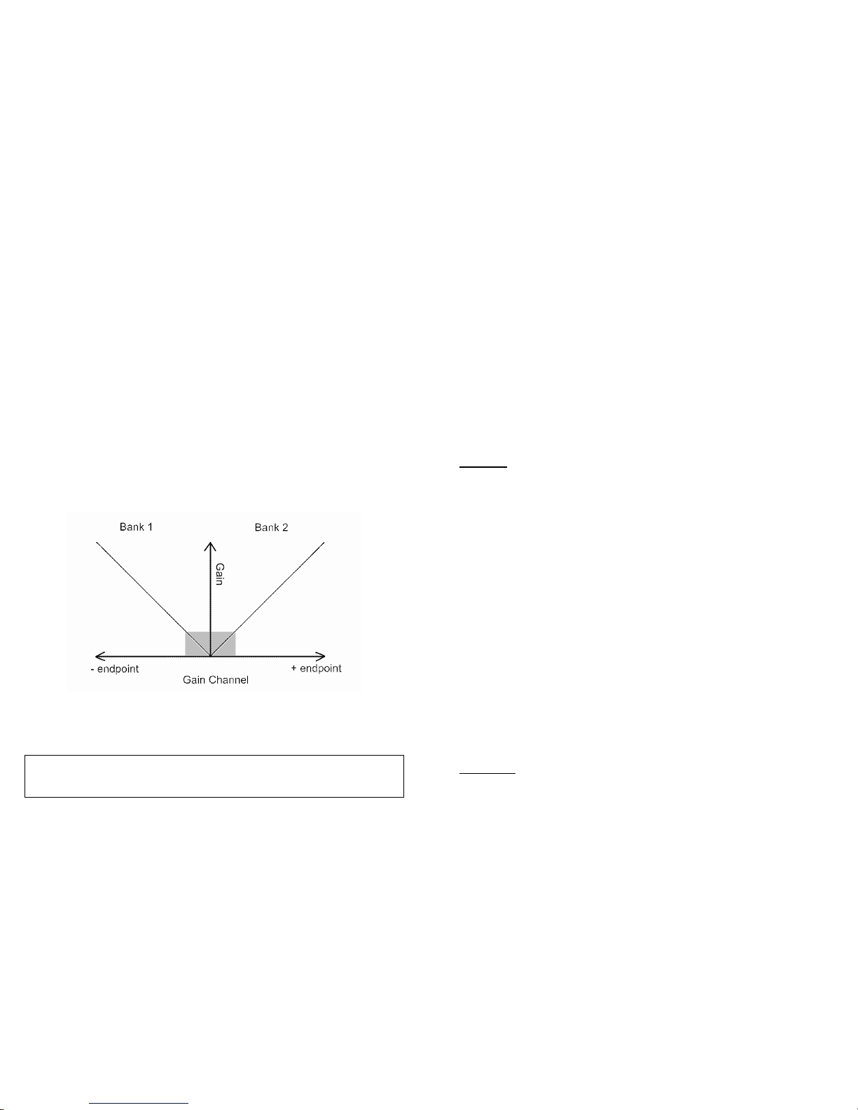
This channel also acts as a remote version of the Hiller gain dial. Negative-side
endpoint values of more than 15% on the gain channel will select Bank 1, and
positive-side endpoint values of more than 15% will select bank two.
Also note that now the Bell” dial on the case acts as the Bell Gain dial for bank 1,
and the dial labeled “Hiller” acts as the Bell Gain dial for bank 2. To learn how the
gain channel, Bell dials, and Advanced (bank) tabs work together, click “Show
Actual Gains” on one of the Advanced tabs.
You must toggle the gain channel’s switch between banks for a change
in the remote Hiller Gain to be registered.
©2008 Skookum Robotics, Ltd 16
14 USB Interface Software Reference
To use the SK360 interface software, first install the software on your PC, and plug
in the USB interface. Then attach the jumper to the gyro, set its mode switch for
setup mode, and power it up (with the motor disabled, if you have an electric heli).
On your PC, the “Connected” indicator should turn green, and the gyro’s serial
number and firmware revision should be displayed (Note: the servos may be slightly
jittery while connected to the USB port, due to noise from your computer).
If the software will not run at all, make sure your “Windows .NET Runtime” is up
to date. Check the Microsoft website for the latest version.
On the menu bar, the File menu allows you to save or load gyro configurations
(setups), or go back to the default setup. The Connect menu allows you to send a
setup to the gyro (burning it into its memory), or fetch a setup from the gyro. Any
setup sent to the gyro will be labeled with the first 8 letters of its filename.
Live Data
This area displays constantly updated telemetry from the gyro, including the control
inputs from the receiver, and position outputs to the servos. Remember that
while in setup mode, all elevator or aileron stick motions are sent directly to the
swashplate (as if stability gains were all zero, and bell gain is 100%), to allow for
easy mechanical setup.
For Inputs and Outputs, the units displayed can be percent of full throw from the
current setup, or PWM pulse-width (microseconds). Note that the collective Pitch
display should turn green for positive (climb) pitch if the gyro is set up correctly.
Under “Gyro Internals”, the Pilot Elevator and Aileron command percentage is
given as a guide for setup. It is important that cyclic stick input for nose-up, and
for right-roll, should give positive values here. Nose-up stick and right aileron
should both show green backgrounds. These readings can also be used to test the
dead-band settings.
The elevator and aileron Gyro Rates values are in degrees per second, and show the
currently sensed motion of the gyro.
The Bell Gain and Hiller Gain dial settings are displayed here for ease of
recording values arrived at by field-testing. For each type of gain, the first
percentage is the gain for elevator, the second is the gain for aileron (they’re linked
by the ratio of elevator vs. aileron for each gain on the Advanced tab of the gyro’s
setup).
Swash Tab
Swashplate Type: Select your swashplate and mechanical mixing type. Options
are 120 eCCPM, 135/140 degree eCCPM, 90 degree mechanically mixed
(separate servos for each of elevator, aileron and pitch control), and 90 degree 3

©2008 Skookum Robotics, Ltd 17
or 4 servo eCCPM, where servos are directly connected to the swash but 90
degrees apart.
Mixing: The SK360 takes over swashplate mixing, so the inputs to the gyro are
separate channels for elevator, aileron, and pitch (collective) control. This
gives the full precision of your radio set, rather than losing half of its precision
with in-transmitter mixing. It also allows for extra mixing features normally
only available on high-end radios, such as Swash Ring and Servo Equalizing.
Elevator Cyclic: Percent of full swashplate motion at full stick deflection for
elevator cyclic. This can be a negative number, but cannot be zero.
Aileron Cyclic: Percent of full swashplate servo motion at full stick deflection for
aileron cyclic. Can be a negative number, but cannot be zero.
Collective Pitch: Percent of full swashplate servo motion at full stick deflection for
collective. This can be a negative number.
Phase Trim: Rotates the plane of cyclic action about the mainshaft, to allow
correction for gyroscopic and aerodynamic effects, and the use of 3 or 4 blade
rotor heads. For example, setting phase trim to 90 degrees would make full
stick deflection for aileron tilt the swashplate down. Note that the phase angle
depends on the rotor rpm and load.
Swash Ring: Limits motion of the swashplate to prevent binding when large
amounts of both elevator and aileron cyclic are used (i.e. assume the swashplate
is round, not square).
Servo Tab
Frame Rate: The Analog servo mode synchronizes pulses to the servos with your
receiver’s output for minimum latency. Digital uses higher frame rates than
analog servos can handle and has little latency. Do not use digital frame rates
for analog servos.
Equalize Servo Speeds: Accounts for the different radius of motion for the servos
in an eCCPM swashplate arrangement. For example, for a 120-degree swash, an
aggressive pitch motion will demand higher speed from the centre servo than
the left or right servos, so it may lag behind causing uncommanded collective
input. This feature would slow all the servos evenly to the maximum rate of the
centre servo.
Servo Speed: Take this from your servo manufacturer’s specifications. Units are in
seconds per 60 degrees of motion. This helps the gyro move the swash evenly.
This field only matters if Equalize Servo Speeds is on.
Servo Travel: Amount of servo motion on either side of centre. Servo motion
outside of its mechanical limits can cause binding and overheating. The servo
travels can be set individually to trim the swash to be level at max, zero, and
min collective pitch.
©2008 Skookum Robotics, Ltd 18
Servo Trims and Reversing: Here each servo’s center point can be set, and each
can be reversed if needed. This is the same idea as sub-trim on your transmitter.
Be careful that the servo doesn’t bind.
Control Tab
Receiver/Control Setup: Similar to the settings for the servos, but here the centers
and reversing for the inputs from the radio receiver are set. To use this section,
you must first unlock it on the Options drop-down menu. Note: Features of
your radio such as exponential or pitch curves will work normally.
Use Gain Channel Input: With this feature enabled, the gyro will use A4 port as a
bank-select and hiller-gain input. The concept is similar to the way tail gyros
have a rate/heading-hold mode, with the endpoints in each direction setting the
gain for each mode.
Auto Trim at Initialization: With this feature enabled, the gyro will use the cyclic-
stick centre it receives at initialization as neutral cyclic. If left off, the gyro will
use the exact values entered in the Control tab.
Dead Band: A dead-band can be set for the cyclic (elevator and aileron) functions,
so the heli doesn’t drift with small errors in stick centering. One percent is a
good value for most radios (note your radio’s centering may change with
temperature). For scale models, deadband can give a solid control feel while in
stationary hover.
Mounting Orientation: The motion sensing directions can be flipped or rotated 90
deg, to allow the gyro to be mounted in any orientation. After mounting, always
send the setup to the gyro, and then move the heli slowly and watch Gyro Rates
on the Live Data display to be sure nose down is negative elevator rate, and
right tilt is positive aileron rate.

©2008 Skookum Robotics, Ltd 19
15 Advanced Tuning Options
The helicopter can be tuned in a more detailed way using the settings on the
Advanced tab of the USB interface program:
Maximum Rate: The desired roll or pitch rate of the heli at maximum cyclic stick
deflection. Equivalent to the area of a flybar’s paddles. If increased, Bell gain
will also need to be increased slightly.
Bell Gain: Amount of motion of the swashplate in response to cyclic stick
deflection. Normally set by a gain dial on the gyro’s case, that dial can be
disabled to lock the bell gain to a specific value.
When the gain dial is used, it will set the elevator bell gain, but the aileron
bell gain will be a fraction of that, by the ratio set here. Example: The
Advanced Tab shows Bell gains of 20% elevator and 10% aileron, and the gain
dial is not disabled. Then if the gain dial is set to 50%, the elevator bell gain
will be 50% and the aileron bell gain will be 25%.
Hiller Gains: Similar to “heading hold” on a yaw gyro. Higher Hiller Gain is
equivalent to increasing the weight of a flybar’s paddles, and adds stability and
resistance to wind gusts. This feature gives the heli a “locked-in” feel. Slop-free
linkages, rigid rotorhead mechanics, stronger servos, and stiff blades allow
higher gains here.
The Hiller gain dial is used to set the elevator and aileron hiller gains in the
same manner as described above for the Bell gain dial.
Damping Gains: Roll and pitch rate motion damping. Higher gain is equivalent to
having heavier rotor blades or a higher head speed, and helps with stability
during forward flight and pyros. Fast digital servos allow higher gain here. The
default gains are best for analog servos, but can be set to 20/16 for digital
servos. Appropriate Damping gains are normally about 1/3 as large as the Hiller
gains.
Tail Drag Compensation: All helis have uneven drag on their airframes,
especially the tail. For better piros and tick-tocks, this feature lets you trim
out the effects that has during hard collective pitch use. To use this feature,
follow these three steps:
1) Make sure your heli’s balance point is under the main shaft, or slightly
nose-heavy.
2) Check that your swash is level at min, zero, and max collective pitch while
in Setup mode. On the servo tab, first adjust the swash to be level at zero
pitch using the trims, then use the servo travels to make sure the swash is
level at min and max collective. This is needed because servos are not all
identical; the pots that measure their position can vary by 10% or more.
3) If the heli tends to nose-up when max collective is applied quickly from a
hover, subtract one from elevator tail comp. If the heli goes right, subtract
©2008 Skookum Robotics, Ltd 20
one from aileron tail comp. Add one to the fields if it noses down, or goes
left.
Hiller Decay: Causes accumulated Hiller response to decay back to neutral, to
make the gyro more forgiving of insults. If you watch a heli with a flybar in
hover, after a sharp control input you’ll see the flybar’s disk offset for a
moment, then drift back to level. This provides the same effect.
A value of 100% here can help smooth out rapid tic-tocks, piros, or other 3D
maneuvers, especially repeated ones. However, high values for Hiller Decay
will also limit the gyro’s ability to hold steady in gusty wind, or trim the heli
perfectly in hover.
Disable Gain Dials: If enabled, the gain dials on the gyro itself will have no effect.
The gains will be taken straight from those entered in the gains setup tab.
Hiller Dial Also Scales Damping Gain: If enabled, then the Hiller gain dial will
also adjust the damping gains, by the ratio of the Hiller Dial setting vs. the
elevator Hiller gain in the setup.
For example, if Elevator Hiller gain is 50% on the Advanced tab, the Hiller
Dial is set to 100%, and Damping is set to 20% for elevator on the Advanced
tab, the resulting damping gain would be 100/50*20 = 40%.
This can make it easier to re-tune the gyro when mechanical changes are
made that will affect the gains, such as to cyclic pitch or head speed.
Show Actual Gains: Brings up a table of the actual gains the SK360 will use in
flight. These gains are based on the settings on the Advanced tab, modified by
the Bell and Hiller dial’s settings. This feature can help you understand how
the gain dials and base-gains work together.
Default Gains: Resets all of the settings on the Advanced tab to those in the
Default setup file. Does not effect any settings on the other tabs.

©2008 Skookum Robotics, Ltd 21
16 Tuning Troubleshooting Guide
Symptom Problem & Solution
Heli tends to drift (feel loose) in
elevator and/or aileron. Hiller gain is too low.
Hiller gain isn’t high enough, even
at 100%. Increase cyclic blade-pitch range
using the Swash Mixing setup values,
or increase servo travel.
After a sharp elevator or aileron
command is released, the heli
oscillates slowly.
Hiller gain is too high.
While in high-speed forward flight,
the heli pitches up or down
momentarily.
Elevator damping gain is too low.
Heli tends to oscillate rapidly.
(Test by giving a sharp elevator or
aileron command, and then
release of the stick)
Damping gain is too high.
While in high-speed forward flight,
the heli sometimes oscillates in
aileron.
Aileron damping gain is too low
(Warning: too-high damping gain is
hard on servos), or Hiller is too high.
Heli hesitates in elevator and
aileron, and continues to move for
a bit when the stick is released.
Bell gain is too low relative to Control
Rates. Increase Bell gain slightly, or
decrease Control Rates.
After an elevator or aileron change
the rotor disk springs-back after
the stick is released.
Bell gain is too high relative to Control
Rates. Decrease it slightly, or
increase Control Rates.
Responds too sharply to aileron or
elevator. Bell gain is too high.
Heli precesses in hover (a motion
like a child’s spinning top as it
slows down). Gets worse with
higher Hiller gains.
Interaction between the Elevator,
Aileron, and Yaw axes. Check that
the SK360 gyro and the yaw gyro are
both mounted correctly. Also check
phase angle.
©2008 Skookum Robotics, Ltd 22
Symptom Problem & Solution
Random jitter or jumps in roll
and pitch. Vibration effects on the gyro. Make sure
it is mounted on good damping tape,
and doesn’t contact the frame. Also
check for tail vibration.
Can’t set Hiller high enough
without causing oscillation,
especially with high head
speeds.
Lack of servo speed, precision, or the
frame rate is too slow. Rotor head
mechanics should use full servo throw
for desired cyclic pitch range.
Aileron or Elevator don’t give
fast enough roll and pitch rates. Increase Control Rate gains. You will
then likely have to increase the Bell
gains slightly.
Aileron or Elevator give roll and
pitch rates that are too fast. Decrease Control Rate gains, and then
decrease the Bell gains slightly.
Cyclic feels mushy in the centre. Reduce dead-band.
Not perfectly locked in hover. Try higher dead-band.
Heli drifts slowly in elevator or
aileron with cyclic stick centered
soon after take off.
Radio receiver centering drift. Many
receivers’ center points drift with
temperature, up to 3 ticks of trim. Use
transmitter trims to correct.
Heli drifts slowly in elevator or
aileron with cyclic stick centered
after several minutes of flight.
Gyro temperature changing too quickly,
or receiver drift. Make sure the gyro and
receiver aren’t mounted near heat
sources, and let it acclimatize to field
temperature.
Heli “jumps” in pitch or roll after
hard changes between positive
and negative collective.
Check that the heli’s centre of gravity
(CG) is directly under the main shaft,
and tune swash servo throws and tail
drag compensation.
During yaw piros with collective
pitch changes, or piros during
forward flight, the heli wanders.
Damping gains are too low, servos are
not fast enough, swash moves
unevenly, or tail drag compensation
needs tuning (see page 19).

©2008 Skookum Robotics, Ltd 23
Appendix A: Specifications
Dimensions 41x31x15mm
Weight (without cables) 16 grams
Operating Temperature Range -5c to +45c
Operating Voltage 3.6 to 8.5 VDC
Power Consumption 28 mA
Wiring Gauge 22
Input Signals 3-4 Channels (PWM 700-2300 us)
Output Signals 3-4 Channels (PWM 700-2300 us)
Servo Options Analog or Digital
Setup USB interface, or by Transmitter Sticks
Field Gain Setting Bell and Hiller Gain Dials, 0 – 100%
Appendix B: Firmware Upgrades
1) Obtain the latest firmware update from www.skookumrobotics.com
2) Unzip the hex file from the compressed archive file using WinZip (or a
similar program), to a convenient directory on your PC.
3) Power it down the gyro, and connect its USB interface.
4) Load the Digital Flybar USB interface software on your PC.
5) Set the mode switch away from the gain dials (Flight mode), hold down the
option button (gently), and then power up the gyro. The LED should stay
off, and Connect on the setup screen will stay red.
6) Click the menu item Firmware, and then Update Firmware.
7) Select the hex file from step 2, and wait for the firmware upgrade to
complete.
8) When finished, the connection indicator on the PC should turn red, and the
gyro will be in Flight mode.
9) Move the mode switch towards the gain dials, and cycle the power. The
new firmware revision number should show up on the top right of the USB
interface display.
©2008 Skookum Robotics, Ltd 24
Appendix C: Warranty and Technical Support
Warranty and Repair:
Skookum Robotics Ltd warrants this product against any defects in materials or
workmanship for a period of 90 days from the purchase date. This warranty is
limited to the original purchaser. In the event of a malfunction, Skookum Robotics
will repair or replace the product to meet its standard operating condition. This
warranty does not apply in cases where the product has been overheated, electrically
shorted, subject to crash damage, otherwise abused, or had unauthorized repair
attempts.
UNDER NO CIRCUMSTANCES DOES SKOOKUM ROBOTICS ACCEPT
LIABILITY FOR INCIDENTAL DAMAGE OR INJURIES RESULTING FROM
THE OPERATION OF THE SK360 OR OTHER PRODUCTS.
Skookum Robotics will provide customers with technical assistance by email free of
charge. If a gyro is suspect due to a crash, we will check it over for only the cost of
postage. If the unit has malfunctioned and the 90-day warranty period has expired,
we will attempt repair, and discuss the cost of possible repairs with the owner, again
for only the cost of postage.
If you wish to return the gyro unit or related product, please write “WARRANTY
RETURN” clearly on the shipping box, and mail it to the address given below.
Manufactured in Canada by Skookum Robotics, Ltd
Email: [email protected]
Website: www.skookumrobotics.com
PO Box 46912 Stn D
Vancouver, BC
V6J 5M4 Canada
Table of contents
Other Skookum Toy manuals

Popular Toy manuals by other brands


SOARING MODELS
SOARING MODELS Kite 2P Assembly instruction

Fisher-Price
Fisher-Price K6779 instruction sheet

JAKKS Pacific
JAKKS Pacific Pop Sing Scene 3559 brochure

Topmodel CZ
Topmodel CZ MDM 1 FOX De-luxe quick guide

LEGO
LEGO Architecture Imperial Hotel 21017 Building instructions

NOCH
NOCH Raised Hide quick start guide


