SKP Pro Audio VZ-5 User manual

VZ-5
5 CHANNEL STEREO MIXER
ENGLISH OWNER MANUAL

-1-
INPUT CHANNEL SECTION----------------------------------------------------------------------3
MASTER SECTION----------------------------------------------------------------------------------4
POWER SECTION------------------------------------------------------------------------------------5
INSTALLATION----------------------------------------------------------------------------------------5
CONNECTIONS----------------------------------------------------------------------------------------7
APPENDIX-----------------------------------------------------------------------------------------------8
BLOCK DIAGRAM-------------------------------------------------------------------------------------9
-2-
Ultra low noise 5 Channel Mic / Line Mixer
1 Mono Input Channels with silver plated XLRs and balanced Line Inputs
2 Stereo Input Channels with balanced TRS Jacks
Balanced Inputs for highest signal integrity
Ultra-musical 2-band EQ on all channels
1 Aux Send per channel for external effects and monitoring
Highly accurate 4 segment Bargraph Meters
Rugged design Power Supply ensures superior signal integrity
SAFETY INSTRUCTIONS
CAUTION: To reduce the risk of electrical shock, do not remove the cover
(or back). No user serviceable parts inside; refer servicing to qualified
personnel.
WARNING: To reduce the risk of fire or electrical shock, do not expose this
appliance to rain or moisture.
This symbol, wherever it appears, alerts you to the presence of
uninsulated dangerous voltage inside the enclosure - voltage
that may be sufficient to constitute a risk of shock.
This symbol, wherever it appears, alerts you to important
operating and maintenance instructions in the accompanying
literature. Read the manual.
-3-
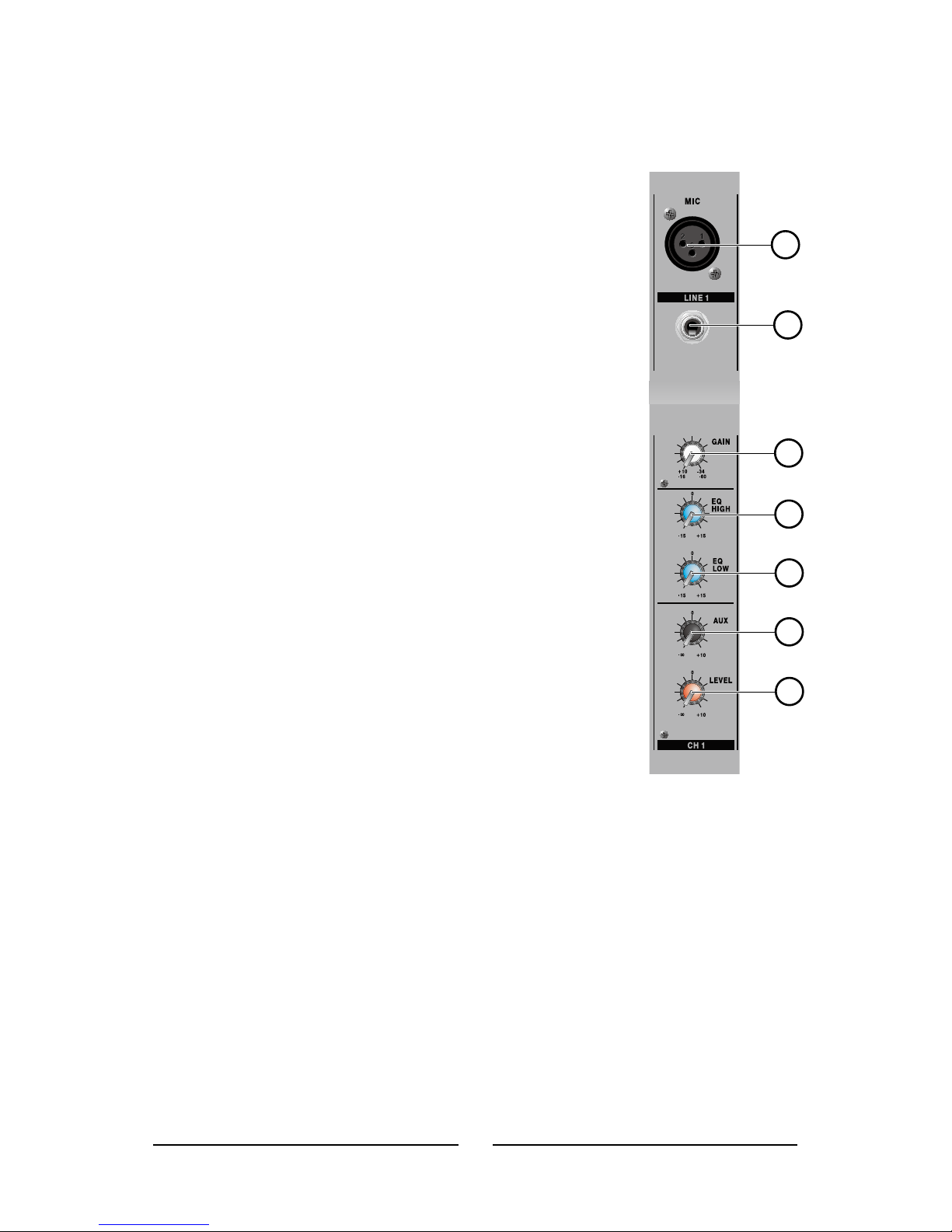
A. IN PUT CHANNEL SECTION
1. XLR Microphone Jacks
These jacks accept typical 3-pin XLR inputs for
balanced and unbalanced signals. They can be used in
conjunction with microphones- such as professional
condenser, dynamic or ribbon microphones - with
standard XLR male connectors, and feature low
noise preamplifiers, serving for crystal clear sound
replication.
2. LINE INPUT
This input accepts typical 1/4” TRS or TS inputs,for
balanced or unbalanced signals. There are various numbers
of these inputs depending which mixer you are using. They
can be used in conjunction with various line level devices,
such as keyboards, drum machines, electric guitars, and a
variety of other electric instruments.
3. GAIN
This controls the sensitivity of the input signal of
the The Line/Microphone input. The gain should be
adjusted to a level that allows the maximum use of
the audio, while still maintaining the quality of the feed. This can be ac-
retucomplished by adjusting a level input that will allow the peak indicator
occasionally illuminate.Adjusts input sensitivity from -60dB to -16dB in the
out position, and -34dB to +10dB is pushed.
4. HIGH
This control is used to give shelving boost or cut of +15 dB to high
frequency (12 kHz) sounds. This will adjust the amount of treble included in
the audio of the channel, adding strength and crispness to sounds such as
guitars, cymbals, and synthesizers.
1
2
3
4
5
6
7

-4-
5. LOW
This control is used to give a shelving boost or cut+/-15 dB to low
frequency (80 Hz) sound.This will adjust the amount of bass included in the
audio of the channel,and bring more warmth and punch to drums and bass
guitars.
6. Aux
These controls alter the signal level that is being sent to the auxiliary
mixing buses, the signal of which is suitable for connecting stage monitors,
allowing artists to listen to the music that is being playing.
7. CHANNEL VOLUME
This is function to adjust the volume of signal connection into each channel
and adjust the volume of output, together with master fader. Normal
operating position is at the "0" mark
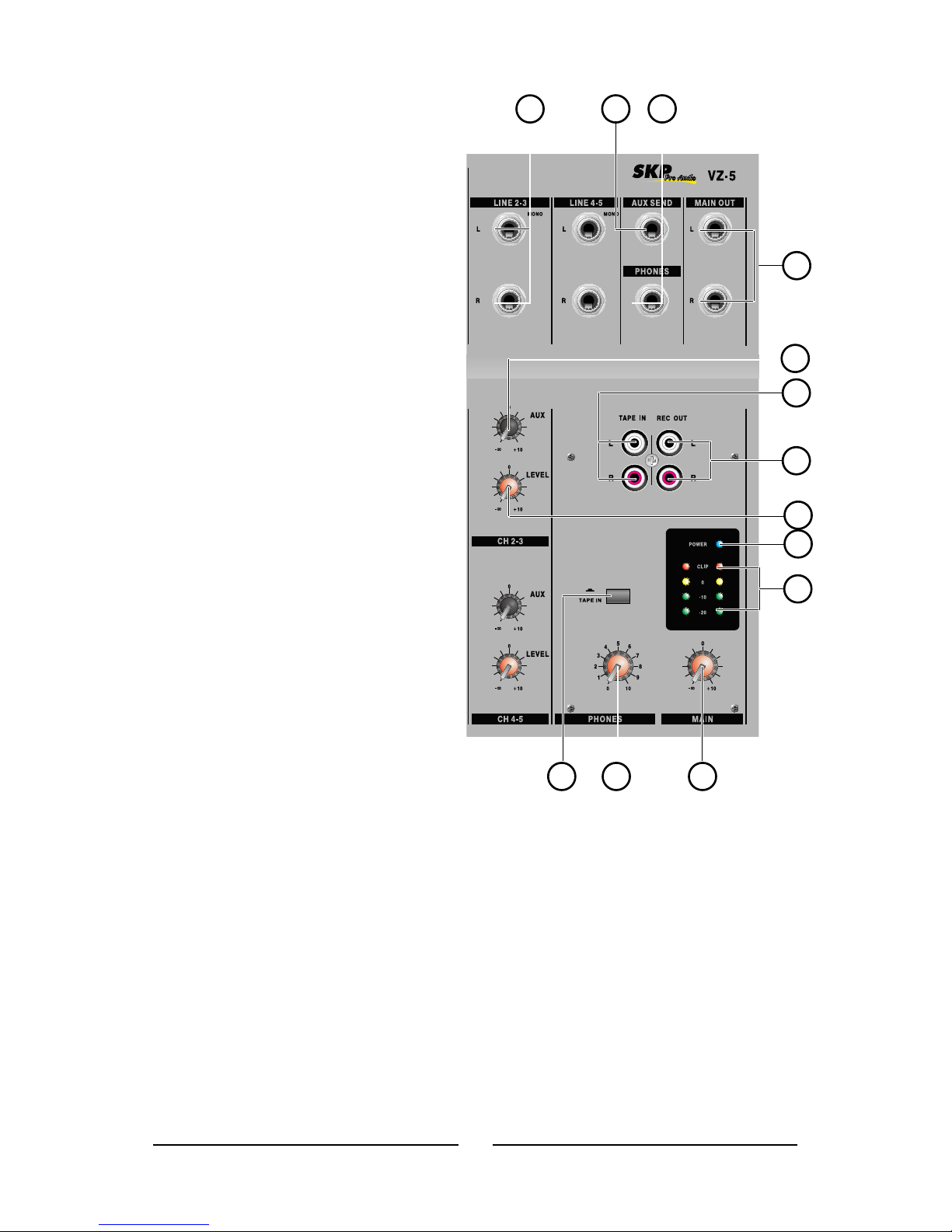
B. MASTER SECTION
8. LEFT (MONO) / RIGHT
Line with connection 1/4 jack as line input of L,R stereo and input the
signal of balance line level. If the signal input into the input terminal of left
side, output the mono output to left & right side. If the signal input the
input terminal of right side, output into the right side only. If each signal
input the input terminal of left & right, output a stereo of left & right.
9. AUX
These controls alter the signal level that is being sent to the auxiliary
mixing buses, the signal of which is suitable for connecting stage monitors,
allowing artists to listen to the music that is being playing.
10. STEREO CHANNEL VOLUME
This is a function to adjust the volume of signal connection into each
channel and adjust the volume of output, together with master fader.
Normal operating position is at the “0” mark.
-5-
11. Tape In (L and R)
T h e f i rs t o f t h e s e i n p u t s
accommodates RCA cables from
such devices as tape and CD
players. The line from this feed
is directed to the Tape In mixing
bus, before being fed through to
the Main L/R mixing bus.
12. Record Outputs (L and R)
As with the Tape In ports, these
outputs will accommodate RCA
cables, able to be fed to a variety
of recording devices.
13. TAPE IN
Press this switch , you can input
the Tape signal to the mix L-R
through.
14. POWER LED
The POWER LED will be turned
on when start working.
15. OUTPUTS LEVEL INDICATOR
This is level meter which shows output levels of left & right channel
condition on the of operation. Therefore, you can see output condition thru
this master level indication.
16. PHONES
This knob controls the level of the audio to be sent to the PHONES Output.
17. OUTPUT MASTER FADER(LEFT/RIGHT)
This is a master fader for adjustment for volume of left/right output. Unity
gain is the top their travel .
20
818 19
9
10
11
12
16 17
14
15
13

-6-
18. AUX SEND JACK
This is a send output jack.
19. PHONES
This stereo output port is suited for use with headphones, allowing
monitoring of the mix. The audio level of this output is controlled using the
Phones/Control Room control.
20. STEREO OUTPUT JACK (LEFT / RIGHT)
In this product, the final confirmed sound can be send to main amplifier
through 1/4 jack.
C. POWER SECTION
21. POWER SWITCH
Push marked (ON), when you want to operate. The LED (SEE NO, 14) will
be turned on when working.
22. POWER JACK
This is out of connect the power supply (2 X AC 18V) jack.
D. INSTALLATION
Experience tells us that the cables in a studio environment get tangled very
quickly (inviting mistakes).
22 21
-7-
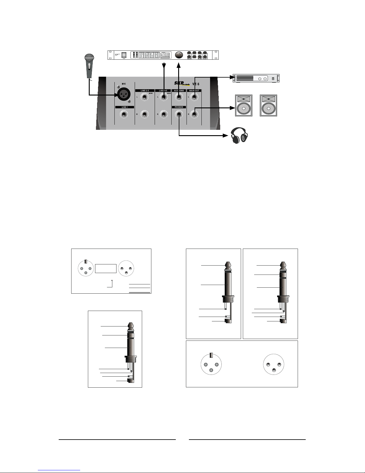
E. CONNECTIONS
You will need a lot of cables for different purposes - see the following
figures to make sure you have got the right ones. Unbalanced equipment
may be connected to balanced inputs/outputs. Either use mono 1/4" jacks
or connect ring and sleeve of TRS jacks.
Headphone connection
Tip =
Left signal
Sleeve =
Ground / Shield
Tip
Sleeve
Strain relief clamp
Headphones
Ring =
Right signal
Ring
Compensation of interference with balanced connections
21
3
Output
Pin 1
Pin 2 = (+) Signal
Pin 3 = (-) Signal
12
3
RFI and Hum
Shield
(+) Signal + Hum
(-) Signal + Hum
Cable Input
Ground
Pin 2 = (+)Hum + Signal
Pin 3 =(-)Hum + Signal
2 x Signal
= Signal + 6 dB
Different plug types
Unbalanced use of
mono 1/4" jack plugs
Tip =
Signal
Sleeve =
Ground / Shield
Tip
Sleeve
Strain relief clamp
Balanced use of
Tip =
hot (+ve)
Sleeve =
Ground / Shield
Tip
Sleeve
Strain relief clamp
stereo 1/4" jack plugs
Ring =
cold (-ve)
Ring
For connection of balanced and
unbalanced plugs, ring and sleeve have
to be bridged at the stereo plug.
21
3
12
3
Balanced use with XLR connectors
1 = /
Ground Shield
2 = hot (+ve)
3 = cold (-ve)
1 3
For unbalanced use pin and pin have to be bridged
Input Output

-8-
F. APPENDIX
Specications
Inputs
Total Channels
Balanced Mono Mic / Line
Channel
Stereo Line Channel
Tape Input
Outputs
Main L/R Stereo
Phones
AUX Send
Channel Strips
Volume Controls
Master Section
Phones Level Control
Main L/R Level Control
Metering
Number of Channels
Segments
Frequency Response (Mic
input to any output)
20Hz- 20KHz
20Hz- 100KHz
Crosstalk (1KHz OdBu, 20Hz
to 20KHz bandwidth, channel
in to main L/R outputs)
Channel fader down, other
channels at unity
S/N
Microphone Preamp E.I.N. (150
ohms terminated, max gain)
THD (Any output, 1KHz +14dBu,
20Hz to 20KHz, channel inputs)
CMRR (1 KHz - 6OdBu, Gain at
maximum)
Maximum Level
Mic Preamp Input
All Other Input
Balanced Output
Impedance
Mic Preamp Input
All Other Input (except insert)
REC Output
Equalization
Low EQ
HiEQ
Power Adaptor (external power
supply, depends on region)
3
1
2
Stereo RCA
2x 1/4” TS, Bal
1
3
Rotary
Yes
Rotary VR
2
4
+0/-1 dB
+0/-3 dB
>90 dB
>90 dB
<-129.5 dB
<0.01%
80 dB
+6 dBu
+22 dBu
+28 dBu
3 K ohms
10 K ohms
1.6 K ohms
2-band,+/-15 dB
80 Hz
12 KHz
100V AC,120V AC
220-240V AC
50/60Hz IN,
Out put 18V AC
500mA
1

-9-
G. BLOCK DIAGRAM
RIGHT METER
EQ
LEFT METER
2 BAND
+60dB
44dB
+10dB
+10dB
+10dB
+10dB
+10dB
+10dB
+10dB
+/-15dB
MAIN L MAIN L
AUX
MAIN R
MAIN R
AUX
MAIN R
CH1 Line
LOW
CH1 Mic.
1 2
3
PHONES
TAPE/L
1
2
REC OUT/L
1
2
MAIN
GAIN TAPE/R
1
2
CH 3/5 Input
TO MAIN
CH 2/4 Input
LEVEL
PHONES
MAIN L
HIGH
TAPELEVEL
REC OUT/R
1
2
AUX SEND
AUX
AUX


WWW.SKPAUDIO.COM
Table of contents
Other SKP Pro Audio Music Mixer manuals


