SKP Pro Audio CRX-1010 User manual

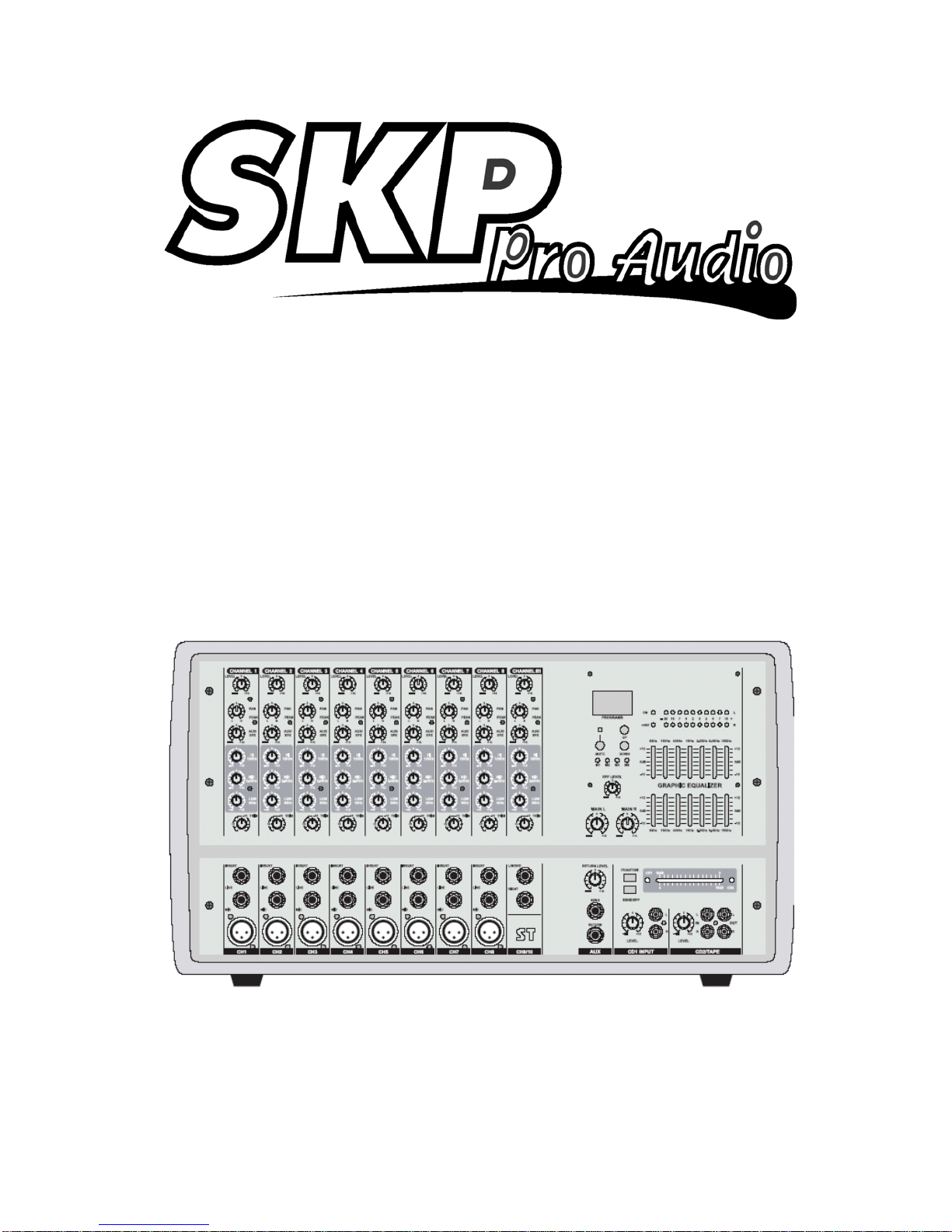
CRX-1010
MIC/LINE MIXER
10 CHANNEL
OWNERS MANUAL

A. INPUT CHANNEL SECTION
B. STEREO CHANNEL SECTION
C. MASTER SECTION
D. POWER SECTION
E. INSTALLATION
F. CONNECTIONS
G. APPENDIX
H. BLOCK DIAGRAM
2~3
4~5
6~7
8
8
9~10
11
12

1
8 Mono Input Channels with sliver plated XLRs and balanced Line Inputs
Ultra-low noise discrete Mic Preamps with +48 V Phantom Power
1 Stereo Input Channels with balanced TRS Jacks
2 CD Input Channels
Extremely high headroom - offering more dynamic range
Balanced Inputs for highest signal integrity
Ultra-musical 3-band EQ on all channels
Peak LEDs all Mono and Stereo Channels
1 Aux Sends per channel for external effects and monitoring
256 DSP system inside
Highly accurate 10 segment Bargraph Meters
Separate master mix output
Ultra low noise 10 - Channel Mic / Line Mixer
SAFETY INSTRUCTIONS
CAUTION: To reduce the risk of electrical shock, do not remove
the cover (or back). No user serviceable parts inside;
refer servicing to qualified personnel.
WARNING: To reduce the risk of fire or electrical shock, do not
expose this appliance to rain or moisture.
CAUTION
RISK OF ELECTRIC SHOCK
DO NOT OPEN
This symbol, wherever it appears, alerts
you to the presence of uninsulated
dangerous voltage inside the enclosure
- voltage that may be sufficient to con-
stitute a risk of shock.
This symbol, wherever it appears, alerts
you to important operating and mainte-
nance instructions in the accompanying
literature. Read the manual.
A. INPUT CHANNEL SECTION
6
5
2
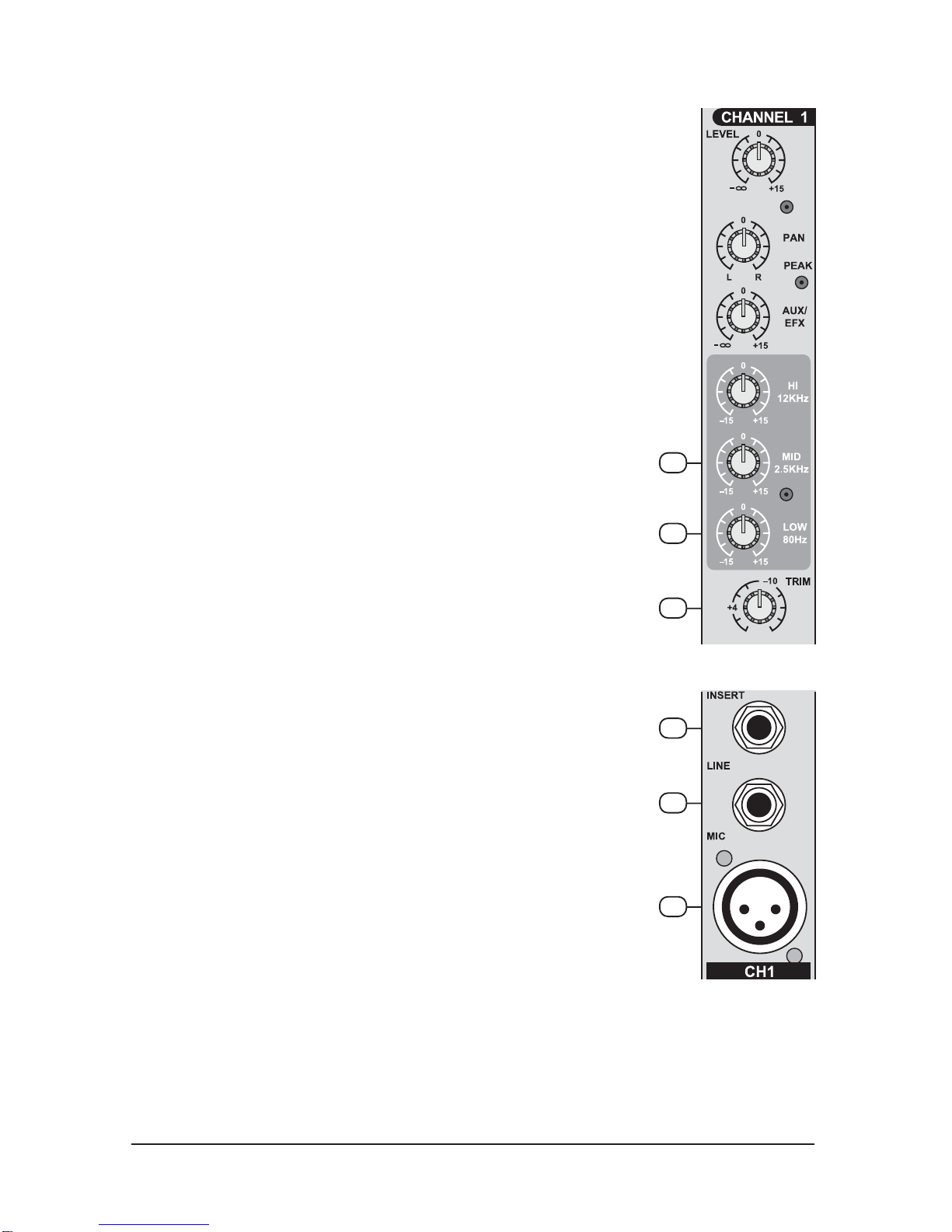
2. LINE INPUT
The unbalanced Mic input is provided for the use of an unbalance
mic and is designed to accept an unbalanced high impedance
input signal.
(This use for connection Deck, Turntable, Keyboard etc..)
1. BALANCE INPUT (MIC)
Electronially Balanced inputs acceptable a standard XLR male
connector.
+ 48V Phantom Power available on each input Mic socket.
and this switch is on Rear Phantom Power.
4
3
2
1
3. INSERT
The INSERT is a break point in the input channel signal path. It
allows the signal to be taken out from the mixer, through an
external equipment such as a compressor, and then back to the
mixer to continue the final mix output.
4. TRIM
This has a function which adjusts the input sensitivity of each
channel in order to input the constant level of the signal.
6. MID EQ
Short for “midrange”, this knob provides 12 dB of boost or cut,
centered at 2.5KHz, also flat at the center detent. Midrange EQ is
often thought of as the most dynamic, because the frequencies
that define any particular sound are almost always found in this
range. You can create many interesting and useful EQ changes
by turning this knob down as well as up.
5. LOW EQ
This control gives you up to 15 dB boost or cut at 80Hz and below.
This circuit is flat (no boost or cut) at the center detent position.
This frequency reptesents the punch in bass drums, bass guitar,
fat synth patches, and some really serious male singers.

3
11
8. AUX/EFF
This is normally derived after the EQ and channel fader (POST
FADER, POST EQ), and is therefore follow any changers in fader
level. They are normally used to drive effects processing units
which are fed back into the mixer and which must fade out with the
input channel.
9. PAN
The pan control sends continuously variable amounts of the post
fader signal to either the left or righ main busses. In the center
position equal amounts of signal are sent to the left and right
busses.
10. PEAK
A red LED indicates a signal level at the insert return point,
premaster fader, It illuminates at approximately 5dB below clipping.
11. CHANNEL FADER
This is function to adjust the volume of signal connection into each
channel and adjust the volume of output, together with master
fader. Normal operating position is at the “O” mark, providing 4dB
of gain adove that point, if required.
9
10
8
7
7. HI EQ
This control gives you up to 15 dB of boost or cut at 12KHz and
above, and it is also flat at the detent. Use it to add sizzle to
cymbals, and an overall sense of transparency or edge to key-
boards, vocals, guitar, and bacon frying. Turn it down a little to
reduce sibilance, or to hide tape hiss.
15
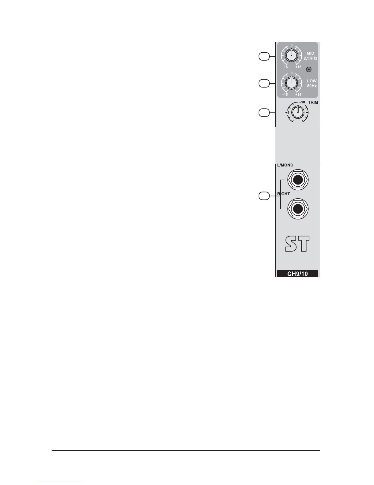
12. LEFT (MONO) / RIGHT
Line with connection 1/4 jack as line input of L, R stereo and input
the signal of balance line level. If the signal input into the input
terminal of left side, output the mono output to left & right side. If
the signal input the input terminal of right side, output into the right
side only.
If each signal input the input terminal of left & right, output a stereo
of left & right.
B. STEREO CHANNEL SECTION
4
14
13
12
13. TRIM
This has a function which adjusts the input sensitivity of each
channel in order to input the constant level of the signal.
15. MID EQ
Short for “midrange”, this knob provides 12 dB of boost or cut,
centered at 2.5KHz, also flat at the center detent. Midrange EQ is
often thought of as the most dynamic, because the frequencies
that define any particular sound are almost always found in this
range. You can create many interesting and useful EQ changes
by turning this knob down as well as up.
14. LOW EQ
This control gives you up to 15 dB boost or cut at 80Hz and below.
This circuit is flat (no boost or cut) at the center detent position.
This frequency reptesents the punch in bass drums, bass guitar,
fat synth patches, and some really serious male singers.
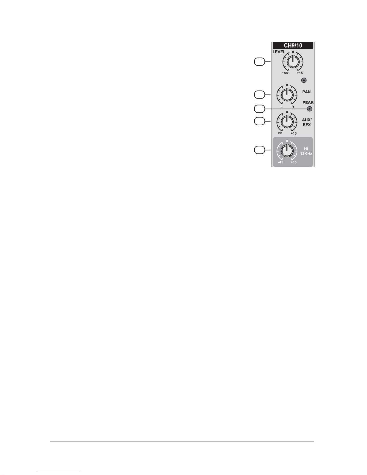
20. STEREO CHANNEL FADER
This is a function to adjust the volume of signal connection into
each channel and adjust the volume of output, together with
master fader. Normal operating position is at the “0” mark,
providing 4dB of gain adove that point, if required.
5
20
18
19
17
16
17. AUX/EFF
This is normally derived after the EQ and channel fader (POST
FADE, POST EQ), and is therefore follow any changers in fader
level. They are normally used to drive effects processing units
which are fed back into the mixer and which must fade out with the
input channel.
18. PAN
The pan control sends continuously variable amounts of the post
fader signal to either the left or right main busses. In the center
position equal amounts of signal are sent to the left and right
busses.
19. PEAK
A red LED indicates a signal level at the insert return point,
premaster fader, It illuminates at approximately 5dB below clipping.
16. HI EQ
This control gives you up to 15 dB of boost or cut at 12KHz and
above, and it is also flat at the detent. Use it to add sizzle to
cymbals, and an overall sense of transparency or edge to key-
boards, vocals, guitar, and bacon frying. Turn it down a little to
reduce sibilance, or to hide tape hiss.
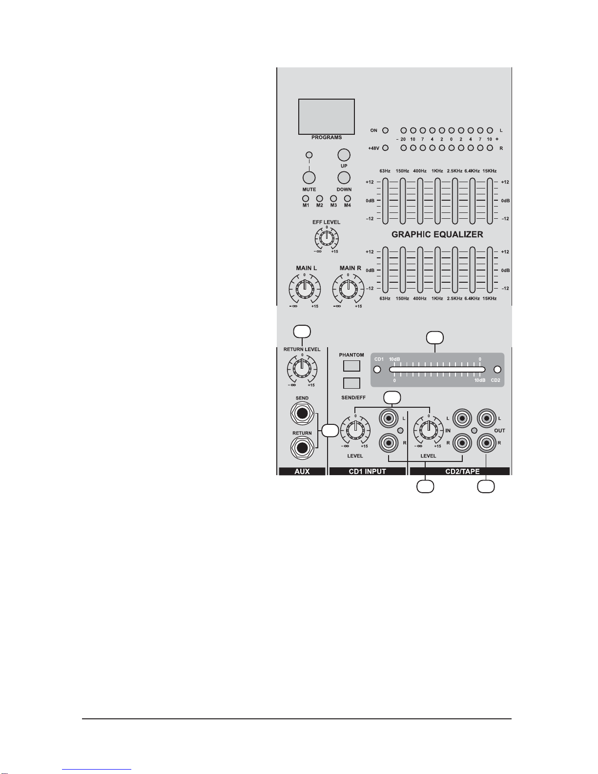
C. MASTER SECTION
21
22
23
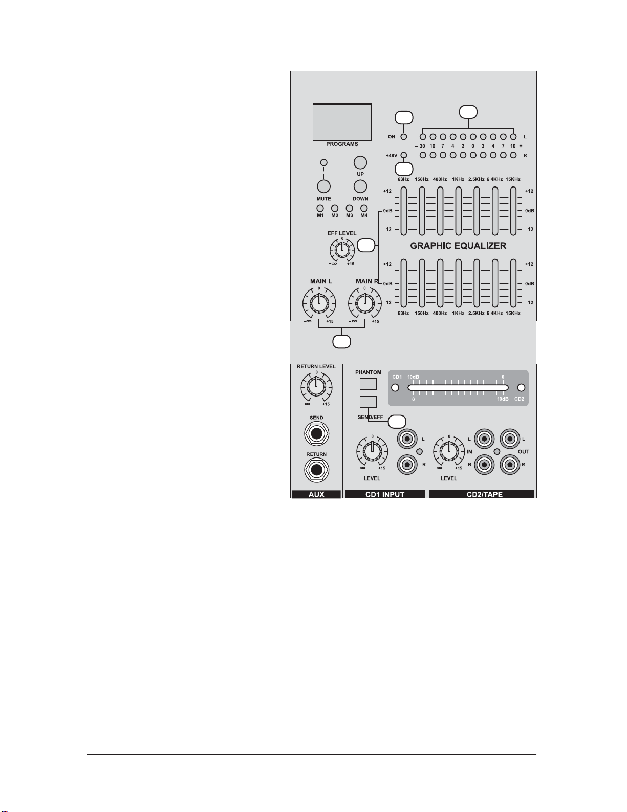
26. SEND/EFX
When this button is up, post signal
work as send, when this button is
down, post signal work as effect
signal.
21. POWER LED
The POWER LED will be turned on
when strt working.
22. PHANTOM LED
The LED +48V will be turned on
when strt working.
25. MASTER FADER
(LEFT/RIGHT)
This is a master fader for adjustment
for volume of left/right output. Unity
gain is the top their travel.
23. OUTPUTS LEVEL INDICATOR
This is level meter which shows
output levels of left & right channel
condition on the way of operation,
therefore, you can see output
condition thru this master level
indication.
24. STEREO GRAPHIC
EQUALIZER
2X7-band equalizer is provided for
tone control over each frequency,
and for precise high quality sound by
final tone control.
24
25
26
6
27
29
30
31
32
7
28. AUX RETURNS & SENDS
This can be used to connect all kinds
of effects from outside.
32. RECORD PIN JACK
This jack is to be connected with
cassette deck when recording the
mixed output.
27. AUX RETURN LEVEL
This is used for adjusting volume of
aux sound, when sending and return
aux singal to used jack.
28
29. CD IN LEVEL
You can adjust the volume of CD in
signal by this when connecting line
in.
30. CD INPUT JACK
This jack is to be connected with
cassette deck when playing Jack.
31. CD (1/2) CHANNEL
CONVERSION FADER
This is a fader to control the
conversion of CD1, CD2 stereo
channel. When it's pushed on the
left side, CD1 channel is working;
right side CD2 working. If it's on the
center, CD1 & CD2 are on working
at the same time & get the sam gain.
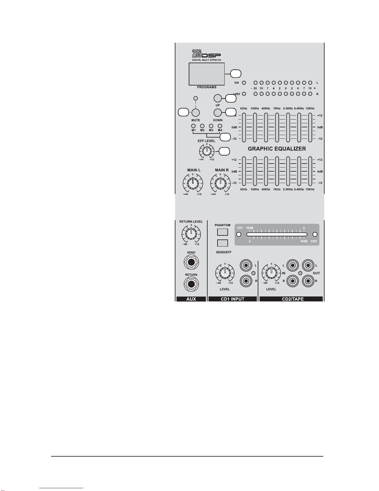
256DSP SECTION
A
C
D
F
B
E
A. EFFECT PROGRAMS
INDICATE 256 Digital multi Effects.
F. EFFECT LEVEL
Using by this control, you can adjust
signal level of echo repeat & exteral
effect.
B. MUTE
Effect ON/OFF.
D. DOWN TAPE SWITCH
One push, one program down, push
with more than 5 seconds, hi-speed
program down.
C. UP TAPE SWITCH
One push, one program up push with
more than 5 seconds hi-speed
program up.
E. Pre-set
Push more than 5 seconds, It
automatacally memorize the displayed
program number. Once Just Push
M1. M2. M3. M4, always display
memorized program.
8
9
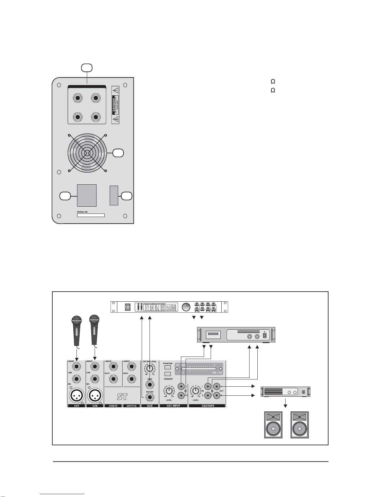
D. POWER SECTION
33
Experience tells us that the cables in a studio environment get tangled very quickly (inviting
mistakes).
E. INSTALLATION
MODEL-DVP-3000
AMPLIFIER
DIGITAL
LRdB
-6
-3
-1
0
+1
+3
+6 SURROUND
01
02
03
04
05
06
07
08
09
10
11
12
13
14
15
16
17
18
19
20
21
22
23
24
25
26
27
28
29
30
31
32
POWER
TAPE
OUTPUT
L & R
INPUT
L & R
RIGHT
SPEAKER OUTPUTS
LEFT
A
B
A
B
AC IN / FUSE POWER
3435
36
34. POWER SWITCH
Push marked (I), when you want to operate. The LED (21)
will be turned on when working.
35. AC POWER CORD/FUSE HOLDERS
AC 220~240V 50~60Hz or 120V 60Hz Check the power
source of ac 220V before connections. When occur a
provlem on this appliance, the fuse will be cut off power to
prevent form aproblem.
36. FAN
In order tp prevent rising the inside temperature, the inside
heat is emitted outside.
33. SPEAKER JACK (LEFT / RIGHT)
This is a amplifier output jack.
12 CHANNEL MIXER: 350W+350W 4
16 CHANNEL MIXER: 350W+350W 4
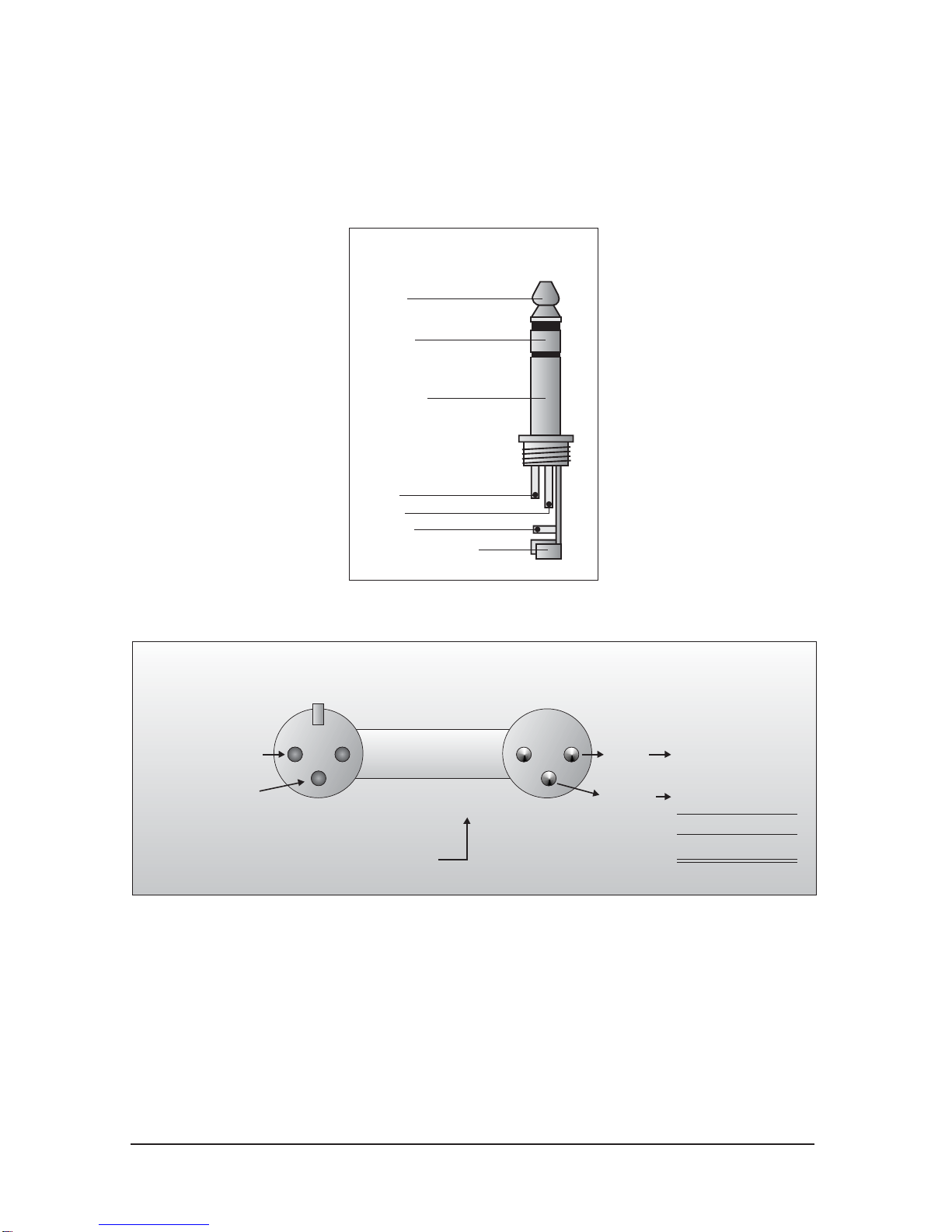
You will need a lot of cables for different purposes - see the following figures to make sure you have got the
right ones. Unbalanced equipment may be connected to balanced inputs/outputs. Either use mono 1/4" jacks
or connect ring and sleeve of TRS jacks.
Fig.
6
.
1
:
Headphone connection
Fig.
6
.
2
:
Compensation of interference with balanced connections
Tip =
Left signal
Sleeve =
Ground / Shield
Tip
Sleeve
Strain relief clamp
Headphones
Ring =
Right signal
Ring
21
3
Output
Pin 1
Pin 2 = (+) Signal
Pin 3 = (-) Signal
12
3
RFI and Hum
Shield
(+) Signal + Hum
(-) Signal + Hum
Cable Input
Ground
Positive
Negative
(+)Hum + Signal
(-)Hum + Signal
2 x Signal
= Signal + 6 dB
10
F. CONNECTIONS

11
Fig. 6.3 : Different plug types
Unbalanced use of
mono 1/4" jack plugs
Tip =
Signal
Sleeve =
Ground / Shield
Tip
Sleeve
Strain relief clamp
Balanced use of
Tip =
hot (+ve)
Sleeve =
Ground / Shield
Tip
Sleeve
Strain relief clamp
stereo 1/4" jack plugs
Ring =
cold (-ve)
Ring
For connection of balanced and
unbalanced plugs, ring and sleeve have
to be bridged at the stereo plug.
21
3
12
3
Balanced use with XLR connectors
1 = Ground / Shield
2 = hot (+ve)
3 = cold (-ve)
For unbalanced use pin 1 and pin 3 have to be bridged
Input Output

Mono Inputs
Specifications
Mic Input
Bandwidth
Distortion (THD & N)
Mic E.I.N (22 Hz - 22 kHz)
TRIM range
electronically balanced, discrete input configuration
10 Hz to 60 kHz ± 3 dB
0.01% at +4 dBu, 1 kHz, Bandwidth 80 kHz
-129.5 dBu, 150 Ohm source
-117.3 dBqp, 150 Ohm source
-132.0 dBu, input shorted
-122.0 dBqp, input shorted
+10dB to +60dB
Line Input
Bandwidth
Distortion (THD&N)
Line level range
electronically balanced
10 Hz to 60 kHz ± 3 dB
0.01% at +4 dBu, 1 kHz, Bandwidth 80 kHz
+10 dBu to -40 dBu
Equalization
Hi Shelving
Mid Range
Lo Shelving
12 kHz +/-15 dB
2.5 kHz +/-15 dB
80 Hz +/-15 dB
Steroe inputs
Line Input
Bandwidth
Distortion (THD & N)
unbalanced
10 Hz to 55 kHz ±3 dB
0.01% at +4 dBu, 1 kHz, bandwidth 80 kHz
Equalization
Hi Shelving
Mid bell
Lo Shelving
Lo Cut (High Pass) filter
12 kHz +/-15 dB
100Hz -8KHz +/- 15dB, Q fixed at 1 oct
80 Hz +/-15 dB, Q fixed 2 oct
-3dB at 75Hz, 18dB / oct
Master Mix section
Max Output
Aux Send Max Out
Control Room Out
Signal-To-Noise Ratio
+22 dBu balanced
+22 dBu unbalanced
+22 dBu unbalanced
112 dB, all channels at Unity Gain
Power supply
Mains Voltages USA/Canada
U.K./Australia
China
120V 60Hz
240V 50Hz
220V 50Hz
12
G. APPENDIX
13
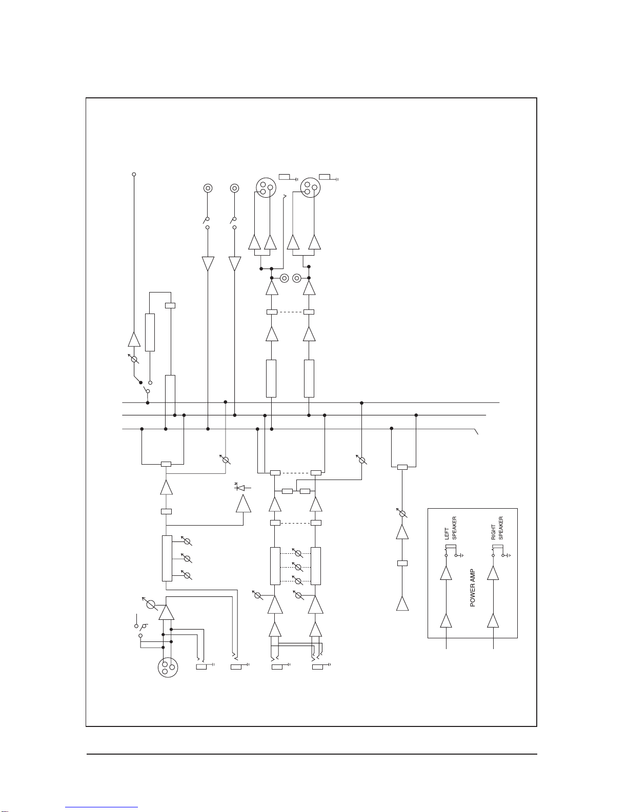
H. BLOCK DIAGRAM
+48V
LINE
MIC
PH
TRIM
HI MID
3-EQ
PAN
FADER
L
PEAK
AUX
R
3-EQ
EQ
INSERTS
STEREO INPUT
L
R
FADER
H MID LO
BAL
AUX
R
L
STEREO AUX RETURN
L
R
L
CD IN
R
LEFT
MAIN MIX
RIGHT
REC
FADER
MIAN
MONO INPUT CHANNELS
LO
AUX
AUX RETURN
RETURN
7 EQ
7 EQ
256 DSP
FADER
SEND
CRX-1010
MEZCLADORA MIC/LINE
10 CANALES
MANUAL DE USUARIO

A. SECCION CANALES DE ENTRADA----------------------------------------------------------------------2-3
B. SECCION CANALES STEREO-----------------------------------------------------------------------------4-5
C. SECCION MASTER -------------------------------------------------------------------------------------------6-7
D. SECTION POTENCIA--------------------------------------------------------------------------------------------8
E. INSTALACIÓN------------------------------------------------------------------------------------------------------8
F. CONEXIONES--------------------------------------------------------------------------------------------------9-10
G. APENDICE---------------------------------------------------------------------------------------------------------11
H. DIAGRAMA DE BLOQUE--------------------------------------------------------------------------------------12
•Mezcladora de 10 Canales de Mic / Line
•8 Canales Mono con XLR y Entradas de Línea Balanceadas
•1 Entrada estéreo con Jacks 1/4 balanceado
•Pre-amplificador de Micrófono discretos con phantom power de +48 V
•2 entradas de CD
•Gran rango dinámico
•Entradas Balanceadas para una mejor señal
•EQ de 3 bandas en todos los canales
•LED de clip en todos los canales
•Envío de Auxiliar por canal para efectos externos y monitoreo
•Sistema DSP de 256 efectos incorporado
•VU de 10 segmentos muy precisos
•Salida Master y salida de grabación

INSTRUCCIONES DE SEGURIDAD
- Seleccione el lugar para la instalación de su unidad, cuidadosamente
- Evite instalarla donde reciba luz solar directa
- También evite lugares sujetos a vibración, excesos de polvo, calor,
frío o humedad
- Mantenga el equipo, lejos de fuentes de zumbido, tales como
transformadores o motores.
- No abra el gabinete ya que puede causar daños al equipo ó choque
eléctrico
- Al desconectar el cable de alimentación, del tomacorriente, siempre
agárrelo
de la ficha. Nunca tire del cable.
- No use la fuerza al operar perillas, teclas y botones.
- Antes de mover el equipo, asegúrese de desconectar el cable de
alimentación
y todos los cables de conexión.
- No use solventes químicos para limpiar la unidad, porque puede dañar su
acabado.
Para su limpieza, utilice un trapo limpio y seco.
- No exponga el aparato a goteos ni a salpicaduras, y no coloque sobre el,
objetos que contengan líquidos.
- El equipo deberá ser conectado a un tomacorriente con conexión a tierra,
para protección personal. Recomendado para equipos Clase I
- El tomacorriente donde se conecta el equipo, deberá estar ubicado cerca de
este,
para fácil acceso.
- Guarde este manual en lugar seguro para futuras referencias.
PRECAUCION: Para reducir el riesgo de descarga eléctrica, no quite la cubierta o parte posterior.
No hay partes útiles de usuario adentro; para servicio acudir solo a personal calificado
.
ADVERTENCIA: Para reducir el riesgo de incendio o descarga eléctrica, no exponga este aparato a
la lluvia o la humedad.
OF E Este símbolo, donde quiera que aparezca, lo alerta de la presencia de voltaje
peligroso adentro del cuerpo del aparato, voltaje lo suficientemente alto para constituir un riesgo de
descarga.
LECTRIC SHOCK
DO NOT OPEN
Este símbolo, dondequiera que aparezca, alerta de importantes instrucciones
operativas y de mantenimiento, que acompañan la literatura. Lea el manual.

A. SECCION CANALES DE ENTRADA
1. ENTRADA BALANCEADA (MIC)
Las entradas de Mic des-balanceados están hechas para el uso
de un mic No-balanceado y diseñadas para aceptar una señal de
alta impedancia.
2. ENTRADAS BALANCEADAS (MIC)
Las entradas electrónicamente balanceadas aceptan un conector
macho XLR.
Los + 48V de el phantom power está disponible en cada socket
de Mic.
3. INSERTAR
El INSERT es un desvío de la señal de entrada del canal.
Permite que la señal sea sacada de la mezcladora y enviada a
un equipo externo como un compresor, y luego retornar a la
mezcladora para continuar la mezcla.
.
4. TRIM
Tiene una función que ajusta la sensibilidad de entrada de cada
canal para tener un nivel constante y equilibrado de señal.
5. BAJOS
Este control aumenta o disminuye en15 dB la frecuancia de
80Hz.
Siempre coloque este control la posición central y a partir de ahí
controle el tono de acuerdo al alta voz, las condiciones de la
posición de escuchar, y el estado del que escucha. Hacia la
derecha el control incrementa el nivel
6. MEDIOS
Este control aumenta o disminuye en 12 dB la frecuancia de
2.5KHz.
Siempre coloque este control la posición central y a partir de ahí
controle el tono de acuerdo al alta voz, las condiciones de la
posición de escuchar, y el estado del que escucha. Hacia la
derecha el control incrementa el nivel

7. AGUDOS
Este control aumenta o disminuye en 15 dB la frecuancia de 12KHz y, y es
también chato en Siempre coloque este control la posición central y a partir de
ahí controle el tono de acuerdo al alta voz, las condiciones de la posición de
escuchar, y el estado del que escucha. Hacia la derecha el
control incrementa el nivel
8. AUX/EFF
Esto es normalmente derivado después del EQ y el
potenciómetro de canal (después del fader, después de
HI/LOW). Normalmente usados para derivar efectos procesando
unidades que son retro alimentadas en la mezcladora y que
deben mezclarse con los canales de entrada.
.
9. PAN
El control pan envía continuamente cantidades variables de la
señal post desvanecedora a los busses principales izquierdos o
derechos. En la posición central la misma cantidad de señal es
enviada a la izquierda y la derecha.
10. PICO
Un LED rojo se Ilumina aproximadamente 5dB por debajo del
nivel de Clip.
11- VOLUMEN DE CANAL
Esta es una función para ajustar el volumen de entrada de señal
en cada canal y ajustar el volumen de la salida juntos al
potenciómetro de master. La posición normal de operación es en
la marca 0 , suministrando 4dB de ganancia por arriba de ese
punto, si es requerido.
.
Table of contents
Languages:
Other SKP Pro Audio Music Mixer manuals


