SKUTCH AL-500P-II User manual

AL-500P-II 12/15/1999
INSTALLATION AND OPERATION MANUAL
Please leave this manual with the unit after installation
Important warranty information enclosed

AL-500P-II 2 12/15/1999

AL-500P-II 3 12/15/1999
TABLE OF CONTENTS
INTRODUCTION ................................................................................................4
AUTOLOADER 500P PHYSICAL DESCRIPTION.............................................4
Front Panel Controls and Indicators..........................................................4
Rear Controls and Connections................................................................5
Bottom Controls.........................................................................................6
INSTALLATION ..................................................................................................8
TAPE LOADING .................................................................................................9
MESSAGE PLAY OPERATION..........................................................................9
Continuous Play ........................................................................................9
External Trigger.........................................................................................9
TAPE PREPARATION......................................................................................10
WALL MOUNT INSTRUCTIONS......................................................................11
LIST OF TABLES
Table 1 – Load + Play Light Indications .............................................................5
Table 2 – Option Select Switches.......................................................................7
Table 3 – Message Memory Table.....................................................................7
LIST OF FIGURES
Figure 1 – Rear Panel Connections Diagram.....................................................5
Figure 2 – Phono Plug (RCA) Connector...........................................................6
Figure 3 – Option Select (DIP) Switch Diagram.................................................7
Figure 4 – Trigger Plug Pin Numbers...............................................................10
Figure 5 – Wall Mount Diagram........................................................................11

AL-500P-II 4 12/15/1999
INTRODUCTION
INTRODUCTIONINTRODUCTION
INTRODUCTION
The AutoLoader 500P Digital Audio Announcement System can record and play
up to a 32 minute audio message for music on-hold and other single-message
applications. The AutoLoader 500P combines advanced digital storage, audio
processing and microprocessor technology to obtain truly natural sound
reproduction and user-friendly features.
TheAutoLoader500Pincorporatesanintegratedtapetransporttosimplifyloading
of audio message information into its digital memory.
The AutoLoader 500P may be user set to 3.5Khz bandwidth (34KBps sampling),
7.0Khz (69KBps) or 7 Khz Enhanced(92KBps) providing a choice of storage time
and audio qualityoptions—the higher the bandwidth the better the quality,but the
shorter the storage time.
AUTOLOADER 500P PHYS
AUTOLOADER 500P PHYSAUTOLOADER 500P PHYS
AUTOLOADER 500P PHYSICAL DESCRIPTION
ICAL DESCRIPTIONICAL DESCRIPTION
ICAL DESCRIPTION
Front Panel Controls and Indicators
AUTOLOADER - The integrated high quality tape transport is behind the door.
Insert the tape cassette by opening the door, placing the tape cassette into
the transport top edge first, and close the door. Remove the tape cassette
by opening the door and lifting the exposed side of the tape cassette.
MONITOR SPEAKER - A built-in monitor speaker allows for previewing the tape
while downloading or listening to the message while playing. The volume
level of the MONITOR SPEAKER is preset and can not be adjusted.
POWER LAMP - Shows that the unit is "on" and operational.
LOAD LAMP & PLAY LAMP - These lamps show the status of the AutoLoader
500P as indicated by the following table:

AL-500P-II 5 12/15/1999
Load Light Play Light Indication
Slow flash Off Unit Empty – no tape, no messages
Fast flash Off Searching tape
On (no flash) Off Loading tape now
Off On (no flash) Playing message now
Off Slow flash Waiting for trigger
Alternating flash Tape load error
Simultaneous flash Hardware error
Table 1 – Load + Play Light Indications
Rear Controls and Connections
Figure 1 – Rear Panel Connections Diagram
12 VDC - To connect the external DC power pack.
POWER OFF / ON - This switch enables external power to the system.
Note: The AL500P does not contain a battery backup system. Without
system power, the stored messages are lost.

AL-500P-II 6 12/15/1999
EXTERNAL TRIGGER - Message play is started by momentarily shorting one of
the trigger leads to ground of the external trigger jack. Once started, the
message plays in its entirety.
MONITOROFF / ON - This control enables theinternalspeakerforpreviewingthe
message on the tape or listening to the audio message when playing.
COMM PORT - not used.
HANDSET - not used.
BGM LEVEL - not used.
BGM INPUT - not used.
AUDIO OUTPUT - This connector provides audio to the sound system input.
Figure 2 – Phono Plug (RCA) Connector
MESSAGE LEVEL - This control adjusts the audio level of the recorded audio
message.
Bottom Controls
OUTPUT IMPEDANCE 1K OHM / 8 OHM - This switch located on the bottom of
the unit, selects the audio output impedance. Most "on-hold" applications
require the switch to be set in the "8 OHM" position. In the "8 OHM" position
the unit can directly drive an 8 ohm speaker. The "1K OHM" setting is for
those cases where a line level output drive is needed.
OPTION SELECT SWITCHES - This control located on the bottom of the unit,the
Option Select Switches provides the user the capability to configure the
AutoLoader 500P to meet their individual needs. These switches are used
to select continuous or external trigger message play, bandwidth, and tape
preview on/off.

AL-500P-II 7 12/15/1999
Figure 3 – Option Select (DIP) Switch Diagram
A switch is “On” when it is pointing in the direction of the arrow
AWAY FROM the switch numbers, and “Off” when it is pointing
TOWARDS the switch numbers.
The diagram above is for illustrative purposes only—your actual
switch settings will vary.
Switch settings are read only at the moment power is turned on.
Therefore, anychanges made to the switch settings while power
is on do not take effect until the power is recycled.
Switch # Option Possible Values
1 Message play On = Trigger only
Off = Continuous play
2-3 Bandwidth
2 Off, 3 Off = 3.5KHz/34KBps
2 On, 3 Off = 7.0KHz/69KBps
2 Off, 3 On = 7.0E KHz/92KBps
2 On, 3 On = 7.0E KHz/92KBps
4 Tape load preview On = Enabled
Off = Disabled
5-8 Not used
Table 2 – Option Select Switches
Message memory - AutoLoader 500P is available with 4, 8, 16 or 32
minutes (@3.5 KHz Bandwidth) of message memory. The system
automaticallysensestheamountofmessagememoryandadjuststhe
message length accordingly.
Memory Size
4 Min. 8 Min. 16 Min. 32 Min. Bandwidth Sample
Rate
4 Min. 8 Min. 16 Min. 32 Min. 3.5 KHz 34KBps
2 Min. 4 Min. 8 Min. 16 Min. 7.0 KHz 69 KBps
90 Sec. 3 Min. 6 Min. 12 Min. 7.0E KHz 92 KBps
Table 3 – Message Memory Table
Example:
Switch 1: Continuous play
Switches 2&3: 7KHz bandwidth - 69KBps
Switch 4: Tape preview disabled
Switch Knob

AL-500P-II 8 12/15/1999
Switch 1, Message play - Option switch 1 allows the user to configure the
system for either Continuous Message play or Triggered Message
play.
Switches 2-3, Bandwidth - Option switches 2 & 3 control the message
bandwidth. If switch 3 is off the unit can be set for either 3.5 Khz
(34KBps) or 7.0 Khz (69KBps) bandwidth using switch 2.If switch 3 is
on the unit is set for a 7.0 Khz Enhanced(92KBps) bandwidth,
regardless of whether switch 2 is on or off. Message bandwidth
determinesthefidelityoftheaudiomessage,thehigherthebandwidth
the better the audio quality but the shorter the storage time. See the
message memory table on the previous page for details.
Switch 4, Tape load preview - Option switches 4 controls the Message
Previewfeature. If switch 4 is on the unit willplaya smallportion of the
tape before loading the message into memory so that the audio may
be confirmed. If switch 4 is off the unit will load the message directly
without a preview.
INSTALLATION
INSTALLATIONINSTALLATION
INSTALLATION
Locate the AutoLoader 500P within 6 feet of a 110 VAC outlet. The AutoLoader
500P is designed to be placed on a flat, level surface. A wall mount kit is also
available for vertical mounting. When locating, be sure to leave clearance for
connectionandadjustments.ConnecttheDCpowerpacksuppliedwiththesystem
to the 12 VDC power connection on the side of the unit and plug the power pack
into a 110 VAC outlet. Set the OUTPUT IMPEDANCE switch, located on the
bottomofthe unit,totheproperpositionfor thesoundsystem(8Ohmor1KOhm).
Connect a cable from the AUDIO OUTPUT jack on the rear of the unit to the
sound system input. Follow the Message Loading instructions below to load the
unit with audio. Once loaded, adjust the MESSAGE LEVEL control and or the
OUTPUT IMPEDANCE for optimum levels over the sound or telephone system.

AL-500P-II 9 12/15/1999
TAPE LOADING
TAPE LOADINGTAPE LOADING
TAPE LOADING
Loading the AutoLoader 500P is as simple as inserting a "Normal Bias" tape
cassette into the tape transport and closing the door. The AutoLoader 500P
detects the presence of the tape and automatically begins the load process.
While waiting for the load to begin, the Load lamp flashes slowly. Insert the tape
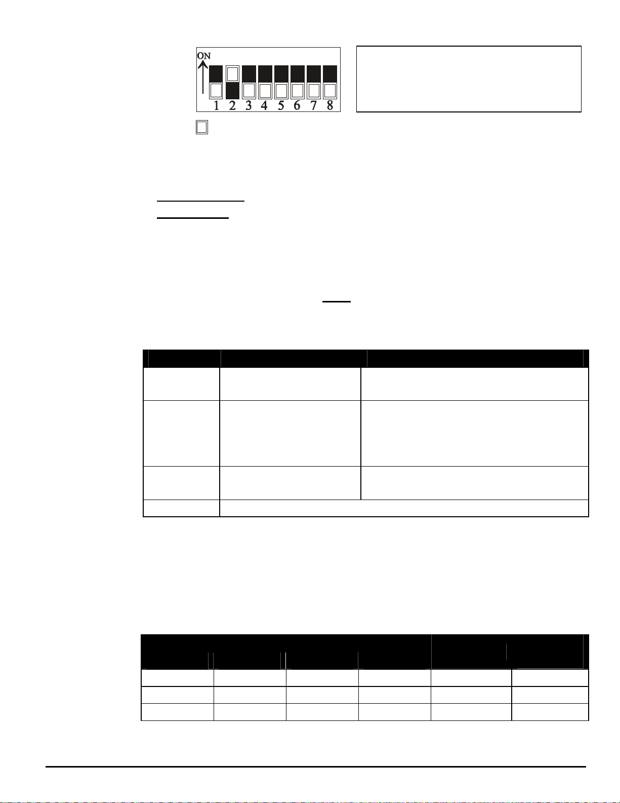
into the transport, top edge first. If the Message Preview switch is On, the
AutoLoader 500P performs a preview of the audio tape by rewinding the tape,
playing approximately 10 seconds of the audio message, stopping, waiting 5
seconds. Thiswaitprovidestheusertheopportunitytostoptapeloadbyremoving
the tape cassette from the transport. After the wait, the tape rewinds and the load
lamp flashes quickly as it awaits audio detection. As soon as audio is detected,
the load lamp becomes solid and recording begins. If the Message Preview
switch is in the Off position, the unit will skip the preview, going directly into the
recording process. Once audio information is detected, the Load lamp turns on,
indicatingthatthe message is loading. The AutoLoader 500P monitorstheaudio
information on the tape for a 6 second period of silence. This 6 seconds of silence
indicates the end of the audio message, recording is stopped and the last 6
seconds of silence is removed. At the end of message loading, the tape rewinds
and message play begins, indicated by a solid play lamp.
Once loaded and playing, the tape is not required unless a power failure occurs.
Removal of the tape cassette does not affect playing of the recorded message.
Insertion of acassette, however, causesthe AutoLoader 500P tostopmessages
playing and initiate message loading. It is recommended that the tape be left in
the cassette deck to facilitate automatic message re-load in the event of a
prolonged power outage.
MESSAGE PLAY OPERATI
MESSAGE PLAY OPERATIMESSAGE PLAY OPERATI
MESSAGE PLAY OPERATION
ONON
ON
The AutoLoader 500P plays the audio message on a continuous or externally
triggered mode.
Continuous Play
In Continuous Play mode (Option Select Switch #1 = OFF), once the audio
message is loaded it is played constantly, upon reaching the end of themessage,
it is immediately started again.
External Trigger
External Trigger operation (Option Select Switch #1 = ON) allows the messageto

AL-500P-II 10 12/15/1999
be activated from an external source. Electrically the trigger signal is optically
coupled providing isolation, static protection and long wiring runs (1500 feet).
Messageplayisstartedbyshortingpins1&5.Oncestarted,themessageplaysin
its entirety. At the end of the message, if pins 1 & 5 are shorted, the message
plays again.
Connector and 6' Cable Mating Connector
NTL# ECC-M5 LZR Electronics - MD50
Figure 4 – Trigger Plug Pin Numbers
TAPE PREPARATION
TAPE PREPARATIONTAPE PREPARATION
TAPE PREPARATION
Use only "Normal Bias" (Type I) tape cassettes not exceeding 90 minutes. Donot
use DOLBYor anyother type of noise reduction systems. The AutoLoader 500P
was designed for optimum results without such noise reduction techniques.
Record your productions in 2 channel mono with the audio level averaging 0dB
whilepeakingatnohotterthan+6dB.Recordings made in this formatwilloptimize
the digitizing process and provide consistent output levels on all Nel-Tech Labs
equipment.
Start the recording no further than 20 seconds from the beginning of your tape.
The message must not have levels averaging less than -25 db for longer than 5
seconds. Anypassages at less than -25 db longer than 5 seconds are interpreted
the end of the load.

AL-500P-II 11 12/15/1999
WALL MOUNT INSTRUCTI
WALL MOUNT INSTRUCTIWALL MOUNT INSTRUCTI
WALL MOUNT INSTRUCTIONS
ONSONS
ONS
Figure 5 – Wall Mount Diagram

AL-500P-II 12 12/15/1999
FCC Notice
WARNING: This equipment has been tested and found to comply with the limits for a Class A digital device pursuant to
Part 15 of FCC Rules. These limits are designed to provide reasonable protection against harmful interference when this
equipment is operated in a commercial environment. This equipment generates, uses, and can radiate radio frequency
energy and, if not installed and used in accordance with the instruction manual, may cause harmful interference to radio
communications. Operation of this equipment in a residential area is likely to cause harmful interference in which case
the user will be required to correct the interference at his/her own expense.
This digital apparatus does not exceed the Class A limits for radio noise emissions from digital apparatus set out in the
Radio Interference Regulations of the Canadian Department of Communications.
Le présent appareil numérique n'émet pas de bruits radioélectriques dépassant les limites applicables aux appareils
numériques de la Class A prescrites dans le Règlement sur le brouillage radioélectrique édicté par le ministère des
Communications du Canada.
LIMITED WARRANTY
TERMS: Nel-Tech warrants to the original purchaser ("Buyer") that the Product sold is free from
defects in material andworkmanshipat thetimeof purchase. The warrantyextends three (3)years
from the date of original purchase and covers parts and labor. Buyer must provide written notice to
Nel-Tech withinthewarrantyperiod of anydefective partorconditions. If the defect is nottheresult
of improper use, service, maintenance or installation, and if the equipment has not been otherwise
damaged or modified after shipment, Nel-Tech or its authorized representative shalleither replace
or repair the defective Product at Nel-Tech's option. No credit shall be allowed for work performed
by Buyer or unauthorized parties. Out-of-warranty repairs will be invoiced at the current Nel-Tech
hourly rate plus the cost of parts, shipping and handling. IN THE EVENT THAT THE PRODUCT
SERIAL NUMBER IS MISSING OR HAS BEEN TAMPERED WITH IN ANY WAY, THE
FOREGOING WARRANTY IS VOID AND WITHOUT EFFECT AND NEL-TECH SHALL HAVE NO
LIABILITY WHATSOEVER ON ACCOUNT OF DEFECTS TO SUCH PRODUCT.
LIMITATIONS: EXCEPT AS STATED ABOVE, THERE ARE NO WARRANTIES, EXPRESS OR
IMPLIED, THAT EXTEND BEYOND THE SPECIFICATIONS FOR THE PRODUCT. NEL-TECH
EXPRESSLYDISCLAIMSANYWARRANTY,EXPRESSORIMPLIED,THATEQUIPMENTSOLD
HEREUNDER IS OF MERCHANTIABLE QUALITY OR THAT IT CAN BE USED, OR IS FIT FOR
ANY PARTICULAR PURPOSE. BUYERPURCHASESANDACCEPTSEQUIPMENT SOLELYON
THEBASISOFTHEWARRANTYHEREINABOVEEXPRESSED. UNDERNOCIRCUMSTANCES
SHALL NEL-TECH BE LIABLE BY VIRTUE OF THIS WARRANTY OR OTHERWISE FOR ANY
SPECIAL, INDIRECT, SECONDARY OR CONSEQUENTIAL DAMAGES TO ANY PERSON OR
PROPERTY ARISING OUT OF THE USE OR INABILITY TO USE THE PRODUCT.
REPAIRING OR REPLACING PRODUCT: Buyer may obtain the repair or replacement of any
flawed part orequipment covered under this warrantythrough Nel-Tech only. Buyer isresponsible
for allshippingand handling charges in connectionwith the performance of thiswarranty. Products
returned to Nel-Tech must be securelypackaged to prevent damage intransit, freight prepaid, and
insuredforreplacementvalue. AreturnauthorizationnumberassignedbyNel-Techmustbeclearly
marked on the outside of the shipping container. Proof of purchase must accompany shipment.
Items delivered to Nel-Tech without a return authorization clearly marked on the outside of the
shipping container,and/orwithout proof of purchase willberefused. PleasecontactNel-Techatthe
address and phone number below to receive a return authorization number and to arrange for the
repairor replacementof a flawed part covered bythis warranty. PleaseindicatetheProduct'sserial
number in all correspondence; anauthorization number willnot be issued inthe absenceofaserial
number. Nel-Tech Labs, Inc., 101 Zachary Road, Manchester, NH 03109-5609, telephone (603)
641-8844.
This manual Copyright 1993-1999 byNel-Tech Labs, Inc. All rights reserved. No part of it may be
copied, photocopied, reproduced, translated, or reduced to any electronic medium or
machine-readable form without Nel-Tech's prior written consent.
Information contained herein is subject to change without prior notification. Nel-Tech Labs, Inc.
provides this manual without warranty of any kind, expressed or implied. This user's manual may
contain technical and/or typographical errors.
Printed in the U.S.A.
Table of contents