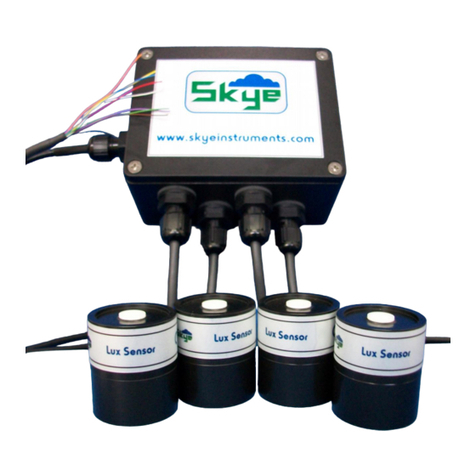
Skye SKP 220V User manual

Doc No. 485 v1a
1 Channel External Voltage Amplifier
SKP 220V
Skye Instruments Ltd.,
21 Ddole Enterprise Park,
Llandrindod Wells,
Powys LD1 6DF UK
Tel: +44 (0) 1597 824811
skyemail@skyeinstruments.com
www.skyeinstruments.com

1
Skye Instruments Ltd.
Skye Instruments is based in the UK and we are very proud to be celebrating being in business since 1983.
Our products are designed and built in the UK. We have a very wide product base and our sensors &
systems are used for plant & crop research; micro-climate, global climate change studies; environmental
monitoring and controlled environment installations.
Products include light sensors & systems, weather monitoring sensors, automatic weather stations, plant
research systems, soil and water research systems.
Feel free to contact us via our e-mail, or any of the methods below. Please click on the icons to browse the
sites, or search for the usernames.
Have a Smartphone? Scan this QR code to access our website for more information about your product:
Please be aware that the information in this manual was correct at time of issue, and should be 100%
relevant to the accompanying product. We take great pride in our ever-evolving range of products, which
means that sometimes the product may change slightly due to a re-design. If you have any queries, please
do not hesitate to contact our technical team by any of the methods above.
Skye Instruments Ltd
Skye Instruments Ltd
@skyeinstrumentsltd
@SkyeInstruments
Skye Instruments Ltd
Skye Instruments Ltd

Page
1 Introduction .................................................................. . 1
2 Wiring & Power Details .................. .................................. 2
2.1 Wiring................ ..................... .................................. 2
2.2 Connecting a Sensor ................. .................................. 2
2.3 Sensor Output & Power Supply .. .................................. 3
2.4 Connecting to Terminal ............ ................................. 4
3 Housing.................. ..................... .................................. 5
4 Specifications.......... ..................... .................................. 6
5 Troubleshooting ...... ..................... .................................. 7
CONTENTS

1
1. INTRODUCTION
Thank you for purchasing a Skye Instruments External 1-Channel Voltage Amplifier. This amplifier's function is
to transform the current from one of Skye Instruments' unamplified sensors into a voltage output, scaled over
a desired range pre-determined at the time of ordering (e.g. 0 –2V, 0 –5V, etc.).
Our range of amplified sensors have the amplification built into the sensor housing, which is the ideal situation.
This is a product for those situations where this is not appropriate (for example, where there is a limitation on
sensor height) or the amplifier is retro fitted to the sensor. The cable between an unamplified sensor and an
amplifier should be as short as possible and fixed down firmly.
Please Note:
Please ensure that on replacing the lid that the wires or silica gel pack do not get trapped in the
sealing lip.

2
2. WIRING & POWER DETAILS
2.1 Wiring
The wires should be connected to the terminal blocks in the following way:
Terminal No. Function Wire Colour
1 Sensor -ve current output Blue
2 Sensor +ve current output Green
3 Power supply +ve Red
4 Amplified voltage output -ve Green
5 Amplified voltage output +ve Yellow
6 Power supply ground Blue
7 Cable and amplifier screens White & Grey*
* White wire from power/output cable, Grey wire from light sensor cable
2.2 Connecting a Sensor
To retrofit a non-amplified single channel sensor, you
will need feed the cable into the External Amplifier and
connect the cable to the terminal block.
Firstly, feed the sensor cable through the cable gland
and when in place, finger tighten securely. Be sure
there is enough cable inside the box to reach the
corresponding terminals. The blue wire from the sensor
must be connected to terminal 1 and the green wire
from the sensor must be connected to terminal 2. Next
you will need to connect the grey wire from the sensor
to the white wire found loose inside the External
Amplifier. Now feed these two connected white and
grey wires into terminal 7 of the terminal block and
ensure all are tightened securely. The red sensor wire
is not connected, the end can be taped over and then
tucked under the metal plate. Finally, once the wires are
successfully connected to the terminal block, remove
the silica packet from the plastic bag and place inside
the box before screwing the lid securely in place.

3
2.3 Sensor Output & Power Supply
The following table shows the typical outputs of Skye amplifiers, along with the power supply required for
each.
Sensor Output: Power Supply Required:
Up to 0–2 V 5-15 V DC
Up to 0–5 V 9-15 V DC
Up to 0–10 V 12-15 V DC
The amplifier’s level of amplification (gain) was set at the time of manufacture and is not user adjustable.
Typical working ranges for various sensors are given below.
Sensor type: Working range: Typical Value on a Summer's Day:
PAR Special 0 –3,000 µmol m-2 s-1 >2,000 µmol m-2 s-1
PAR Quantum 0 –3,000 µmol m-2 s-1 >2,000 µmol m-2 s-1
Lux 0 –150,000 Lux >100,000 Lux
PAR Energy 0 –600 W m-2 >500 W m-2
Pyranometer 0- 1,500 W m-2 >1,100 W m-2
If the sensor is completely deprived of any light, the amplifier may still output a very small voltage (fraction
of a mV). This value is constant and can be offset. It is recorded on the calibration certificate of each amplifier.
Please Note:
Do not apply power to output lead. Output will drive loads with impedance from ∞ to about
1kW. No damage will be cause by momentary shorting to the common, but should never (even
momentarily) be shorted to the supply.

4
2.4 Connecting to the Terminal
Please also ensure that on replacing the lid that the wires or silica gel pack do not get trapped
in the sealing lip.
Connecting wire ends to the terminal is intended to be easy. Above each terminal block there is an opening
and a metal clip inside. Use a small flat-bladed screwdriver (supplied) to press down firmly on the metal clip
and insert the exposed wire into the terminal access located on the side of the terminal block. Once satisfied
that the wire is inserted deep enough, release the pressure, and the wire will be firmly secured in the terminal.
Please see the figures below. Using this system ensures that all wires have a constant pressure exerted on
them, maintaining a good connection.

5
3. HOUSING
The enclosure is made from light grey ABS (UV stabilised). Two grey nylon cable glands are fitted for cable
entry. It is considered to be protected from ingress to IP65. On no account should it be subjected to immersion.
Dimensions of the amplifier unit are approx.: 80mm x 58mm x 121mm (DxHxW), this includes the cable glands
and feet.
Please ensure that all cable glands are tightened finger tight onto each cable. This provides protection from
ingress, and provides cable retention/fastening.

6
4. SPECIFICATIONS
PAR Quantum
PAR Special
PAR Energy
Pyranometer
Lux
Working Range (1)
0-3000
µmol m-2 s-1
0-600
W m-2
0-1500
W m-2
0-150
klx
Sensor Passband
PAR
400 - 700 nm
350 - 1100 nm
CIE photopic
Curve V(λ)
Housing
IP65
Enclosure: Light Grey ABS, PC (UV stabilised)
Cable Glands: 2* Grey Nylon
Dimensions
80mm x 58mm x 121mm (DxHxW)
including cable glands and feet
Weight
300g (with 3m cable)
Cable
7-1-4C military specification
Voltage Output
Customer choice of 0-1V up to 0-10V
Linearity error over
working range
<0.2%
Absolute calibration
error
Typically 3%, but <5%
Temperature
Co-efficient
± 0.1%/°C
Long term stability
(2)
± 2%
Response Time (3)
<10ms
Operating Range
-20°C to +70° C
0-100% RH
Power Supply
Requirements
Minimum power supply required = max output +2V DC, up to 15 V DC
NOTES ON SPECIFICATIONS
(1) All Skye sensors will work at levels of irradiance well above that found in terrestrial sunlight conditions,
room or growth chamber lighting. These are default working ranges, check individual calibration certificate.
(2) Maximum change in one year. Calibration check recommended at least every two years. Experience has
shown that changes are typically much less than figures quoted.
(3) Times are generally less than the figure quoted, which is in milliseconds. They may be slightly increased
if long leads are fitted, or those of a higher capacity cable.

7
5. TROUBLESHOOTING
If you have any problems with using the external amplifier unit, please refer to this section. If you still have
+44(0)1597 824 811.
My sensors are not reading what I expect / I'm getting odd readings.
First of all, ensure that the sensors are level, and facing the source of light/area that it should be measuring.
This sounds very simple, but this can be an easily overlooked when encountering problems!
Also, check that the correct wires are connected to the correct terminals.
Another reason that may account for this is inadequate power supply. If your output range is between 0 and
up to 3V, the power supply should be between 5 and 15V. If your output range is between 0 and 3 to 6V, the
amplifier will require a power supply of between 9 and 15V.
The readings I'm getting are noisy.
At all times, the cable must be securely fastened down.
Also, ensure that the screening is maintained throughout between the sensors and the amplifier. The sensor
cable has an overall cable screen connected to the grey wire.

Skye Instruments Ltd.,
21 Ddole Enterprise Park,
Llandrindod Wells,
Powys LD1 6DF UK
Tel: +44 (0) 1597 824811
skyemail@skyeinstruments.com
www.skyeinstruments.com
Table of contents
Other Skye Amplifier manuals
