Norma REVO HS-DA1 Series User manual
N O R M A
N O R M AN O R M A
N O R M A
A U D I O E L E C T R O N I C S
R E V O H S - D A C
R E V O H S - D A C R E V O H S - D A C
R E V O H S - D A C S a f e t y & U s e r
S a f e t y & U s e r S a f e t y & U s e r
S a f e t y & U s e r M
MM
M
A N U A L
A N U A LA N U A L
A N U A L
p a g
p a g p a g
p a g .
1
11
1
A U D I O E L E C T R O N I C S
HS-DA1 Series
S
AFETY
M
ANUAL
U
SER
M
ANUAL

N O R M A
N O R M AN O R M A
N O R M A
A U D I O E L E C T R O N I C S
R E V O H S - D A C
R E V O H S - D A C R E V O H S - D A C
R E V O H S - D A C S a f e t y & U s e r
S a f e t y & U s e r S a f e t y & U s e r
S a f e t y & U s e r M
MM
M
A N U A L
A N U A LA N U A L
A N U A L
p a g
p a g p a g
p a g .
2
22
2

N O R M A
N O R M AN O R M A
N O R M A
A U D I O E L E C T R O N I C S
R E V O H S - D A C
R E V O H S - D A C R E V O H S - D A C
R E V O H S - D A C S a f e t y & U s e r
S a f e t y & U s e r S a f e t y & U s e r
S a f e t y & U s e r M
MM
M
A N U A L
A N U A LA N U A L
A N U A L
p a g
p a g p a g
p a g .
3
33
3
INDEX
SAFETY MANUAL
1 PRELIMINARY INDICATIONS
2 PACKING & UNPCKINGA
3 TRANSPORT AND POSITIONING
4 CONNECTIONS
5 MAINTENANCE AND SUPPORT
6 USAGE
7 REMOTE CONTROL
8 GENERAL
9 RECYCLING,
10 LIMITATION o USE in USA-CANADA-MEXICO
USER MANUAL
1 CONTROLS AND CONNECTIONS
2 USE

N O R M A
N O R M AN O R M A
N O R M A
A U D I O E L E C T R O N I C S
R E V O H S - D A C
R E V O H S - D A C R E V O H S - D A C
R E V O H S - D A C S a f e t y & U s e r
S a f e t y & U s e r S a f e t y & U s e r
S a f e t y & U s e r M
MM
M
A N U A L
A N U A LA N U A L
A N U A L
p a g
p a g p a g
p a g .
Safety Manual
1 - RELIMINARY INDICATIONS
Read this manual care ully be ore removing the unit rom its packaging. Anyone considering it super luous,
ignoring what said be ore assumes all responsibility or any accidents or incidents derived rom improper use.
The manual explains the main sa ety rules that must be ollowed care ully: Failure to comply may result in
serious injury, as with any device or appliance powered by the mains voltage. They also learn how to use or
optimal per ormance and diversi ied products, and these, although machines or playing recorded music,
are designed to protect the user rom hazards arising rom the presence o voltage. Must be care ul not to
touch live electrical parts wearers o cardiac devices electrically powered [peace maker] or therapeutic
devices or electric or electronic. The electrical sa ety is due to its connection to sa ety ground. Be ore
connection and use so make sure that the system grounding is e icient and the corresponding regulations.
NORMA is not responsible or any damage resulting rom wrong system grounding or ine icient directives
and regulations. Also check that the mains voltage is the same as that which must be ed the equipment.
2 – ACKING & UN ACKING
Remove the machine rom its packaging and place it in a horizontal position, resting on the lower legs. Play
attention to the material and packaging bags, should be stored in a dry place away rom ire hazards,
given the nature o the materials they are made o . Should not be accessible to children to avoid the
danger o su ocation.
3 - TRANS ORT AND OSITIONING
Move and transport it care ully, taking care to maintain a irm and sa e grip, do not place or carry it to
heights that can become dangerous in the event o a all.
Place it on solid supports and sur aces, out o the reach o children.
The electronics must operate in a dry place sheltered rom the weather o any kind. Do not expose the
electronics to any type o moisture, rain, vapour, spray mixtures. Keep the device away rom sources o
electric ields, magnetic and electromagnetic ields. Never place in devices one above the other; they must
operate in a horizontal position in order to better dissipate the heat produced, but should never be
overlapped. The equipment must be installed away rom sources o heat and direct sunlight, so as to allow
good air circulation.
3.1 TEM ERATURE
The device is designed to operate in normal domestic environments at a temperature ranging between 10
and 30 degrees centigrade. During operation o the ampli ier, and or a time consistently long a ter it is
turned o , the heat sink can reach high temperatures and there ore dangerous to touch. Never touch the
heat sink during operation and or at least one hour a ter shutdown.
4 - CONNECTIONS
Be sure to read the writing ound on covers and rear panels, study the layout and get a eel or subsequent
connections.
Connect inputs and outputs always with power turned o .
Allow at least 10 minutes a ter turning o the unit and not operate until the lights internal and / or external
prove still lit, even weakly. Be care ul not to short or connect any o the terminals, you can damage
speakers and electronics. The last connection be ore use continues to be the power supply.
Connect inputs and outputs always with power turned o . Allow at least 10 minutes a ter turning o the unit
and not operate until the lights internal and / or external prove still lit, even weakly. Be care ul not to short
circuiting or connect any o the terminals, you can damage speakers and electronics. The last connection
be ore use continues to be the power supply.

N O R M A
N O R M AN O R M A
N O R M A
A U D I O E L E C T R O N I C S
R E V O H S - D A C
R E V O H S - D A C R E V O H S - D A C
R E V O H S - D A C S a f e t y & U s e r
S a f e t y & U s e r S a f e t y & U s e r
S a f e t y & U s e r M
MM
M
A N U A L
A N U A LA N U A L
A N U A L
p a g
p a g p a g
p a g .
5
55
5
5 - MAINTENANCE AND SU ORT
The equipment must be checked by quali ied personnel when:
- The power cord, the plug or the socket appear to be damaged;
- Objects, liquids or mixtures o any kind has been spilled into the appliance;
- The unit does not operate properly;
- The device has been dropped or damaged;
- The device emits an unusual odour or smoke;
Do not open or remove the cover under any circumstances. Not personally intervene to replace the uses.
The operation, even in its own intrinsic banality, involves extremes caution and requires specialised
personnel who are amiliar with electrical equipment and the ability to investigate the cause o the ault.
For any operation always contact a service center authorised by the manu acturer and that has original
spare parts. The inner tunnel must not be removed by anyone and or any reason: it is essential or the
isolation rom the mains voltage. For any problem that assistance deemed to come rom an element in
series with the mains voltage, the device must be sent to the manu acturer. The electronics must not be
altered or tampered with. In act, despite the measures designed to protect the user, it is impossible to
predict any misuse o the equipment. Means or misuse any action contrary to the above issues or needs o
tool that disassemble, unscrew and remove mechanical and electrical parts o the product.
Failure to use original spare parts makes the device does not meet the design speci ication.
6 - USAGE
Avoid touching either directly or through objects and tools inside the case until it is connected to the
network: this action, as well as causing damage to the user because exposed to dangerous voltage may
damage the electronics.
- Do not remove the top cover or any reason, which is essential or the isolation rom the high voltage inside.
During operation and as long as the equipment is connected to the mains or any reason do not touch the
metal part o the electrical connection terminals: at their ends may be present high voltages.
For cleaning do not use any type o solvent hate volatile substance, alcohol, spray or lammable. Never
clean the appliance during operation. For cleaning methods consult the owner's manual.
7 - REMOTE CONTROL
Use the remote control with the attention reserved or electronics in general, avoid exposing it to excessive
heat, humidity, magnetic ields and shocks that could a ect its unctionality. Use only alkaline batteries o
the type indicated in the remote control and insert them properly orienting the positive and negative poles.
Battery li e varies depending on usage. Once discharged, not groped to re ill them. The batteries should be
stored in appropriate containers or disposal with the least possible damage to the environment. Keep
batteries out o the reach o children and pets. Remove them rom the remote control i you will not use it or
long periods.
8 - GENERAL
Failure to comply with any o the points above will void the warranty. The manual sa ety and operating
instructions must be kept with the packaging and always accompany the appliance or moving or shipping.
For any problem o any kind please contact the manu acturer directly. Anyone who ails to comply with the
above particulars makes devices have been ine ective, the consequences o such actions in violation o
the rules o sa ety and will only be attributed to the irresponsible super iciality users. NORMA is not responsible
or any errors, omissions or incompleteness o this manual, as it is not responsible or accidents or damages o
any kind that may result rom non-compliance, even partial, o the in ormation provided in this manual.
Despite the e ort to identi y all possible situations o danger, is not responsible or any damage that may be
caused to people or things rom improper use o the appliance or done against common sense.

N O R M A
N O R M AN O R M A
N O R M A
A U D I O E L E C T R O N I C S
R E V O H S - D A C
R E V O H S - D A C R E V O H S - D A C
R E V O H S - D A C S a f e t y & U s e r
S a f e t y & U s e r S a f e t y & U s e r
S a f e t y & U s e r M
MM
M
A N U A L
A N U A LA N U A L
A N U A L
p a g
p a g p a g
p a g .
6
66
6
9 - RECYCLING
Caring or the Environment by Recycling
Legislative Decree 25 July 2005, 151
Implementation o Directives 2002/95/EC, 2002/96/EC and 2003/108/EC on the reduction o use o
hazardous substances in electrical and electronic equipment and the disposal o waste
This product is marked with the recycling regarding the disposal o electrical and electronic equipment. This
means that this product must be taken to a recycling center in accordance with Directive 2002/96/EC, so
that they can be recycled or dismantled so as to minimise the impact on the environment. Do not dispose
o this product as household waste. I no suitable collection systems, please contact the authorised service
center nearest you, your dealer or, in the case o Italy, please contact the manu acturer directly.
For more in ormation on this you may want to contact your local or regional.
10 - LIMITATION of USE in USA-CANADA-MEXICO
The use o any NORMA AUDIO, OPAL ELECTRONICS product in USA, CANADA, MEXICO is authorized ONLY i
the product has been imported and sold by NORMA’s o icial distributor, as indicated on NORMA AUDIO
website (www.normaudio.com).
I the product is not sold by NORMA’s o icial distributor, in addition to the ollowing documents:
- Sa ety Manual, User's Manual, warranty, conditions o service and repair - OPAL ELECTRONICS NORMA
makes
ABSOLUTE PROHIBITION OF USE o any o its products in the ollowing countries:
UNITED STATES OF AMERICA, CANADA, MEXICO
As stated in the SECURITY MANUAL, in the USER MANUAL, and in the WARRANTY DOCUMENT, OPAL
ELECTRONICS and NORMA AUDIO strictly orbid the use o any kind o NORMA products in the ollowing
countries: USA, CANADA, MEXICO.
In These country is strictly orbidden:
- To import (directly or agency)
- To sell
- To use (including occasional use or or short periods o time)
any kind o NORMA AUDIO product, unless the unit has been imported and sold by NORMA’s o icial
distributor.
There ore, OPAL ELECTRONICS and NORMA AUDIO can not be held responsible or any loss or damage,
both direct or indirect, caused by unauthorised use o their products in the above mentioned countries.

N O R M A
N O R M AN O R M A
N O R M A
A U D I O E L E C T R O N I C S
R E V O H S - D A C
R E V O H S - D A C R E V O H S - D A C
R E V O H S - D A C S a f e t y & U s e r
S a f e t y & U s e r S a f e t y & U s e r
S a f e t y & U s e r M
MM
M
A N U A L
A N U A LA N U A L
A N U A L
p a g
p a g p a g
p a g .
7
77
7
User Manual
Congratulations!
The product you have purchased and you are going to use is the result o a long process o research and
development, to bring you the best that current technology allows us to express in electronic intended or
audio playback, both in terms o construction quality that listening quality.
We are con ident that you will ind great satis action rom the use o our products, which, i treated with
care, will reciprocate with a durable reliable. However, prior to use, is indispensable to read and transpose
the brie notes attached below.

N O R M A
N O R M AN O R M A
N O R M A
A U D I O E L E C T R O N I C S
R E V O H S - D A C
R E V O H S - D A C R E V O H S - D A C
R E V O H S - D A C S a f e t y & U s e r
S a f e t y & U s e r S a f e t y & U s e r
S a f e t y & U s e r M
MM
M
A N U A L
A N U A LA N U A L
A N U A L
p a g
p a g p a g
p a g .
8
88
8
1 – CONTROLS AND CONNECTIONS
Re er to the attached drawing in the last pages o the manual
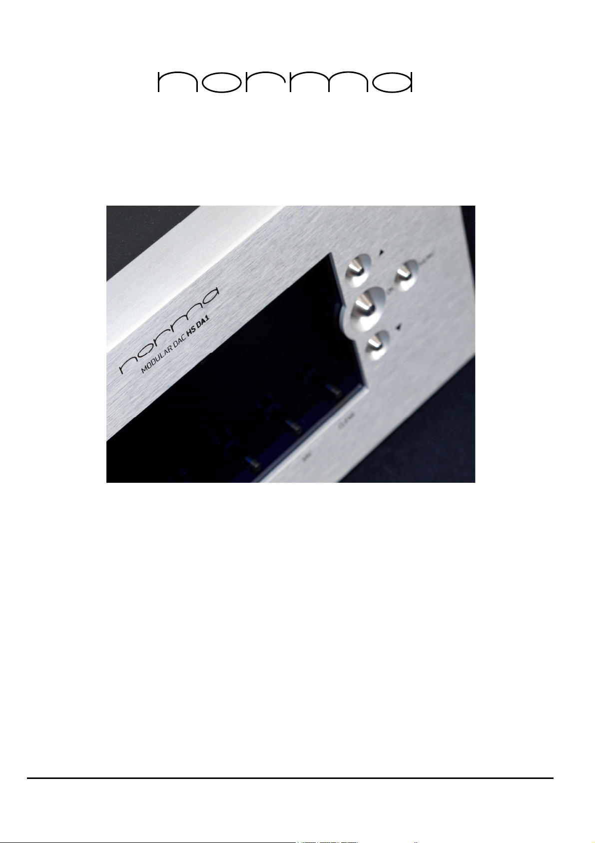
1.1 – Front anel
1 - Multi-function display
The display show the controls and unctional states.
2 - Indicator OWER STAND-BY
In the state o STAND-BY indicator is illuminated.
In the state o POWER ON indicator is o .
3 - MENU button
Enables and disables access to the setup unctions o the operating parameters.
4 - Command CLEAR
Delete the data or selection.
5 - OK button
Con irms the data or the unction active at that moment.
6 - Button ▲
▲▲
▲ [SEL-] [VOL-]
selection button BACK [-].
button to decrease volume [VOL-].
7 – Button ▼
▼▼
▼ [SEL +] [VOL +]
NEXT selection button [+].
button to increase the volume [VOL +].
8 – HEAD (works only in HS-DA1 PRE version)
Disables outputs and activates headphone output. A light turns on to signal the use o the headphone.
9 – ANALOG (works only in HS-DA1 PRE version)
Switches between analog inputs.
10 - DIGITAL
Switches between digital inputs.
11 - SRC
Toggles oversampling. I a speci ied value has been set in the setting menu, it applies that value, otherwise it
goes in AUTO mode.

N O R M A
N O R M AN O R M A
N O R M A
A U D I O E L E C T R O N I C S
R E V O H S - D A C
R E V O H S - D A C R E V O H S - D A C
R E V O H S - D A C S a f e t y & U s e r
S a f e t y & U s e r S a f e t y & U s e r
S a f e t y & U s e r M
MM
M
A N U A L
A N U A LA N U A L
A N U A L
p a g
p a g p a g
p a g .
9
99
9
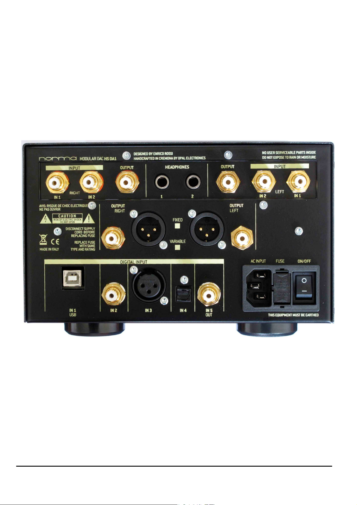
1.2 - List of Controls and Rear Connections
A - ON / OFF switch.
B - Mains socket
Mains power connector. Slot or connection o the network cable according to IEC / CEE 22. Check that the
mains voltage corresponds to that indicated on the label on the rear panel.
C - Fuse
The AC power use. Veri y that the voltage, the type and extent coincides with that indicated on the rear
panel. Attention!! For any reason the user must replace the use, it is a task reserved or quali ied personnel in
the service centers.
D - IN 1: plug RCA connection sockets (HS-DA1 RE only)
Analog Input socket or signal IN 1 channel right / le t.
E - IN 2: RCA sockets connection plug (HS-DA1 RE only)
Analog Input socket or signal IN 2 channel right / le t.
F - OUT 1 Unbal. RE: lug RCA connection sockets (HS-DA1 RE only)
OUTPUT ANALOG PRE, signal output socket [UNBALANCED] channel right / le t.
(Level variable by volume control)
G - OUT 2 Unbal. : lug RCA connection sockets
OUTPUT ANALOG signal output socket [UNBALANCED] channel right / le t.
(Level variable by volume control only on VAR version)
H - OUT 2 Bal. : Balanced XLR sockets connection
OUTPUT ANALOG signal output socket [BALANCED] channel right / le t.
(Level variable by volume control only on VAR version)
I - Digital IN 1 : USB “B style” plug connections socket
Input socket or digital signal input 1.
L - Digital IN 2 : S/ DIF RCA plug connection socket
Input socket or digital signal input 2.
M - Digital IN 3 : AES/EBU XLR plug connection socket
Input socket or digital signal input 3.
N - Digital IN 4 : S/ DIF TOSLINK plug connection socket
Input socket or digital signal input 4.
O - Digital IN 5 : S/ DIF RCA plug connection socket
Input socket or digital signal input 5.
1.3.1 – Note on the Inputs
The output 2 can be used as a balanced output when connected with XRL. To achieve the balanced signal
rom the unbalanced source coming rom the HS-DA1. It ollows that the per ormance (and instrumental
sound) o the preampli ier can be in luenced by the presence o this additional component. We
recommend, where possible, to make some listening tests between the RCA & XLR in order to establish, in
the particular con iguration o the user, what type o connection is to be pre erred.
In carrying out comparative tests must be taken o a number o important actors o in luence, including:
- The ampli ier to be connected, in the majority o cases, have di erent circuit con igurations in their inputs
RCA or XLR. It is not always true that the XLR connection is the best ever, and o ten the topology o the
source and/or o the ampli ier is unbalanced, then the XLR is obtained using a Additional circuitry, (however
sometimes is also true the exact opposite) .
In this case, the use o XLR connection source / ampli ier involves un avorable presence o 2 additional
stages in the signal path.
- XLR interconnect cables are o ten o a di erent quality rom the RCA cable. This actor must be taken into
account in the analysis o its ratings.

N O R M A
N O R M AN O R M A
N O R M A
A U D I O E L E C T R O N I C S
R E V O H S - D A C
R E V O H S - D A C R E V O H S - D A C
R E V O H S - D A C S a f e t y & U s e r
S a f e t y & U s e r S a f e t y & U s e r
S a f e t y & U s e r M
MM
M
A N U A L
A N U A LA N U A L
A N U A L
p a g
p a g p a g
p a g .
1 0
1 01 0
1 0
1.3.2 – Note on the Connections
The device must be able to make the most o their eatures. Nothing in the listening chain should not be
overlooked, starting with the interconnect cables, which must be o excellent quality, very transparent and
neutral.
The NORMA products are o extremely high quality and should be given them the opportunity to develop
the best per ormance.
Nothing in the listening chain should be underestimated, rom the quality o the cables to the position o the
speakers.
For example, i cables used are o low quality the resulting sound will be much less than the potential o the
device.
1.4 – The Warm Up and Run In
The warm up is a undamental actor. For the best sound per ormance, we recommend an initial run o
about 200 to 300 hours o operation with active speakers connected and music played at a normal listening
level. A ter a long period o inactivity, it is recommended to restore the run in. Similarly, to obtain the best
sound we recommend to warm up the product or at least 3 - 4 hours.
1.5 – The roblem of Hum
Frequently the connection o multiple devices can cause a certain amount o humming, even when the
individual devices are entirely silent. Connecting together the equipment can create ground loops, that or
induction introduce in the audio signal a certain amount o network harmonics. This problem, which also
a ects the pro essional installations more sophisticated, is long-standing and not easy to solve; its in luence is
particularly evident in the case o high gain ampli iers and in the presence o signals o very low amplitude.
The situation may sometimes be particularly critical with regard to the phono stages, turntables and
cartridges.
We point out some possible remedies:
- Reduce the length o the connection cables;
- Change position o signal cables and power network;
- Increase the distance or arrange them in a di erent way;
- Avoid using devices that can induce electromagnetic ields or inter erence, such as electric motors,
luorescent lights or lamps or low voltage trans ormers;
- It may be use ul to raise the shields o the mass signal connection rom one side o their termination. I a
device proves involved in hum problems and / or ground loops is made precise prohibition disconnect the
ground o electrical sa ety, contact the manu acturer instead to try to solve the problem.
- The electrical sa ety is due to its connection to sa ety ground. Be ore connecting and use the device,
make sure that the grounding system is e icient. . NORMA is not responsible or any damage resulting rom
wrong system grounding or ine icient directives and regulations or a disconnection in any way made,
ground security equipment.
- Check that the power cable network has the ground connection and do not remove it or any reason.
- The new LED TV or PLASMA TV emit large amounts o in rared rays that can inter ere with the IR remote
control signal.

N O R M A
N O R M AN O R M A
N O R M A
A U D I O E L E C T R O N I C S
R E V O H S - D A C
R E V O H S - D A C R E V O H S - D A C
R E V O H S - D A C S a f e t y & U s e r
S a f e t y & U s e r S a f e t y & U s e r
S a f e t y & U s e r M
MM
M
A N U A L
A N U A LA N U A L
A N U A L
p a g
p a g p a g
p a g .
1 1
1 11 1
1 1
2 – USE
2.1 – Norma IR Remote Description
The IR remote can access all operating unctions. For a complete description, see the appropriate section
o the manual.
2.2 – Turn ON/OFF
The REVO series is equipped with a sophisticated power on system, integrated with the system remote
control and electronic protections. This system consists o three phases: POWER OFF, STAND-BY, POWER ON
[OPERATE].
2.2.1 OWER OFF: In this phase, the rear control switch is in the OFF position and the ampli ier is o .
2.2.2 STAND-BY: placing the rear control switch in the ON position, the ampli ier is active in STAND-BY POWER
indicator on the ront panel will lights up at low intensity. This condition can be maintained inde initely, the
ampli ication stages are not powered, but the ampli ier is ready to receive the command switch.
2.2.3 OWER ON [O ERATE]: the power is on to all intents and purposes, this can be determined by the
action on the ront POWER button or IR remote POWER button.
2.2.4 STAND-BY: to bring the unit in STAND-BY, press the POWER button [or the POWER button on the remote
control].
2.2.5 OWER OFF: to bring the ampli ier in POWER OFF condition, a ter having acted on the POWER
command, put the rear control switch in OFF position. Never work directly on the rear control without irst
place the unit in STANDBY.
2.3 – Functional Settings, Set Command
With the MENU (SET on RC) button you can set various unctional parameters, as described in the ollowing
paragraphs. In conjunction with the SEL +, SEL -, OK.
It 's possible to access many settings "nested" within the MENU unction. Once you press MENU you can
access the ollowing con iguration menus using the SEL +, SEL- buttons
1 System Settings
2 Analog Settings (only in HS-DA1 PRE version)
3 Digital Settings

N O R M A
N O R M AN O R M A
N O R M A
A U D I O E L E C T R O N I C S
R E V O H S - D A C
R E V O H S - D A C R E V O H S - D A C
R E V O H S - D A C S a f e t y & U s e r
S a f e t y & U s e r S a f e t y & U s e r
S a f e t y & U s e r M
MM
M
A N U A L
A N U A LA N U A L
A N U A L
p a g
p a g p a g
p a g .
1 2
1 21 2
1 2
2.3.1 – System Settings
This section lets you customize all the characteristics o your device. You will ind the submenus RESUME,
LIGHT, DISPLAY and OUT (HS-DA1 VAR only)
RESUME
Stores the current settings and makes it de ault.
LIGHT
Adjusts display brightness between values 30, 50. 70, 100.
DISPLAY
When ON, enables display to turn o automatically a ter a ew seconds without commands.
OUT (only in HS-DA1 VAR version)
Lets you switch between direct and variable output mode. When in direct, the sound is sent directly to the
output, when in variable it passes through the potentiometer, and lets you adjust the volume with the
remote or with the arrows on the ront panel o the device.
2.3.2 – Analog Settings (only in HS-DA1 RE version)
This sections lets you set the gain and volume levels or every set o inputs (digital, analog 1 and analog 2)
In everyone o these section you will ind two submenus, LINE and HEAD.
LINE:
GAIN: can be set to HIGH, LOW or PASSIVE
GAIN LINE DEFAULT value :
VOLUME: can be set between -5 and -45, or in OFF position
HEAD:
GAIN: can be set to HIGH or LOW
GAIN HEAD DEFAULT value :
VOLUME: can be set between -5 and -45, or in OFF position
It’s important to remember that the GAIN preset values can be manually changed by dedicated jumpers
on the board. Three (3) di erent values are available or the HIGH setting, while 2 are available or the LOW
setting, both in line and headphone mode.
The procedure to change preset gain values will be explained urther on in this manual.
See 2.6 – Manual Gain Setting (Jumpers) (HS-DA1 Pre version only)
The VOLUME option sets a re erence value or the input, to easily handle sources with di erent output levels
without constantly adjusting the volume manually. In OFF mode it doesn’t manage the volume storing.
The PASSIVE setting or the GAIN skips the gain stage and connects directly to the volume stage.
The PASSIVE is not available or HEADPHONES output.
2.3.3 – Digital Settings
The number shown in the submenu is the one o which you want change settings, by de ault you will see the
input currently in use, pressing SEL+ \ SEL- select the desired input.
Note that you can still change the con iguration o any input without interrupting playback o the current
one. (For Example: while listening IN2 you can change the settings or INPUT 5).
Press OK to enter the submenu.
Now you can cycle through the ollowing con igurations using SEL+ \ SEL- buttons.

N O R M A
N O R M AN O R M A
N O R M A
A U D I O E L E C T R O N I C S
R E V O H S - D A C
R E V O H S - D A C R E V O H S - D A C
R E V O H S - D A C S a f e t y & U s e r
S a f e t y & U s e r S a f e t y & U s e r
S a f e t y & U s e r M
MM
M
A N U A L
A N U A LA N U A L
A N U A L
p a g
p a g p a g
p a g .
1 3
1 31 3
1 3
2.3.3.1 – DAC Input Configuration : arameters
Message Function Possible choice Note
FSrC UpSampler OFF - 44.1 - 88.2 - 176.4 - 48.0 - 96.0 - 192.0 KHz, AUTO
CLSr Clock Source In / Local
drdn Direct Down OFF / ON
Fdig Digital Filter SLOW / SHAR
FANA Analog Filter 0 /1 Not applicable in this unit
dEEn De-Emphasis Control OFF/ON/AUTO
POLA DAC Polarity 0/180
dEFA De ault Parameters NO/ON
2.3.3.2 – Upsampling Frequency Setting
I you want to select the requency value o UpSampling ollow the instruction below:
A – In SPDIF input, with CLSr - Clock Source in IN (Input) mode, will be possible to use only the x1, x2, x4 value
o input requency. I you select di erent values, the system automatically sets the requency value closest.
I you want to select other value, you can use CLSr - Clock Source in LOCAL mode.
B - In AUTO mode, the system automatically sets the requency value to 176.4 KHz or 44.1/88.2/176.4 KHz
input values or 192.0 KHz or 48.0/96.0/192.0 KHz input values.
2.3.3.3 - Clock Source Setting
When UpSampler mode is active, you can select the clock source or the D / A conversion.
In IN (Input) mode, the DAC use the clock rom the input signal.
In LOCAL mode, the DAC use the clock generated by the local oscillator.
We recommend to do some listening tests to determine what is the best solution.
The unit clock is generated by oscillators o high quality, but it may be that the clock associated with the
input signal provides superior audio per ormance.
2.3.3.4 – Direct Down SRC Setting
When Upsampler mode is active, you can select the Direct Down mode.
Re er to page 69 o SRC4392 data sheet :
“ … Decimation Filter/Direct Down-Sampling Function
This bit selects the mode of the decimation function, either true decimation filter or direct down-sampling without filtering.
Note: Direct down-sampling should only be used when the output sampling rate is higher than the input sampling rate. When the
output sampling rate is equal to or lower than the input sampling rate, the Decimation Filter must be used in order to avoid
aliasing… “
Remember, i you select the Direct Down mode and the output sampling rate is equal to or lower than the
input sampling rate, the system automatically switches in Direct Down = OFF.

N O R M A
N O R M AN O R M A
N O R M A
A U D I O E L E C T R O N I C S
R E V O H S - D A C
R E V O H S - D A C R E V O H S - D A C
R E V O H S - D A C S a f e t y & U s e r
S a f e t y & U s e r S a f e t y & U s e r
S a f e t y & U s e r M
MM
M
A N U A L
A N U A LA N U A L
A N U A L
p a g
p a g p a g
p a g .
1
11
1
2.3.3.5 - Digital Filter Setting
You can select the digital ilter in the two modes SLOW & SHARP
In SLOW mode, the response o the ilter provides the best per ormance and linearity or time response.
In SHARP mode, the response o the ilter provides the best per ormance and linearity or requency
response.
For more in ormation, please re er to the data sheet DF1706, p.4
2.3.3.6 – Analog Filter Setting
This parameter is not applicable in this unit.
2.3.3.7 – DeEmphasis Control Setting
This parameter is used to set the operation o de-emphasis.
In OFF mode the de-emphasis is always OFF.
In ON mode to de-emphasis is always ON i the input requency is 44.1 KHz or 48.0 KHz.
In AUTO mode, the de-emphasis is enabled automatically by the system when it detects the presence in the
SPDIF signal.
The de-emphasis is indicated by a “E” FLAG in the display. When it lashes, the de-emphasis is detected in
the input signal but NOT activated. When lit, the de-emphasis is active.
NOTE: The procedure or emphasis / de-emphasis is not very common and has been used mainly in CD’s
made in the 80's. However, we must consider that many burns so tware, and many recording drive or PC
does not manage in ormation relating to de-emphasis.
I a digital audio track sounds a bit too rich in high requencies, maby because the emphasis lag was lost
during the copy o the track, you can manually enable de-emphasis.
2.3.3.8 – DAC olarity Setting
This parameter is used to set the values o the output polarity.

N O R M A
N O R M AN O R M A
N O R M A
A U D I O E L E C T R O N I C S
R E V O H S - D A C
R E V O H S - D A C R E V O H S - D A C
R E V O H S - D A C S a f e t y & U s e r
S a f e t y & U s e r S a f e t y & U s e r
S a f e t y & U s e r M
MM
M
A N U A L
A N U A LA N U A L
A N U A L
p a g
p a g p a g
p a g .
1 5
1 51 5
1 5
2.3.3.9 – Default Load Setting
It is possible to automatically restore the de ault parameters.
FSrC = OFF
CLSr = In
drdn = OFF
Fdig = Slow
dEEn = OFF
2.4 – Input Selection
With the device turned on, you can select the desired input both via RC and ront panel. On the remote
control, press the IN button, then select the desired input with the SEL + and SEL – buttons, then press OK.
On the ront panel, press the ANALOG or DIGITAL buttons, select the desired input with the arrows, then
press OK.
Please remember the analog inputs are available only in the HS-DA1 PRE version.
2.5 – Display Modes
When outside the setting menu, the display can show three di erent kinds o in ormation.
1. As standard, it will show the input in use and the sampling requency o the DAC section, plus an S i
oversampling is active.
2. By pressing the OK button, it shows the input sampling requency.
3. When a volume button is pressed, it shows the attenuation value.
2.6 – Volume Control (Only in HS-DA1 VAR and RE versions)
To adjust the volume, the user has two possibilities: by using the volume control on the remote, or by using
the buttons 6 - Button ▲
▲▲
▲ [SEL-] [VOL-] and 7 – Button ▼
▼▼
▼ [SEL +] [VOL +] on the ront panel.
Every time you act on the volume control, the display shows the attenuation value.
NOTE ON VOLUME CONTROL AND DIS LAY:
In order to be more use ul to the user, the volume indication is converted in Decibels o attenuation,
between approximately 0 and -50 dB.
Anyway, because o this scale conversion process, there may be some visualization imprecisions ( or
example, the maximum volume may stop at -2/-1 dB).
The user should not be concerned by this, as the whole attenuation range o ered by the volume control
( rom 0 to around -80 dB) is e ectively used.

N O R M A
N O R M AN O R M A
N O R M A
A U D I O E L E C T R O N I C S
R E V O H S - D A C
R E V O H S - D A C R E V O H S - D A C
R E V O H S - D A C S a f e t y & U s e r
S a f e t y & U s e r S a f e t y & U s e r
S a f e t y & U s e r M
MM
M
A N U A L
A N U A LA N U A L
A N U A L
p a g
p a g p a g
p a g .
1 6
1 61 6
1 6
2.6 – Manual Gain Setting (Jumpers) (HS-DA1 re version only)
The two pictures show the gain jumpers inside the device.
You can access them by removing the top cover.
The ollowing tables show all the combinations you can achieve ad the correspondent gain values.
Low Gain Setting
Item Selector 3 Selector 4 Gain Note
A ON (1) OFF (0) +0.5 dB Same Gain o B item,
B ON (1) ON (1) +0.5 dB Suggested or Lowest Gain
C OFF (0) ON (1) +3.0 dB Default for Low Gain Setting
D OFF (0) OFF (0) +17.5/+5.0 dB Same o High Gain Setting
High Gain Setting
Item Selector 1 Selector 2 Gain Note
A OFF (0) OFF (0) +17.5 dB
B OFF (0) ON (1) +10.0 dB Default for High Gain Setting
C ON (1) OFF (0) + 6.0 dB
D ON (1) ON (1) + 5.0 dB

N O R M A
N O R M AN O R M A
N O R M A
A U D I O E L E C T R O N I C S
R E V O H S - D A C
R E V O H S - D A C R E V O H S - D A C
R E V O H S - D A C S a f e t y & U s e r
S a f e t y & U s e r S a f e t y & U s e r
S a f e t y & U s e r M
MM
M
A N U A L
A N U A LA N U A L
A N U A L
p a g
p a g p a g
p a g .
1 7
1 71 7
1 7
2.7 – Remote Control (16 buttons)
1 - ON/OFF
Turns the device on or puts it in stand-by.
2 - MUTE
Mutes the outputs. The device will not accept other commands until mutes is pressed again.
3 - VOL +/-
Adjusts the volume.
4 - SEL +/-
Navigate through menus.
5 - DSY (RC only)
Adjusts display brightness
6 - CLR
It has the same unction o the CLEAR button on the ront panel, it deletes the data or selection.
7 - SET
It has the same unction o the MENU button on the ront panel, it enables and disables access to the setup
unctions o the operating parameters.
8 - IN
Lets you select between inputs.
9 - DAC
Not active on this device.
10 - A/
Not active in this device.
11 - AM and DIG
They select which device the remote control is driving.
For HS-DA1 use DIG mode.
12 - F1/SRC
Toggles oversampling. I a speci ied value has been set in the setting menu, it applies that value, otherwise it
goes in AUTO mode.
N O R M A
N O R M AN O R M A
N O R M A
A U D I O E L E C T R O N I C S
R E V O H S - D A C
R E V O H S - D A C R E V O H S - D A C
R E V O H S - D A C S a f e t y & U s e r
S a f e t y & U s e r S a f e t y & U s e r
S a f e t y & U s e r M
MM
M
A N U A L
A N U A LA N U A L
A N U A L
p a g
p a g p a g
p a g .
1 8
1 81 8
1 8
Table of contents
Other Norma Amplifier manuals


