Skye MiniMet User manual

MiniMet Installation Manual
Iss. 2.0
™

Page
1. INTROD CTION …............................................................................ .1
2. CHOOSING A S ITABLE LOCATION …............................................... 2
2.1 Ground based Installations …......................................................................... 2
2.2 Roof Top Installations …................................................................................ 2
3. MAST ASSEMBLY …............................................................................ 4
3.1 Joining Instructions for mast supplied in more than 1 section ….......................... 4
3.2 Erection of Mast on Grass or soft Ground ….................................................... 4
3.3 Erection of Mast on a Concrete Base …............................................................ 5
3.3.1 Bottom buried in concrete …...................................................................... 5
3.3.2 Mast bolted to a concrete base …............................................................. 5
3.4 Mast Mounted on a Roof Top …..................................................................... 6
3.5 Mast mounted on a wall …............................................................................. 6
3.6.10m Retractable Mast …................................................................................. 6
4. MO NTING THE DATAHOG OR MINIMET …....................................... 11
5. RADIATION SCREENS FOR RH & AIR TEMPERAT RE …......................... 12
6. LEVELLING NITS FOR LIGHT SENSORS …......................................... 14
7. MO NTING THE WIND SENSORS …................................................... 15
7.1 Vector Wind Sensors ….................................................................................... 15
7.1.1 Single Vector Wind Sensors …..................................................................... 16
7.1.2 Vector Anemometer plus Windvane …........................................................ 16
7.2 EML Ltd Combined Wind Speed & Direction Sensor …....................................... 16
7.3 Windsonic …................................................................................................... 17
8. RAINGA GES …................................................................................ 19
8.1 EML Ltd ARG 100 …........................................................................................ 19
8.2 Rainwise Raingauge …................................................................................... 19
8.3 Mounting Raingauges on an SKM 229 Bracket …............................................ 20
9. MO NTING THE BAROMETER …........................................................ 22
10. MO NTING THE S RFACE WETNESS SENSOR …................................. 23
11. INSTALLING TEMPERAT RE PROBES …............................................... 24
11.1 Soil Temperature Probes …............................................................................. 24
11.2 Grass Temperature Probes …......................................................................... 24
11.2.1 Assembly of the Grass Temperature Radiation Screen …........................... 24
12. INSTALLING TENSIOMETERS …........................................................... 26
13. INSTALLING AN EVAPORATION PAN & GA GE …............................... 27
CONTENTS

14. MO NTING A SOLAR HOG …............................................................ 28
15. INSTALLING MAINS HOG …................................................................ 29
15.1 Standard MainsHog ….................................................................................... 29
15.2 MainsHog with Signal Boosters …................................................................... 29
16. INSTALLING THE GSM/GPRS REMOTE LINK …......................................31
16.1 GSM/GPRS Remote Link without a Solar Panel …............................................31
16.2 GSM/GPRS Remote Link with a Solar Panel ….................................................31
17 FINAL SYSTEM ASSEMBLY …................................................................33
17.1 Standard MiniMet Assembly …..........................................................................33
17.2 GSM/GPRS MiniMet Assembly …......................................................................33
18 CALIBRATION & MAINTENANCE ….........................................................35
19 ANN AL SERVICE CONTRACTS ….......................................................... 37
20 SOFTWARE …....................................................................................... 39
21 TRO BLESHOOTING …........................................................................ 42
Appendix 1 List of Tools required for installation …................................ 43
Appendix 2 Concrete Bases ….............................................................. 44
Appendix 3 Site Location …................................................................. 45
Appendix 4 Assembly of Mast Supplied in Sections …........................... 46
Appendix 5 Assembly of Pole/Wall Mounting Brackets …...................... 47
Appendix 6 Assembly of Baseplate for ARG 100 …............................... 48
Appendix 7 Mounting of GSM/GPRS Enclosure to Bracket …................. 49
Appendix 8 Mounting of GSM/GPRS Enclosure to Mast (no solar
panel) …............ 50
Appendix 9, 10 & 11 Mounting the GSM/GPRS Enclosure on the
Mast with a Solar Panel …......... 51
Appendix 12 Typical MiniMet Installation with GSM/GPRS …................ 54
Appendix 13 Typical MiniMet Installation without GSM/GPRS …........... 55
Appendix 14 Plan of a Concrete Base for a 10m Retractable Mast …...... 56

1. INTROD CTION
This manual describes the mounting of Skye sensors and dataloggers on masts, poles or walls, and suggests
suitable installation locations to enable the most accurate measurements to be taken.
Each component part of the system to be installed is described in its own chapter, some of which may not be
applicable to your system. The final assembly is described in Section 17.
A section is included on the care and maintenance of your system, please see Section 18. Skye Instruments
also offer service / maintenance / recalibrations by post worldwide. n site engineer service visits are
available directly from Skye in the UK, please contact your local Skye distributor for details of an on site
service in your own country.
1
MiniMet Installation

2. CHOOSING A S ITABLE LOCATION FOR AN A TOMATIC WEATHER
STATION
The ideal location for installing an automatic weather station would be a flat area of short kept grassland,
minimum 10m x 10m in size, fenced and surrounded by a larger flat area with no height obstructions in the
near vicinity.
Very few locations meet these ideal conditions, so the following guidelines should be used when choosing a
suitable installation site.
2.1 Ground Based Installations
The weather station mast can be fixed into a grassy surface using guylines and pegs, or can be
bolted or concreted in place for a more permanent fixture, using the guylines as steadying structures.
The area required for a concrete base can be seen in Appendix 2.
The standard mast height is 2m, although other heights, either higher or lower may be more suitable
to your own application. If there are any tall obstructions nearby, such as trees or buildings, make
sure that the mast is placed at least twice the distance away of the height of the tallest obstruction.
See Appendix 3.
Most sensors will be mounted on a central pole, but a raingauge is fixed at a distance of 3-4m from
the base of the pole. Usually the raingauge is pegged or bolted to the ground so that the
collecting rim is at a height of 50-60 cm above the ground. However, if a solid fence is to surround
the weather station in a small area, this may interfere with rain collection, and in this case the
raingauge should be raised so that its top rim should be at least as high as the top of the fence.
It is not always essential to enclose the weather station with a fence, but it is advisable in many
cases, to prevent physical interference and damage to cables laying on the ground. A minimum
area to be considered should be around 5 x 5 m.
If theft or vandalism may be a problem, a surrounding fence is advised. A large notice saying
'Danger - High Voltage' or such similar message should deter most intruders, even though there
actually is no danger at all!
2.2 Roof Top Installations
In applications where there is no suitable open space, or it is more convenient for mains power or
permanent linking to the PC, the weather station can be installed on the roof of building. The highest
point of the tallest building should be chosen if at all possible.
2
MiniMet Installation

Again, the standard mast height is 2 m, but the actual pole height should be chosen according to
the immediate surroundings and obstructions, for example other buildings, tall trees, chimneys,
exhausts etc. The same rule applies in that the mast should be placed at least twice the distance
away, of the height of the tallest obstruction. See Appendix 3.
A 3m pole can be fixed to the side of the building, such as in a TV aerial installation, so that the
lower 1 m is bolted to the wall, and the top 2m is projected above the roof top. This can be done to
the side of a flat roofed building, or at the apex of the roof as appropriate.
If there is a handrail around the roof which is sturdy enough to prevent a person falling off, this could
be used to clamp the 2m mast in place.
Alternatively, a 2m pole can be attached to the roof top itself. The exact method will depend on the
fabrication of each roof, as usually the roof surface cannot be punctured by bolts etc. Sometimes a
large metal plate is used as a mast base, which is then weighted down with concrete blocks.
Your mast pole may have been supplied in one, two or more pieces. If it is in one single piece you
may ignore Section 3.1 and proceed to Section 3.2. If your pole is in more than one piece, following
the joining instructions in Appendix 4 before proceeding.
3
MiniMet Installation

3 MAST ASSEMBLY
3.1 Joining Instructions for a Mast supplied in more than one Section
There will be three small brass bars supplied for each joint required, each with 2 drilled and tapped
holes, and fixing bolts and washers.
Fix a brass bar into each of the three holes at the end of one of the mast sections, using the bolts
and washers, so that half of each bar is protruding. See Appendix 4.
Locate the protruding brass bars into the drilled end of the second mast section and bolt together
to form a single length. See Appendix 4.
Repeat with further mast sections as necessary.
3.2 Erection of Mast on Grass or Soft Ground
Items required: pole, base plate, tent pegs, guylines with locking ring, large guy pegs, (mallet, spirit
level - not supplied).
Place the aluminium base plate in position and insert the tent pegs only far enough to stop it
moving - it may be necessary to adjust this finally.
Pass the guyline locking ring over the pole to about halfway. If the pole has been made up of two
sections, make sure the locking ring is above the joining bolts. Place the bottom of the pole over
the raised centre of the base plate.
Lay out the guylines at 120 degrees from each other, and at an angle of about 45 degrees out
from the vertical pole. Undo the shackles at the end of the guylines, so that there is enough
adjustment for tightening later. Drive the large 45 cm 'T' pegs into the ground at the end of each
guyline and attach.
Adjust the guyline tautness by locking the ring into place, driving the 'T' pegs fully into the ground at
the correct angle (90º to the guyline), and turning the shackles to tighten, keeping the mast pole as
vertical as possible. Tighten the locking nuts on the shackles once the guylines are tight.
Finally, move the mast base plate slightly into position if necessary, so that the pole is fully vertical
(use a spirit level). Drive home the tent pegs to secure.
4
MiniMet Installation

3.3 Erection of Mast on a Concrete Base
3.3.1 Bottom Section Buried in Concrete
Items required: pole, guylines with locking ring, large guy pegs, (mallet, spirit level - not
supplied, although a MiniMet Installation Toolkit is available for purchase – please enquire).
Usually a 3 m pole is supplied, the lower 1m for burying in concrete, resulting in a 2 m mast.
Firstly, at the chosen mast location, dig a hole 1 m deep and approximately 0.5 m diameter.
Place the pole in the centre of the hole - if it has been joined from 1m + 2m sections, keep
the jointed section nearest the top. Fill around the pole with fresh concrete. Leave the
concrete to fully harden.
Pass the guyline locking ring over the top of the pole to about halfway. If the pole has been
made up of two sections, make sure the locking ring is above the joining bolts.
Lay out the guylines at 120 degrees from each other, and at an angle of about 45 degrees
out from the vertical pole. Undo the shackles at the end of the guylines, so that there is
enough adjustment for tightening later. Drive the large 45 cm 'T' pegs into the ground (90 º
angle to the guylines) at the end of each guyline and attach.
Adjust the guyline tautness by locking the ring into place, driving the 'T' pegs fully into the
ground at the correct angle (90º to the guyline), and turning the shackles to tighten, making
sure the mast pole is vertical using the spirit level. Tighten the locking nuts on the shackles.
Finally check all adjustments to ensure the guylines are taut.
3.3.2 Mast Bolted to a Concrete Base
Items required: pole, base plate, guylines with locking ring, large guy pegs, (concrete bolts,
mallet, spirit level - not supplied, although a MiniMet Installation Toolkit is available for
purchase – please enquire).
Firstly prepare the concrete base according to the dimensions in Appendix 1 and leave to
fully harden. There are two options for fixing the guylines, these may be driven into grass or
soft ground around a central, small 20 cm square concrete base, or they can be bolted into
the concrete if it is the full 1.6 m square area.
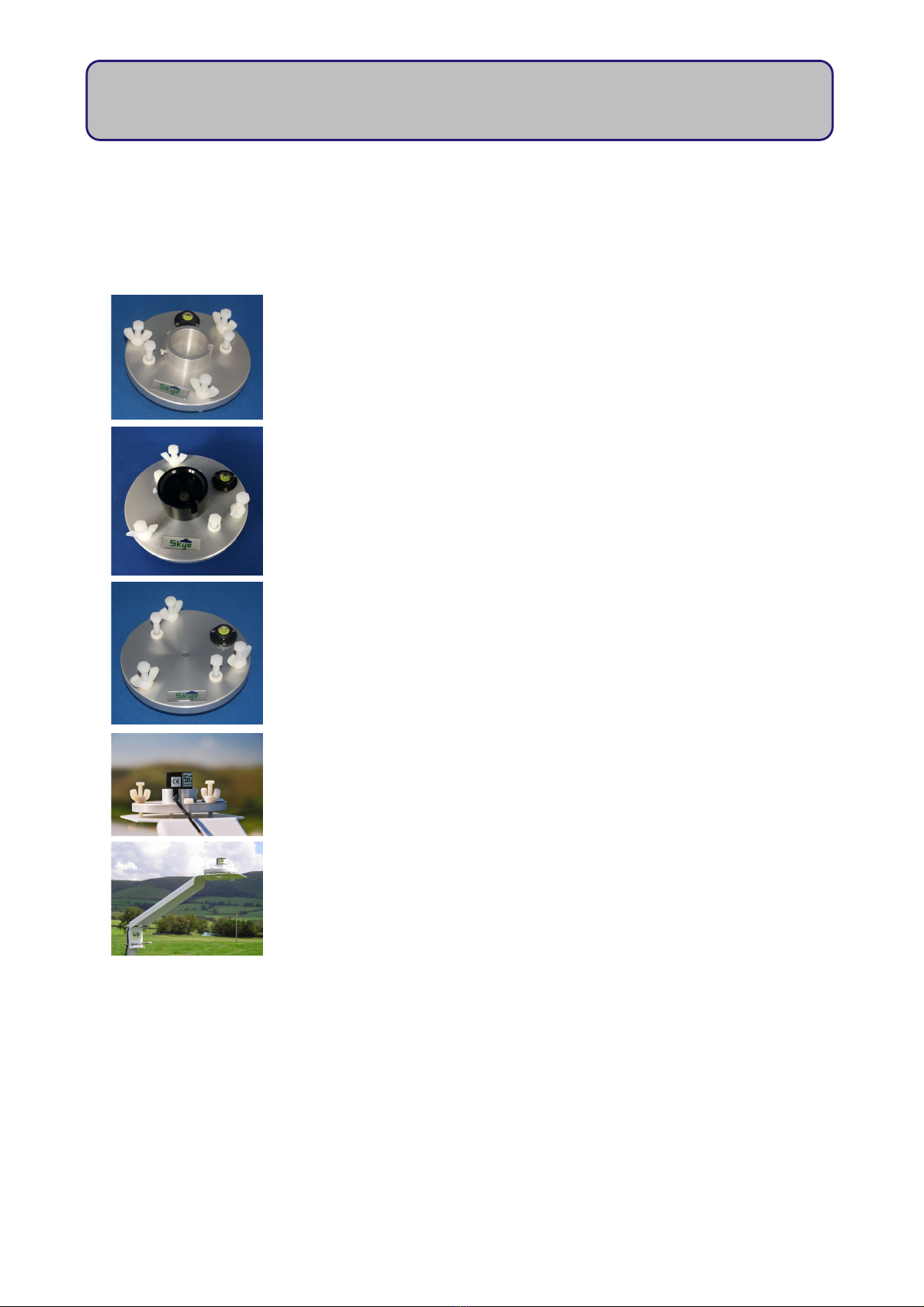
Place the aluminium base plate in position (note this isn't fully central if using a large 1.6 m
base - see Appendix 1). Drill holes for the fixing bolts and secure.
Pass the guyline locking ring over the pole to about halfway. If the pole has been made up
of two sections, make sure the locking ring is above the joining bolts. Place the bottom of the
5
MiniMet Installation

pole over the raised centre of the base plate.
Lay out the guylines at 120 degrees from each other, and at an angle of about 45 degrees
out from the vertical pole. Undo the shackles at the end of the guylines, so that there is
enough adjustment for tightening later.
If bolting the guylines to the concrete, drill holes for the fixing bolts at the end of the
guylines and attach.
If using pegs into soft ground, drive the large 45 cm 'T' pegs into the ground at the end of
each guyline and attach.
Adjust the guyline tautness by locking the ring into place, (driving the 'T' pegs fully into the
ground if appropriate), and turning the shackles to tighten, making sure the mast pole is
vertical using the spirit level.
3.4 Erection of Mast on Roof Top
As each installation will have differing circumstances, there are no
standard instructions for this section. Please contact Skye or your
local distributor for advice or an installation quotation.
3.5 Erection of Mast on a Wall
Again each installation will have differing circumstances, but Skye
can supply T&K Brackets for this type of installation.
3.6 10 Metre Retractable Mast
The mast is made up of 5 tubular aluminium sections.
The bottom tube is 2 metres long and the other four tubes are 2.2 metres long.
The diameters have been chosen so that the tubes will telescope into each other.
6
MiniMet Installation

The bottom tube is the largest diameter and does not exceed 50 mm.
The top tube is the smallest in diameter and does not exceed 38 mm.
The wall thickness of the tube is not less than 2 mm.
3.6.1 Parts List for Mast :-
1 x BASE PLATE
4 x SMALL BASE PLATE PEGS
5 x MAST SECTI NS
4 x L CKING C LLARS
4 sets x GUYLINES
3 guys per set fitted to a guyline ring, 3mm diameter galvanised steel wire
rope (min. breaking load 0.538 tonnes), with adjustable straining screws
12 x LARGE GUYLINE PEGS
1 x TEMP RARY GUYLINE SET (3 ropes and 3 small pegs)
The mast baseplate should be held in place by the small pegs if used on soft ground or
bolted in place if used on a concrete base.
The large guyline pegs are intended for use in soft ground. If the guylines are to be
anchored to a concrete base then a suitable ring or eyebolt should be fixed to the concrete
instead (please see Appendix 14)
Straining screws are attached to the lower end of the guylines. These can be hooked onto
the large guyline pegs, or it can be hooked to the ring or eyebolt if used on a concrete
base.
3.6.2 10 metre mast schematic
7
MiniMet Installation

The mast will be erected as indicated in the sketch on the previous page.
This is not a scale drawing but is intended to show how the mast would look when fully
erected.
Three guylines come from each guyline ring. The guylines from the top two rings are
anchored at points close to each other on the ground. These points should ideally be 10
metres from the base of the mast, but not less than 6 metres away. The guylines coming
from the two lower rings are anchored at points close to each other which should be 5 metres
away from the base of the mast but not less than 3 metres.
3.6.3 Erection of 10 Metre Mast
a) Pre-Installation Assembly
(Can be done before going to the installation site)
1. Lay the mast on the ground and extend the sections. You will see that the lower end of
each section has been marked with a cross hatch pattern using a permanent marker pen -
this is to show the maximum safest extension length. Extend the mast sections until the marked
areas are just not visible.
2. Gently finger tighten the guyline rings at the very top of the mast, and at 7.5m, 5m and
2.5m heights. Mark top and bottom position of the guyline ring with a permanent marker
pen (for later reference).
3. Loosen the guyline rings and compress the mast, making sure the screws on the locking
collars are approximately in line (this will aid erection later).
b) Installation On Site
(do not attempt to erect on a windy day)
1. Lay the compressed mast on the ground.
2. Fit the dual wind arm mount to the top of the pole, using the reducing adapter (usually
already fitted into the mounting).
3. Fit the wind sensors to the dual wind arm mount – note the direction of the N RTH sticker
for later positioning. (It will be useful to line up the wind arm mount with locking collar screws
when raising the sections later). Attach the rotor and vane to the wind sensors.
4. Position the mast base plate at the installation spot and secure to ground with pegs (or
bolts as appropriate).
8
MiniMet Installation

5. Drive the large guyline pegs about halfway into the (or fix bolts as appropriate), at 4.85m,
5.15m, 9.85m and 10.15m (approximately) from the mast base plate, 3 at each distance at 120
degrees circular spacing, (one for each guyline rope). Pegs should be fixed at an angle of
approximately 45 degrees pointing away from the base plate.
6. Place the compressed mast onto the base plate. Rotate so that the windvane sensor
N RTH marker is facing North, and the dual wind arm mount and locking collar screws are
facing east / west (use a magnetic compass).
7. Use the temporary rope guylines supplied to hold the compressed mast vertical (using the
small tent pegs). The temporary rope guylines are fitted by placing the small fixed loop in
each guyline rope over the hooks in the collar on the bottom section of the mast. Then with
the mast held vertical (use a spirit level) the other end of the guylines can be fixed using the
small pegs supplied. The guylines can be tightened to hold the mast firmly by pulling the
free end of the guyline. When the mast is in position tie a knot in the rope guyline's free
end to stop it slipping.
8. Begin raising the mast sections one at a time. Use a free standing ladder or platform so
that the top of the lowest section can be easily reached. This mast is intended to be
extendable to a maximum of 10 metres. Under no circumstances should the mast be
extended to a position where the cross-hatch marks on the extending sections come into view.
a) Raise the topmost section first – gradually about 0.5m at a time, use the locking
collar to temporarily hold. Secure the wind sensor cables with cable ties at each
interval.
b) Secure the guyline ring in the position marked in Pre-installation Assembly. Uncoil
the wire guyline ropes so they are accessible from the ground later.
c) Continue raising until the cross hatch pattern is reached, and then lower slightly so
that it is no longer visible. Rotate the mast section so that the protruding wind arm
mount is still in line with the locking collar screws.
d) Finally tighten the locking collar.
e) Repeat with each next section in turn, from top to bottom. If it is windy during the
installation, get some helpers to hold the longest guy ropes to prevent excessive
movement of the topmost sections in the wind until secured.
9. Begin to secure the permanent guylines set by set, starting from the lowest (shortest) set.
a) Unscrew to extend the straining screws at the end of each guyline and hook them
to the D shackle on each large tent peg or bolt (hook facing upwards)
b) Gently fasten all 3 guylines in the set and check the mast is still exactly vertical
9
MiniMet Installation

before using the straining screws to tighten the guylines – do not overtighten –
remember that metal expands and contracts with temperature. If installation takes
place in the hottest season of the year, the guylines will contract and shorten as it
cools, so make sure the guylines are not over strained.
c) Make sure the mast is exactly vertical by using the spirit level and adjusting the
straining screws.
d) Repeat with each set of guylines finishing with the topmost, longest set.
10. When the mast has been fully erected remove the temporary guylines and pegs.
c) Fitting the 10 metre mast to a concrete base
Please refer to Appendix 14 which shows the plan for a concrete base.
There is a centre concrete block and six others set out as shown in the plan. The dimensions
do not have to be exactly as shown but can be varied to suit the site. The inner set of blocks
should be between 3.5 and 5 metres from the centre and the outer set of blocks should be
between 6 and 10 metres from the centre.
The mast fits into a socket in a base plate which should be bolted down to the centre block.
The guylines should be attached to eyebolts fixed into the other concrete blocks. There
should be two eyebolts fixed into each block. These can be fixed in place at the time the
mast is erected. If ‘eye’ rings are going to be set in the concrete at the time of pouring they
should be 13mm i.d. and 25mm o.d.
If the eyebolts are to be fixed into the concrete when the mast is erected it will of course be
necessary to drill into the blocks. This will normally be done using a cordless drill and will
require a suitable mains socket nearby in order to recharge the drill batteries.
3.6.4. Mounting of datalogger and sensors
The installation of the datalogger and sensors is the same as for other masts, please see
section 4
10
MiniMet Installation

4 MO NTING THE DATAHOG OR MINIMET
If your DataHog or MiniMet logger has integral or built in relative humidity and / or air temperature sensors,
please follow instructions in Section 5
If your DataHog or MiniMet logger simply has sockets to plug in external sensors, a short arm pole mount
can be used to install it. If you have purchased your logger directly from Skye, the mounting bracket will have
already been fitted to the instrument for you. If you have purchased the items separately, please follow
these instructions.
Unscrew the 4 screws on the underside of the datalogger and remove the base, you will see the instrument
case has a 'double skin'. There are four mounting holes outside the inner compartment, one in each corner,
which are used for attaching either the radiation screen (for integral RH & Air temperature DataHogs) or
bracket (for DataHogs without integral RH & Air temperature).
Undo the 4 screws on the white, protruding pillars on the flat underside of the radiation screen, and use
these to screw the instrument case to the screen. You will need a small, long screwdriver for this job. Note that
even though the instrument casing is square, the mounting holes are not squarely placed.
.
Tighten the four mounting screws securely but gently, and replace the instrument base. TAKE CARE to
orientate the base correctly to prevent damage to the soft rubber ' ' ring seal, especially avoiding the
battery ribbon and battery clips.
The bracket has four mounting holes on the flat back plate, suitable for bolting to a wall or vertical surface. It
is supplied as standard with a pair of 'V' bolts, washers, nuts and end caps used for fixing to a pole or mast
up to a maximum diameter of 50 mm. Use plastic cable ties to prevent cable movement and damage from
rubbing.
11
MiniMet Installation

5. RADIATION SCREENS FOR RELATIVE H MIDITY AND AIR TEMPERAT RE
SENSORS / LOGGERS
Radiation screens have a dual purpose. Firstly, they provide shading for the air temperature sensor and
secondly, it provides a physical protection for the delicate relative humidity transducer, located at the probe
tip next to the temperature sensor.
.
This has a specially designed, white aluminium reflecting screen, is naturally aspirated and has no direct line
of sight path to allow reflected radiations to cause errors in the temperature measurement.
If you have purchased your radiation screen with a RH / temperature probe, or DataHog or MiniMet with
integral RH / temperature sensors directly from Skye, the screen will have already been fitted to the
instrument for you, ready for mounting.
If you have purchased the items separately, please follow these instructions to fit the radiation screen to your
instrument.
Unscrew the 4 screws on the underside of the probe or datalogger and remove the base, you will see the
instrument case has a 'double skin'. There are four mounting holes outside the inner compartment, one in
each corner, which are used for attaching the radiation screen.
Undo the 4 screws on the white, protruding pillars on the flat underside of the radiation screen, and use
these to screw the instrument case to the screen. You will need a small, long screwdriver for this job. Note that
even though the instrument casing is square, the mounting holes are not squarely placed.
Tighten these four mounting screws securely but gently, and replace the instrument base. TAKE CARE to
orientate the base correctly to prevent damage to the soft rubber ' ' ring seal, especially avoiding the
battery ribbon and battery clips in the case of DataHog or MiniMet datalogger.
The bracket has four mounting holes on the flat back plate, suitable for bolting to a wall or vertical surface.
They are supplied as standard with a pair of 'V' bolts, washers, nuts and end caps used for fixing to a pole
or mast up to a maximum diameter of 50 mm. Use plastic cable ties to prevent cable movement and
damage from rubbing.
12
MiniMet Installation

The RHT+ probe is usually supplied already mounted in its radiation screen with
integral mounting bracket. If they have been supplied separately, the it is a very
easy process to fit the RHT+ into the screen. The screen is fitted with a silicon
diaphragm into which you push the probe. This diaphragm holds the probe
securely in place. The radiation screen is supplied with a set of 'V' bolts, bolts, nuts &
end caps, which are used to fasten the screen to the pole. The cable from the
probe is then plugged into the socket labelled 'RH & Air Temperature'.
Use the supplied plastic cable ties to prevent cable movement and damage from
rubbing.
RH / air temperature sensors should be mounted in a position where air may freely circulate through the
radiation screen, and are not near any hot or radiating objects if possible. The effects of mounting on a
metal mast pole should be minimal, and should not cause any noticeable errors.
If your RH and air temperature is integral to the DataHog or MiniMet logger, then it will probably also have
various sockets around the grey box for plugging in other sensors.
There are instances when the RHT+ probe will have a protective cover over the end. These are used to
protect the RH sensing element, which is located inside the PTFE housing, from damage due to a corrosive
environment, such as chemical dust and salt spray.
13
MiniMet Installation

6. LEVELLING NITS FOR LIGHT SENSORS
The aluminium levelling unit holds any of the Skye light and radiation sensors
securely in place and can be levelled to ensure that the top of the sensor is
mounted horizontally. This is essential for accurate and repeatable
measurements, as the sensors have a 180 degree hemispherical light
acceptance area, the lower horizon of which must be level to ensure only
incident light is received and to prevent reflection from the ground also being
measured.
There are two styles of levelling unit. ne where the light sensor is placed in a
central holder with its cable passing through the provided opening, and
secured with the 2 nylon screws. The levelling unit can then be attached to a
pole / wall mount, or be sat on any flat surface to facilitate levelling using the
three nylon bolts with locking wing nuts, and the level bubble. The other
levelling unit does not have the central holder. Instead the sensor is fixed to a
flat levelling unit with an M6 screw from underneath.
There are 2 more nylon bolts supplied for fixing to either a long or short arm
mounting bracket. The brackets have four mounting holes on the flat back plate,
suitable for bolting to a wall or vertical surface. They are supplied as standard
with a pair of 'V' bolts, washers, nuts and end caps used for fixing to a pole or
mast up to a maximum diameter of 50 mm. See Appendix 5 for assembly of
mounting brackets.
Plug and screw up (do not over-tighten) the light sensor connector into the
DataHog or MiniMet logger socket marked LIGHT and use plastic cable ties to
prevent cable movement and damage from rubbing.
Light sensors should be mounted in a fully open area, so that no shadow or
shade will fall across its surface at any time of day or at any sun angle. In
general, mount facing directly southwards in the northern hemisphere, or directly
northwards in the southern hemisphere, to ensure that the sensor is always pointing towards the direction of
the sun.
For accurate measurements it is important to ensure that the levelling unit is level. As this sensor is usually
mounted quite high up on the mast, use a mirror to view the level bubble on the unit and adjust accordingly.
14
MiniMet Installation

7. MO NTING WIND SENSORS
It is essential to install wind sensors in an open area, away from obstacles which may cause disturbances or
eddies in the natural wind patterns. If you have followed the described guidelines for erecting the mast, this
should ensure accurate wind measurements will be taken.
7.1 Vector Wind Sensors
To attach the rotor vanes to the body of the anemometer sensor, first remove the plastic protective
cap from the spindle and push the rotors firmly on. You will feel a slight 'click' as the ball bearing
locates, locking the rotor in place. To remove the rotor vanes, it is necessary to turn the entire
assembly upside down so that gravity releases the ball bearings. Push the rotors upwards (towards
the main body) and they are easily taken off. Replace the protective plastic cap over the spindle
during transit or storage.
To attach the directional vane to the body of the windvane sensor, first remove the plastic protective
cap from the spindle. This sensor has a single ball bearing which must be positioned exactly to
secure the vane in place. You will see a notch near the end of the spindle which must be aligned
with the ball bearing, just visible inside the vane cap. (It is located under the 'e' in 'Vector' on the
label of the vane). Align and push the vane firmly on. You will feel a slight 'click' as the ball bearing
locates, locking the vane arm in place. To remove the vane, it is necessary to turn the entire assembly
upside down so that gravity releases the ball bearing. Push the vane upwards (towards the main
body) and it is easily taken off. Replace the protective plastic cap over the spindle during transit or
storage.
IMP RTANT – the windvane sensor must be mounted accurately against a reference to north, the
use of a magnetic compass is advised. There is a large letter N on the windvane main body with an
arrow which must be orientated towards north. Rotate the wind vane arm so that the shorter, round
end is above the N and the arrow. rientate the whole windvane body so that the arm, N and
arrow are all facing actual north. When the sensor is in the position it will be measuring wind coming
FR M a northerly direction.
15
MiniMet Installation

7.1.1 Single Vector Wind Sensors
Wind sensors are usually placed at the highest point on the mast, although in some
applications there will be multiple wind sensors set at different height levels.
For a single sensor, for example one anemometer, the sensor is fitted to the mast pole top
using a mast cap. This aluminium cup type cap will fit over and fix to a pole of maximum
diameter 38 mm. Simply screw the wind sensor to the mast cap using the screw on the
underside of the sensor, fitting the large black spacing washer between the sensor and the
fixture. Place over the top of the mast and secure in place using the two locking bolts.
Plug and screw up (do not overtighten) the anemometer connector into the DataHog or
MiniMet logger socket marked WIND SPEED and use plastic cable ties to prevent cable
movement and damage from rubbng.
If multiple wind sensors are to mounted singly at different heights, each can be fitted to a
long arm bracket by using the same screw and spacer washer on the underside of the
sensor. Then mount the bracket on the pole at the required height by means of the 'U' bolts
provided. These can be fitted to masts up to 50 mm maximum diameter. Always use plastic
cable ties to prevent cable movement and rubbing.
7.1.2 Vector Anemometer plus Windvane
The white painted aluminium dual arm wind arm bracket is designed to mount two wind
sensors at the top of the mast pole of maximum diameter 38 mm, with minimal disturbance to
each other.
Screw one wind sensor to each end of the dual wind arm using the screw on the underside of
the sensor, fitting the large black spacing washer between the sensor and the wind arm.
Place the central cap over the top of the mast and secure in place using the two locking
bolts.
Plug and screw up (do not overtighten) the anemometer and windvane sensor connectors
into the DataHog or MiniMet logger socket marked WIND DIRECTI N and use the white
plastic cable ties supplied to prevent cable movement and damage from rubbing.
7.2 Environmental Measurements Combined Wind Speed and Direction Sensors
1. As this assembly is best sited as high up the mast as possible, without
causing interference to any of the other instruments, it is easier to assemble
the instrument and bracket first and then slide it over the top of the mast and
secure.
2. Using two M6 bolts and washers, affix the larger plate with the two ‘V’ shaped channels to the
16
MiniMet Installation

instrument arm. The ‘V’ channels should be facing away from instrument.
3. Place the two ‘U’ bolts through the bracket. The ‘U’ should mate with the ‘V’ on the bracket.
4. Place one washer then one M6 nut on each thread.
5. Next place one white spacer over each thread.
6. The adapter plate is next placed over the threads taking care that the box faces outermost with
the wires coming out of the bottom of the box.
7. Lastly, place one washer, one M6 nut and one end cap over the ends of each thread.
8. The complete assembly can now be slid over the top of the mast.
9. IMP RTANT. The instrument body has an ‘N’ printed on the side. Using a compass, align the ‘N’ so
that it is pointing N RTH.
10. When the sensor is in this position, it will be measuring wind coming FR M a northerly direction.
11. The M6 nuts can now be tightened to secure the assembly to the mast.
12. Plug and screw up (do not overtighten) the sensors connectors into the DataHog or MiniMet
logger sockets marked WIND SPEED and WIND DIRECTI N respectively.
13. Use plastic cable ties to prevent cable movement and damage from rubbing.
7.3 Windsonic Wind Sensor
1. As this assembly is best sited as high up the mast as
possible, without causing interference to any of the
other instruments, it is easier to assemble the instrument
and bracket first and then slide it over the top of the
mast and secure.
2. Plug and screw up (do not overtighten) the cable to
the bottom of the instrument.
3. Slide the adapter collar over the cable and up to the base of the instrument, being careful to
align the three Allen screws in the instrument case with the three holes in the collar.
4. Tighten each Allen screw just enough to hold the collar in place.
5. Pass the cable through the supplied short section of tube.
17
MiniMet Installation
Table of contents
Popular Weather Station manuals by other brands

La Crosse Technology
La Crosse Technology WS-9065TWC instruction manual

Velleman
Velleman WS1070 user manual

Highland
Highland WeatherTree Installation & Activation Guide

La Crosse Technology
La Crosse Technology WS-9160UV2 Faqs

ARESA
ARESA AR-1401 instruction manual

Auriol
Auriol Z29962A Operation and safety notes