SkyMate 100 SentryMate User manual

SkyMate 100 SentryMate
Release 1.0
Installation Guide
SkyMate, Inc.
14000 Willard Road
Chantilly, VA 20151 USA
Part Number IGSM-10-001

2
Installation Guide
CONFIDENTIAL AND PROPRIETARY Release 1.0
Legal Notice
Copyright © 2004 SkyMate, Inc. All rights reserved.
The contents of this doc ment constit te val able proprietary and confidential property of SkyMate, Inc. and are provided s bject to
specific obligations of confidentiality set forth in one or more binding legal agreements.
For technical information on SkyMate, Inc. prod cts, go to:
http://www.skymate.com

Release 1.0 CONFIDENTIAL AND PROPRIETARY Installation Guide 1
Contents
1 Installation 3
Installation Overview 3
Selecting a Location for the Communicator 3
Selecting a Location for the VHF Antenna 4
Unpacking Your SkyMate SentryMate Communicator 5
Installing the SkyMate SentryMate Communicator 6
Installing the Optional Reserve Battery 7
Installing the VHF Antenna 7
Connecting the Serial Cable and the GPS Cable 7
Connecting the VHF Antenna Cable and the Main Harness Assembly 8
Connecting the Main Harness Assembly 8
Connecting the Power Cable 9
Connecting the VHF Antenna Cable 9
Connecting the Communicator to the PC 9
Installing the Mode Control Switch 9
Installing the Shore Power and the Auxiliary Shore Power Sensors 10
Connecting the Shore Power and the Auxiliary Shore Power Sensors 10
Connecting the Mode Control Switch 10
Connecting the Bilge Level Sensor 10
Connecting DC Power 11
Verifying that Communicator is Operating 12
Installing the Software 12
Activating Your SkyMate Communicator Account 13
Checking Satellite Availability 15
Coverage 15
2 Service and Maintenance 17
Adjustments or Repair 17
Maintenance 17
Requirements and Notices 17
FCC Compliance Statement 18
Safety Notice 18
Warranty 18
Contacting SkyMate 18
Technical Support 18
Internet Support 19

Contents
2Installation Guide CONFIDENTIAL AND PROPRIETARY Release 1.0
Accessories and Parts 19
Specifications 19
A Appendix 21

1
Release 1.0 CONFIDENTIAL AND PROPRIETARY Installation Guide 3
1Installation
This Guide explains the basics for installing the hardware and software for your
SkyMate 100 SentryMate.
Installation Overview
Thank you for choosing the SkyMate 100 SentryMate. This document provides
step by step instructions on installing and activating the SkyMate 100 SentryMate
system for your vessel. The steps required to complete the installation and
activation are:
• Install the SkyMate 100 SentryMate hardware on your vessel
• Install the SkyMate 100 SentryMate software on the PC that will be connected
to your SkyMate 100 SentryMate Communicator
• Use a computer connected to the Internet to activate your account on
www.skymate.com.
NOTE Activating your SkyMate SentryMate account requires an internet
connection and can be performed either before or after you install the SkyMate
100 SentryMate system on your vessel.
Selecting a Location for the Communicator
Before unpacking your Communicator, you should choose a location for installing
the Communicator, its optional reserve battery, and the VHF antenna.
When selecting a location, consider the following:
❍Select a location that is dry, well ventilated, and protected from the
elements and from high temperatures and excessive vibration.
❍Make sure there is enough space on either side of the Communicator for
the cables.
❍Locate the Communicator near a power source.
❍Make sure the Communicator is not near electronic devices such as motors
and generators that may cause interference.
❍Make sure the Communicator is within ten feet of the PC.

Installation
Selecting a Location for the VHF Antenna
1
4Installation Guide CONFIDENTIAL AND PROPRIETARY Release 1.0
❍Select a location to install the reserve battery. Typically, the reserve battery
is installed on the top surface of the Communicator, within easy reach of
the one foot cable that connects the reserve battery to the Communicator.
If you choose a different location, ensure that the reserve battery cable is
within reach.
❍Select a location that provides a panel for mounting the message indicator
light, which must be installed within four feet of the Communicator.
Selecting a Location for the VHF Antenna
1Choose a location with a clear view of the sky, free of any obstructions.
2Position the SkyMate SentryMate VHF antenna at least four feet (preferably six
feet) from any other VHF band antenna and at least three feet from any metal
structure. Antennas closer than four feet, whether active or not, can cause
distortion of the antenna pattern and cause poor performance. The following
antennas are considered VHF antennas: VHF radio, Loran, differential GPS,
AIS, and 2-meter band.
3You must ensure that any other installed antennas are placed an appropriate
distance from your SkyMate SentryMate VHF antenna. We recommend the
following:
You must consider the following when installing the VHF antenna:
❍The same guidelines that apply to standard marine VHF antennas apply to
your SkyMate SentryMate VHF antenna.
❍The coaxial VHF antenna connects to the SkyMate SentryMate antenna
with a BNC VHF connector.
❍If a longer cable length is required, use an RG-58 (50 OHM) coaxial cable
or the equivalent, up to a maximum length of 50 feet.
VHF radio antenna 6-8 feet
Loran antenna 6-8 feet
Differential GPS antenna
6-8 feet
AIS antenna 6-8 feet
2-meter band antenna 6-8
feet
Structure (tower, mast) 4
feet
GPS antenna (L-band) 1
foot
Cellular antenna 3 feet
SSB or HF antenna 4 feet
GEO satellite radome 4
feet

Release 1.0 CONFIDENTIAL AND PROPRIETARY Installation Guide 5
Installation
Unpacking Your SkyMate SentryMate Communicator 1
❍If a cable length greater than 50 feet is required, we recommend you use a
low loss RG-8x or equivalent cable to avoid signal loss.
❍If the RF connector or the antenna is exposed to the marine environment,
apply a protective coating of grease such as Dow Corning DC-4 or the
equivalent.
❍Other extensions or adaptors in the cable run must also be protected by
silicon grease and wrapped in waterproof tape.
Unpacking Your SkyMate SentryMate Communicator
When you unpack your SkyMate SentryMate Communicator, make sure you have
all the parts listed below. See Figure 1-1 on page 6 for an overview of the
Communicator parts. If any parts are missing, contact SkyMate SentryMate before
proceeding with installation. We recommend that you keep the shipping material in
case you need to return your SkyMate SentryMate Communicator for any reason.
1. SkyMate SentryMate Communicator
2. Main harness assembly, which includes the following:
❍12 Volt power cable
❍4-pin twist lock connector for the power cable
❍2-pin twist lock connector for the reserve battery cable
❍3-pin twist lock connector for the message indicator light
❍Shore power and auxiliary shore power sensors cable
❍Bilge level sensor cable
3. Mode control switch
4. Optional reserve battery
5. VHF antenna with cable assembly
6. Serial cable for connection to PC
7. Bilge sensor
8. Shore power and auxiliary shore power sensors
9. Cable provided for optional security sensor (security sensor is not
supplied)
10. GPS or GPS Y cable
11. Software CD (not shown)
12. User documentation (not shown)

Installation
Installing the SkyMate SentryMate Communicator
1
6Installation Guide CONFIDENTIAL AND PROPRIETARY Release 1.0
Figure 1-1. Overview of Communicator Parts
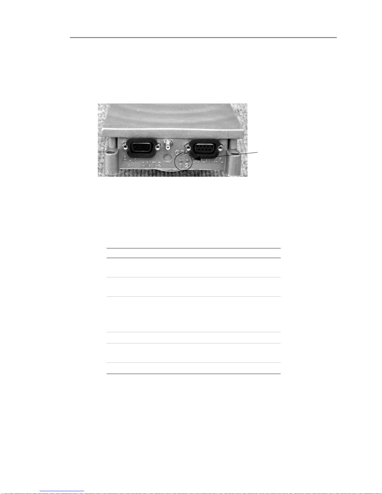
IMPORTANT Make a note of the Dealer code and the SCID code for your
SkyMate 100 SentryMate. You must have this information available when you
install your SkyMate SentryMate software and activate the unit. See Figure 1-2
for the location of the SCID code. You will find the Dealer code listed in your
Quick Start guide and a space to write the SCID code.
Figure 1-2. SCID Code Location
Installing the SkyMate SentryMate Communicator
Typically the Communicator is mounted on a shelf, in a cabinet, or on a bulkhead.
1Place the Communicator on the mounting surface.
IMPORTANT If you are installing the reserve battery on the top surface of the
Communicator (as recommended) perform this step now, before attaching the
Communicator to the mounting surface. This allows you to secure the reserve
battery to the Communicator with the supplied dual lock fasteners.
1
2
3
4
5
6
7
8
9
10
SCID
Code
Location

Release 1.0 CONFIDENTIAL AND PROPRIETARY Installation Guide 7
Installation
Connecting the Serial Cable and the GPS Cable 1
2Attach the flange to the mounting surface.
Installing the Optional Reserve Battery
Typically the reserve battery is attached to the Communicator using the supplied
Dual Lock Reclosable 3M fasteners and cable ties. See Figure 1-3. To install the
reserve battery:
1Place the reserve battery on the top surface of the Communicator.
IMPORTANT Make sure that the reserve battery is oriented to face the power
connector on the Communicator labeled “PWR”.
2Attach the reserve battery to the Communicator’s top surface using the dual
lock fasteners.
3Place the cable ties around the reserve battery and secure the cable ties.
Figure 1-3. View of Installing the Optional Reserve Battery
Installing the VHF Antenna
1Connect the coaxial cable to the base of the VHF antenna using the black tool
provided. (The other end of the cable plugs into the Communicator.)
2Mount the VHF antenna on a standard 1 1/4 inch threaded mount.
There must be a clear view of the sky. You must ensure that no other VHF
antenna (active or inactive) is within four feet (preferably six feet) of the
SkyMate SentryMate VHF antenna.
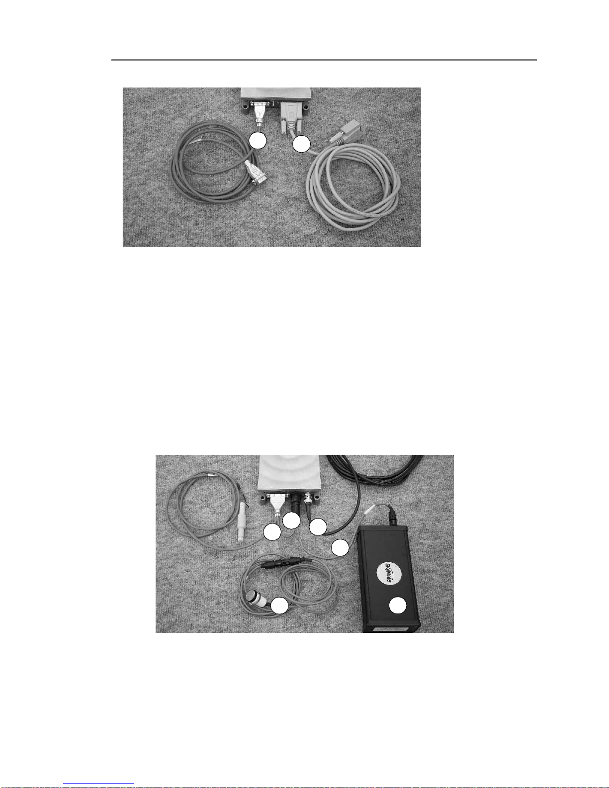
Connecting the Serial Cable and the GPS Cable
1Attach the serial cable (1) to the serial cable connector on the Communicator
marked “Serial”.
2For an external GPS connection, connect the high density 15-pin end of the
GPS cable (2) to the connector marked “AUX”. Connect the standard 9-pin
end to the external GPS device (not supplied).
Installation
Connecting the VHF Antenna Cable and the Main Harness Assembly
1
8Installation Guide CONFIDENTIAL AND PROPRIETARY Release 1.0
Figure 1-4. View of Serial and GPS Cables
Connecting the VHF Antenna Cable and the Main Harness Assembly
The main harness assembly includes cables for power, for the optional reserve
battery, and for the message indicator light. Figure 1-5 shows an overview of the
main harness assembly, the reserve battery, and the VHF antenna cable.
1. Main harness assembly
2. Optional reserve battery
3. Mode control switch and cable
4. Power cable
5. Reserve battery cable
6. VHF antenna cable
Figure 1-5. Overview of Main Harness Assembly, Optional Reserve Battery, and VHF
Antenna
Connecting the Main Harness Assembly
To connect the main harness assembly:
21
1
3
6
4
5
2

Release 1.0 CONFIDENTIAL AND PROPRIETARY Installation Guide 9
Installation
Connecting the Communicator to the PC 1
1Connect the main harness assembly to the connector marked “I/O “on the
Communicator.
2Connect the 4-pin twist lock connector of the main harness assembly to the
connector labeled “PWR”on the Communicator.
3Connect the 2-pin twist lock connector of the main harness assembly (labeled
battery) to the connector on the reserve battery.
Connecting the Power Cable
To connect the power cable:
1Connect the power cable end (from the main harness assembly) to the
connecter marked “PWR”on the Communicator.
Connecting the VHF Antenna Cable
To connect the VHF antenna cable:
1Connect the cable marked VHF antenna to the connector marked “VHF”on
the Communicator.
Connecting the Communicator to the PC
To connect the Communicator to the PC:
1Connect the female end of the serial cable to the serial port on your PC.
❍If you prefer to use a USB cable, you can purchase the USB to Serial
RS-232 DB-9 Adapter Cable accessory. This cable converts a USB port into
a 9-pin male RS-232 port.
Installing the Mode Control Switch
The mode control switch activates and deactivates the monitoring functions of
your SkyMate system. You can install the mode control switch in a spare or
auxiliary rocker switch location if such a location is available, or cut a hole for the
switch.
To install the Mode control switch:
1Select a location such as a spare or auxiliary rocker switch location. If such a
location is not available, go to step 2.
2Cut a rectangular hole 1.45 inches x 0.83 inches hole in a panel or bulkhead and
insert the switch.
3Connect the 3-pin twist lock cable from the main harness assembly to the
Mode control switch by plugging the cable into the 3-pin round connector on
the Communicator cable.
4Connect the mode control switch to the main power/data cable using the 5-pin
round connector. If additional cable is required, eight foot extension cables are
available.

Installation
Connecting the Communicator to the PC
1
10 Installation Guide CONFIDENTIAL AND PROPRIETARY Release 1.0
NOTE The Mode control switch must be installed for your SkyMate 100
SentryMate to work properly.
Installing the Shore Power and the Auxiliary Shore Power Sensors
To install the shore power and auxiliary shore power sensors:
1Attach the shore power and auxiliary shore power sensors to a bulhead within
reach of the cables.
Connecting the Shore Power and the Auxiliary Shore Power Sensors
To connect the shore power and the auxiliary shore power sensors:
1Connect the red wire for the sensor coming from the main harness assembly to
the positive (+) output on the sensor to input terminal 1.
2Connect the black wire for the sensor coming from the main harness assembly
to the negative (-) output on the sensor to input terminal 2.
3Connect your AC power to input terminals 3 and 4.
IMPORTANT If the AC cable run is longer than six inches, we recommend that
you install a 0.5A fuse in the AC cable to protect against faults.
CAUTION When connecting AC power, ensure that the power is turned off.
Connecting the Mode Control Switch
To connect the mode control switch:
1Connect the twist lock connector for the mode control switch to the mode
control cable of the main harness assembly.
See Installing the Mode Control Switch on page 9 for the procedure to install the
mode control switch.
The bilge level sensor detects for water intrusion into your vessel.
1Install the float switch sensor in the bilge area of the boat 4 to 6 inches above
the normal bilge level according to the instructions on the package.
Connecting the Bilge Level Sensor
1Connect the red and white wires to the two grey leads in the bilge sensor. The
bilge level sensor is not polarized. See Figure 1-6.
❍Additional cable should be at least #26 AWG and connections should be
solidly crimped and sealed with shrink-wrap tubing.
❍If the vessel is equipped with an existing bilge alarm, you may connect it to
the SkyMate system in place of the bilge level sensor.

Release 1.0 CONFIDENTIAL AND PROPRIETARY Installation Guide 11
Installation
Connecting DC Power 1
Figure 1-6. Bilge Sensor Connections
Connecting DC Power
Connect your SkyMate SentryMate Communicator to the nearest primary source
of DC power (12 to 24 volts). A typical source is a circuit breaker on the power
panel or a fuse block near the Communicator.
You must consider the following:
❍When connecting to either or these sources, make sure the circuit breaker
or in-line fuse is rated at 3 amps (fast acting).
❍We recommend that you use crimp or lug connectors to connect the power
cable to the DC supply.
❍Special grounding is not required, but it is good marine practice to properly
ground all electronic equipment to the ship’s earth ground system.
CAUTION Reversing the connections described below can damage the
Communicator. Check the polarity with a Voltage Ohm Meter before
connecting the wires.
1Connect the red (+) wire to the positive terminal of the power supply.
2Connect the black (-) wire to the negative terminal of the power supply.
3Connect the SkyMate SentryMate Communicator to ground by running
number 20 AWG wire from one of the mounting screws to the nearest ground
connection point.
4Apply power to the Communicator.
Installation
Installing the Software
1
12 Installation Guide CONFIDENTIAL AND PROPRIETARY Release 1.0
Verifying that Communicator is Operating
Verify that the Communicator is working properly by observing the LEDs on the
side of the unit. If LED 1 is flashing red or amber, the Communicator is currently
searching for a satellite above the horizon. When LED 1 turns green, a satellite is in
view. See Figure 1-7 for the location of the LEDs.
Figure 1-7. Location of the LEDs
Installing the Software
1Insert the CD in the CD drive of your computer. See Table 1-1 for the system
requirements.
2If the Setup.exe file does not begin automatically, navigate to the CD drive
location and open the software folder on the CD. Double-click the setup.exe
file. The setup.exe automatically begins to run.
3Follow the on-screen prompts.
4When the software is installed, a SkyMate icon appears on your desktop. You
can start the SkyMate program by double-clicking the icon, or by going to
Start>Programs>SkyMate.
LEDs
Tab le 1-1. System Requirements
Recommended Minimum
Operating
System
Windows
ME/XP/NT/2000
Windows 98
Browser Internet Explorer 6.0 Internet
Explorer 5.0
Processor 1GHz Pentium III,
Celeron, Duron, Athlon
or equivalent
400MHz
Pentium II,
Celeron, K6 or
equivalent
Memory 256MB Memory 64MB Memory
Screen
Resolution
1024X768 1024X768
Disk Space 250MB 50MB

Release 1.0 CONFIDENTIAL AND PROPRIETARY Installation Guide 13
Installation
Activating Your SkyMate Communicator Account 1
5When you start the SkyMate program, you will see a Welcome screen, as shown
in Figure 1-8.
Figure 1-8. SkyMate Welcome Screen
Activating Your SkyMate Communicator Account
You must activate your SkyMate Communicator account to use your
Communicator’s data services.
1From a computer that is connected to the internet, open Internet Explorer.
NOTE At this time, you cannot activate your account over the Satellite network.
2Enter the following URL in Internet Explorer’s Address field:
www.skymatewireless.com/activation
The Activate Your SkyMate screen opens as shown in Figure 1-9 on page 14.

Installation
Activating Your SkyMate Communicator Account
1
14 Installation Guide CONFIDENTIAL AND PROPRIETARY Release 1.0
Figure 1-9. Activate Your SkyMate Screen
3Enter the dealer code. The dealer code is a seven character alphanumeric code
that uniquely identifies your Communicator. You will find the Dealer code in
your Quick Start guide.
4Enter the SCID code. The SCID code is a Satellite Communicator
identification code that uniquely identifies your Communicator.
An SCID code typically begins with ST25 followed by eight digits. For
example:
SCID2500000000
5Click the Submit button.
6Choose your service plan using the radio button in the next screen.
7Follow the on-screen prompts to accept the terms of the Service Agreement.
8Choose a username.
The username can be any combination of letters, numbers and the dot, dash,
and underscore characters ('.', '-' and '_').
NOTE It is not necessary to enter @skymate.com when entering your username.
The username will be your email address (for example,
username@skymate.com) and will gain you access to the SkyMate web site to
view usage, billing and configuration information.
9Click the submit button after choosing your user name.
10 Follow the on-screen prompts to enter a password. Make a note of the
username.
The password can be any combination of letters, numbers and the dot, dash,

Release 1.0 CONFIDENTIAL AND PROPRIETARY Installation Guide 15
Installation
Coverage 1
and underscore characters ('.', '-' and '_').
11 Click the submit button after choosing your password.
NOTE Make note of your username and password and keep it in a safe location.
12 Follow the on-screen prompts to enter information about your vessel and to
enter your credit card information.
13 Click the continue button after entering this information.
14 Verify that the information you entered is correct. Choose the Complete order
radio button to finish activating your Communicator.
15 The Activation complete screen provides a summary of your order
information. You can print a copy for your records from this screen.
Checking Satellite Availability
To check Satellite availability:
1Go to System>Statistics.
❍The parameter “Satellite Availability”is the average amount of time a
satellite has been in view since the communicator has been powered on or
rebooted.
❍For a reliable measurement, leave the unit powered on for at least 3 hours.
Satellite availability should be greater than 50 percent for reliable service. If
satellite availability is less than 50 percent, check the VHF antenna location
and all coax cable connections.
Coverage
The coverage map in Figure 1-10 identifies where SkyMate services are available.
Please contact support@skymatewireless.com if you plan to leave the area
surrounding the United States, as you must have authorization to receive service in
other locations.

Installation
Coverage
1
16 Installation Guide CONFIDENTIAL AND PROPRIETARY Release 1.0
Figure 1-10. Global Satellite Service Area

2
Release 1.0 CONFIDENTIAL AND PROPRIETARY Installation Guide 17
2Service and Maintenance
Adjustments or Repair
Adjustments require specialized service procedures and tools only available to
qualified service technicians –there are no user serviceable parts or adjustments.
The operator should never remove the cover or attempt to service the equipment.
SkyMate products are supported by the manufacturer. For product information
contact:
SkyMate, Inc.
14000 Willard Road
Chantilly, VA 20151, USA
Telephone: 703-636.4220, Toll free: 866-646-4932
Fax: 703-814-8585
Email: support@ skymate.com.
Maintenance
Your SkyMate Communicator is designed to be virtually maintenance free. Your
attention to a few basic points should assure many years of service.
1. Keep the Communicator as dry as possible.
2. Clean the exterior of the Communicator with a tissue or soft non-abrasive
cloth.
NOTE Do not use solvents or other chemicals for cleaning the equipment.
3. Inspect the case an antenna periodically for any damage.
Requirements and Notices
This section describes the FCC compliance, the safety notice, and maintenance
information.

Service and Maintenance
Contacting SkyMate
2
18 Installation Guide CONFIDENTIAL AND PROPRIETARY Release 1.0
NOTE System requirments are listed in the Installation chapter. You can also
find system requirments on the CD that is shipped with the SkyMate system,
and on the SkyMate Web site at this URL:
http://www.skymate.com/products/system_req.asp
FCC Compliance Statement
This device complies with Parts 15 and 80 of the FCC Rules. Operation is subject
to the conditions that this device does not cause harmful interference. Changes or
modifications to this equipment not expressly approved in writing by SkyMate,
Inc., could violate compliance with FCC rules and void the operator’s authority to
operate the equipment.
Safety Notice
This device is only an aid to operation of your boat. Its performance can be affected
by many factors including equipment failure or defects, environmental conditions,
and improper handling or use. It is the user’s responsibility to exercise common
prudence and navigational judgment, and this device should not be relied upon as a
substitute for such prudence and judgment. Your SkyMate Communicator
generates and radiates radio frequency (RF) electromagnetic energy (EME). This
equipment must be installed and operated in accordance with the instructions
contained in this handbook. Failure to do so can result in personal injury or
product malfunction or both.
Warranty
Your SkyMate equipment is covered by a one year warranty. If the equipment fails
within one year, it will be repaired or replaced. If the equipment requires service,
return it to your authorized dealer or to SkyMate’s Product Repair Center at the
address below:
SkyMate, Inc.
Product Repair Center
14000 Willard Road, #2
Chantilly, VA 20151
Contacting SkyMate
You can contact SkyMate in a number of ways if you need assistance with your
SkyMate Communicator.
Technical Support
Call 1-866-SkyMate or 1-703-636-4220.
Service hours are Monday to Friday from 8am to 6pm Eastern Standard Time. Our
technical support specialists are available to answer installation, operation, and
troubleshooting questions about your SkyMate Communicator.
Table of contents
Other SkyMate Cell Phone manuals


