SlowBipe Air SlowBipe Instructions for use
SlowBipe ARF Construction Manual
This manual will illustrate the construction of the SlowBipe airplane from kit to flight.
Go to www.slowbipe.com/products.asp for a full color version of this manual.
The magnets are already installed. Some of the assembly on this kit is already done. This
manual documents setting up the SlowBipe using the Power Pack and Servo Pack from
SlowBipe.com.
Warning: Do not use CA or Super Glue. Even some “foam safe” cyanoacrylate glues
will attack the blue foam in this kit.
For this build I used Gorilla Glue for everything. Once you learn how much of it to use,
it is one of the strongest and lightest glues you can use. If you have not used it before, do
some test glues on something that you can throw away. Be sure to spread a thin film of
the glue all the way to the edges of what you want to glue. I spread roughly over the
entire surface to be glued, then wipe it to a thin film with a wiper. I am supplying several
pieces of scrap foam to be used as a wiper during construction.
Fuselage Construction
•Using your glue of choice, do the following steps
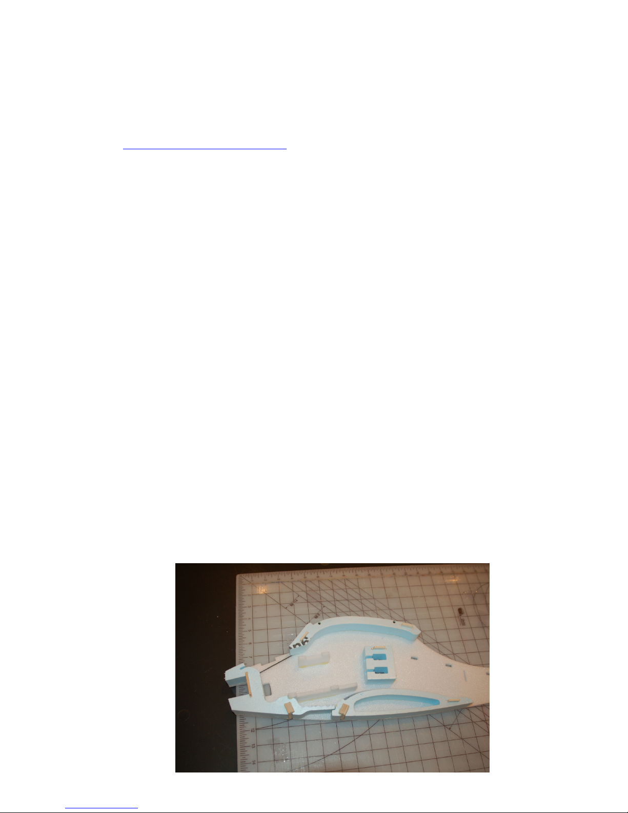
oInsert the 4 included plywood keys into the slots in the 4- one inch thick
fuselage core pieces. The keys then align the core pieces to the locations
they go on the depron fuselage sides. Please see the picture. You can glue
them onto one side now. The four pieces are as follows:
Servo block – Place this so that the slots cut for the servo wires is
on the opposite side of the fuselage from the cutout for the servo’s.
Top Wing Saddle – This piece already has the two magnets glued
into it.
Bottom Wing Saddle – This piece already has a landing gear block
glued in.
Firewall Core Piece – This piece already has the plywood firewall
and a landing gear block glued in.

2
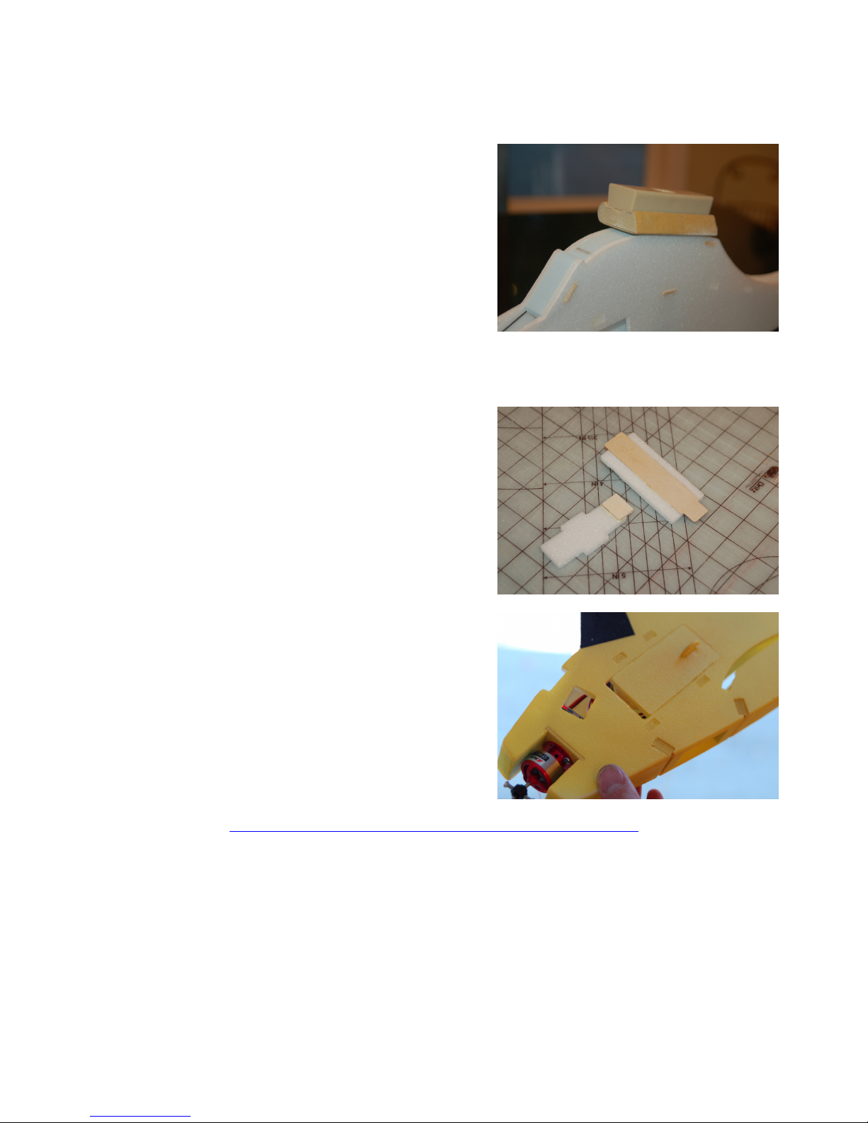
oNow glue the one half inch
thick tail block assembly to the
depron fuselage side. There are
4 alignment tabs to place it
correctly. See picture.
oNext are the battery trays top
and bottom core pieces. These
are cut from 6mm depron foam
and will be glued in on one
side.
oAt this point I would allow
these pieces to dry, but that
really depends on the type of
glue you choose to use.
oIncluded with your kit is a
depron spacer from 6mm foam
that is about 4 x 4 inches. Use
this spacer to raise the tail on
the flat surface to make the
tapered tail. See picture.
oIt is now time to glue in the
6mm depron tail spar. This is
the tapered spar that is tabbed.
Apply glue to the areas that
touch the one fuselage side and
press into place.
oNow apply glue to all of the
surfaces that will touch the
second fuselage side when
installed. Be sure to use the
spreader to make sure that the
Gorilla glue is applied with a
thin film across every surface.
oIf using Gorilla glue I would
then spray the entire surface
with a mist of water and align
and press down the second
fuselage side. Once this is
down apply some form of
weight to the surface of the
plane so that the joint is tight.
oAllow to dry
3
Other Fuselage Items
oGlue the Plywood Pushrod Guide
into slot in fuselage side.
oUsing a sanding block, sand the wing
saddle so that the depron and blue
foam are at the same level. This will
ensure that you get good contact for
the magnets that hold the wing on.
You can also sand any other surfaces
that are not even to create a better
finished plane.
oGlue hatch back plate to back side of hatch door. There is a recessed area
in the 1/32 inch plywood plate for alignment on one edge of the foam
door. See picture.
oGlue hatch door handle in slot in
front of battery hatch door.
oGlue 1/8 inch light ply retainer to
end of fuselage nose hatch. See
picture for placement. There is a
mark milled in the surface of this
foam part. You can align the
plywood retainer to this mark. This
piece slides into the nose block of
the plane to make the hatch cover a
tight fit.
Paint Fuselage
•Optionally paint the fuselage at this time.
The paint that I have found to work the best
that doesn’t eat the foam is Krylon Short
Cuts. I have found this paint locally at
Michaels Craft store as well as Hobby
Lobby.
ohttp://www.krylon.com/products/short_cuts_aerosol_paints/
oSpray one or two light coats and allow to dry over night

4
Battery Hatch Door
oThere is a piece of self adhesive
¼” foam in the kit to go on the
inside of the battery door. When
applied it will hold the door shut
from pressure on the battery pack
inside.
oI would place the Velcro on the
bottom of the battery compartment
floor and on the side of your
battery pack. This makes it easier
to get the battery in and out
without pulling the Velcro off the
surface. It also leaves more space
for the battery pack. See picture 8.
Rudder Assembly
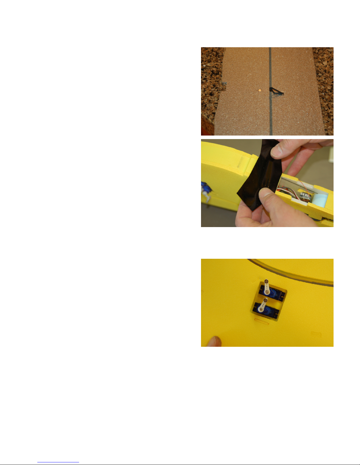
•Using 5 minute epoxy glue rudder shaft into milled slot in foam rudder. 5 minute
epoxy is available at most home improvement stores and at Walmart.
oRudder shaft is oriented so that the hole for retainer clip is at the bottom
and so that the clip when inserted is parallel to the rudder. If you have the
landing gear option, you can use the tail wheel wire here to make sure that
the holes are parallel to the rudder. Tail wheel wire will install through
this hole to make the tail wheel steerable.
•When the rudder shaft is dry in the
rudder, slide rudder control horn onto
rudder shaft from bottom
oRudder control horn is oriented
so that it extends to the right of
rudder when viewed from behind
•Using 5 minute epoxy glue rudder
control horn to shaft and bottom of
rudder
oSee illustration for position of
rudder control horn
oThe control horn will be perpendicular to rudder or 90 degrees
5
Elevator Control Horn Installation
•Using Epoxy glue, glue the control horn
into the two 1/16
th
inch holes on the
bottom of the horizontal stabilizer
oSecure by gluing the retainer on
the other side. The magnet to
retain the stabilizer to the fuselage
is already installed for you.
Windshield Installation
•Remove backing from vinyl windshield
•Apply vinyl windshield to fuselage
•Press windshield sides around fuselage
and press firmly
Servo Installation
•Feed servo wire from servo slot through fuselage and into radio compartment
•Press servo into servo holes by rocking the
servo gently until seated. Be carful not to
crush the foam on either side when
starting servo into hole. The servo's install
with the wires facing front of fuselage.
Control Rod Installation
•Connect your receiver up to the ESC
(Electronic Speed Control) and two
servo’s.
oThe top servo is for rudder and the
bottom is for elevator
oConnect your battery pack to the ESC
oTest that your radio is functioning and allow servo’s to center
6
•Install servo arms onto servo’s with both arms facing down. If you purchased the
servo pack from us, we have attempted to align these for you already.
•Slide horizontal stabilizer into slot in fuselage tail until the magnets align and it
snaps into place
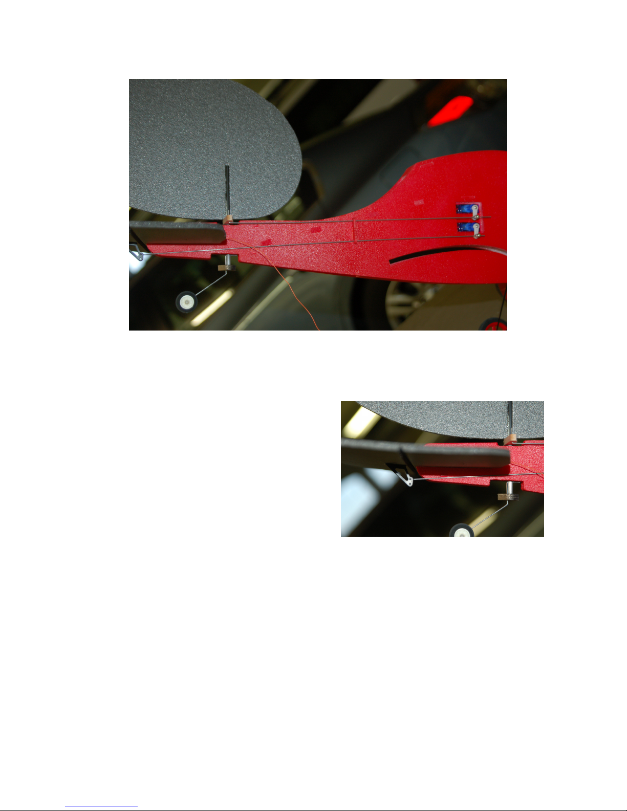
•Insert control rod into rudder control
horn as you install the rudder. Retain
rudder with supplied body clip at bottom
of fuselage, or the tail wheel wire.
•Install wire control rods through pushrod
guide and into EZ Links on servo horns
•Insert control rod into elevator control
horn so that the side of the fuselage
holds the rod in place

7
Prop Saver Installation
•Assemble prop saver by inserting
two screw into prop adapter hub
•Slide prop saver onto motor shaft
per illustration and tight screws
with Phillips head driver.
Wing Assembly
•Drop top wing onto top of
fuselage. It will snap into place
from magnets. After flying, you
can adjust the wing on the magnets
to get the plane to fly straight and
level.
•Be sure to press the leading edge
magnet down firm each time you
assemble the plane to make sure
the magnets have good contact.
•Plug one of each lower wing into
each side of fuselage lower wing
slot. These will snap into place
with the magnets that are already installed in these wings.
•Carefully slide wing struts onto ends of wing panels.
Other Flight Items
•CG location is about 1.5 inches behind the leading edge of the lower wing.
•Go to www.SlowBipe.com for flight instructions

8
Landing Gear Installation
•Install main wheels onto axle shafts
on landing gear legs. Slide ½ inch
fuel tubing onto axes and up against
wheel to retain main wheels.
•Insert landing gear legs into each
side of fuselage by carefully sliding
each rod into the holes in fuselage
gear blocks. They should go in
approximately 7/8 inch.
•Snap gear retaining blocks onto front
set of gear rods by aligning the rods
to the gear pushing the block on
from the front. Slide rear gear
retaining block onto rear set of gear
rods by pushing the block on from
the rear. Gear legs pull down to
align and snap into the blocks. This
ensures that the legs will not pull out
during landing. See picture.
Rudder Installation
•Slide Rudder Assembly into rudder
bearing blocks in tail
•Insert rudder control rod into control horn through pushrod guide and into bottom
of rudder horn
•Retain rudder control rod at bottom with either the body clip or landing gear tail
wire if you are using the landing gear option. See Picture.
Table of contents
Popular Toy manuals by other brands


CYmodel
CYmodel BEAVER CY8043B instruction manual

SAB Heli Division
SAB Heli Division Goblin Kraken Urukay Genesis manual

Carl Goldberg Products
Carl Goldberg Products Stinson 108 ARF user guide

REVELL
REVELL Aces Wild Custom Chopper Assembly manual

POLA G
POLA G Madulain Station manual

Gualala Gadget
Gualala Gadget Small Gear Assembly instructions