manuals.online logo
Brands
  1. Home
  2. •
  3. Brands
  4. •
  5. Gualala Gadget
  6. •
  7. Toy
  8. •
  9. Gualala Gadget Small Gear User manual

Gualala Gadget Small Gear User manual

Assembly Instructions!
!
Follow these instructions to assemble the SMALL GEAR model with pre-soldered electric
component. !
!
You will need a small hex driver, a small phillips head screwdriver, tweezers and, optionally, a
small hobby knife. !
!
Step 1: Check that you have all the parts.!
1. Three printed parts: Maze, Lifting Gear and Motor Gear (all red in this photo).!
2. Two 1.5mm x 5mm motor mount screws, and one 2.0mm battery mount screw. (There!
may be extras in the small bag — the tiny screws are easy to lose).!
3. One 4mm Lifting Gear hex drive screw, which will be the Lifting Gear’s axel.!
4. Motor and Button assembly, already soldered.!
5. Four rubber feet.!
6. Ten 8mm steel bearing balls.!
!
Step 2: Inspect and clean any stray extruded filament from the Maze using tweezers or a small
hobby knife.!
In this picture you can see a small piece of plastic that bridges across the ball track in the Maze.
These randomly occur during the printing process. Follow both tracks looking for these and
remove them with the tweezers. It’s best to do this now before the lifting gear is attached
because it is a little easier to get to them. But, if you don’t get them all you’ll be able to clear
them later when the model is finished.!
!
You can test how clear the tracks are by placing balls on the top and watching them roll to the
bottom. The balls will get stuck where pieces of filament need to be removed. !
!
The plastic parts are durable, but you want to treat them gently, especially the maze. Don’t
squeeze hard when holding it to attach components, and don’t drop it. "
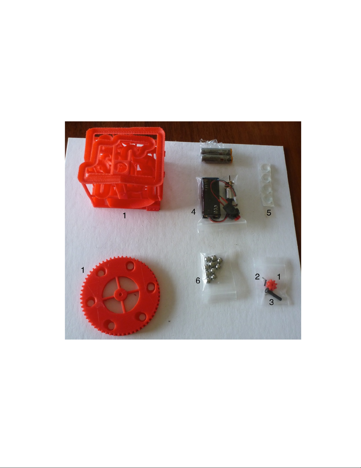
Step 3: Test the electric parts.!!
Carefully connect the motor/battery and button,
insert two AAA batteries and press the button. Make
sure the motor is rotating in the clockwise direction. !
!
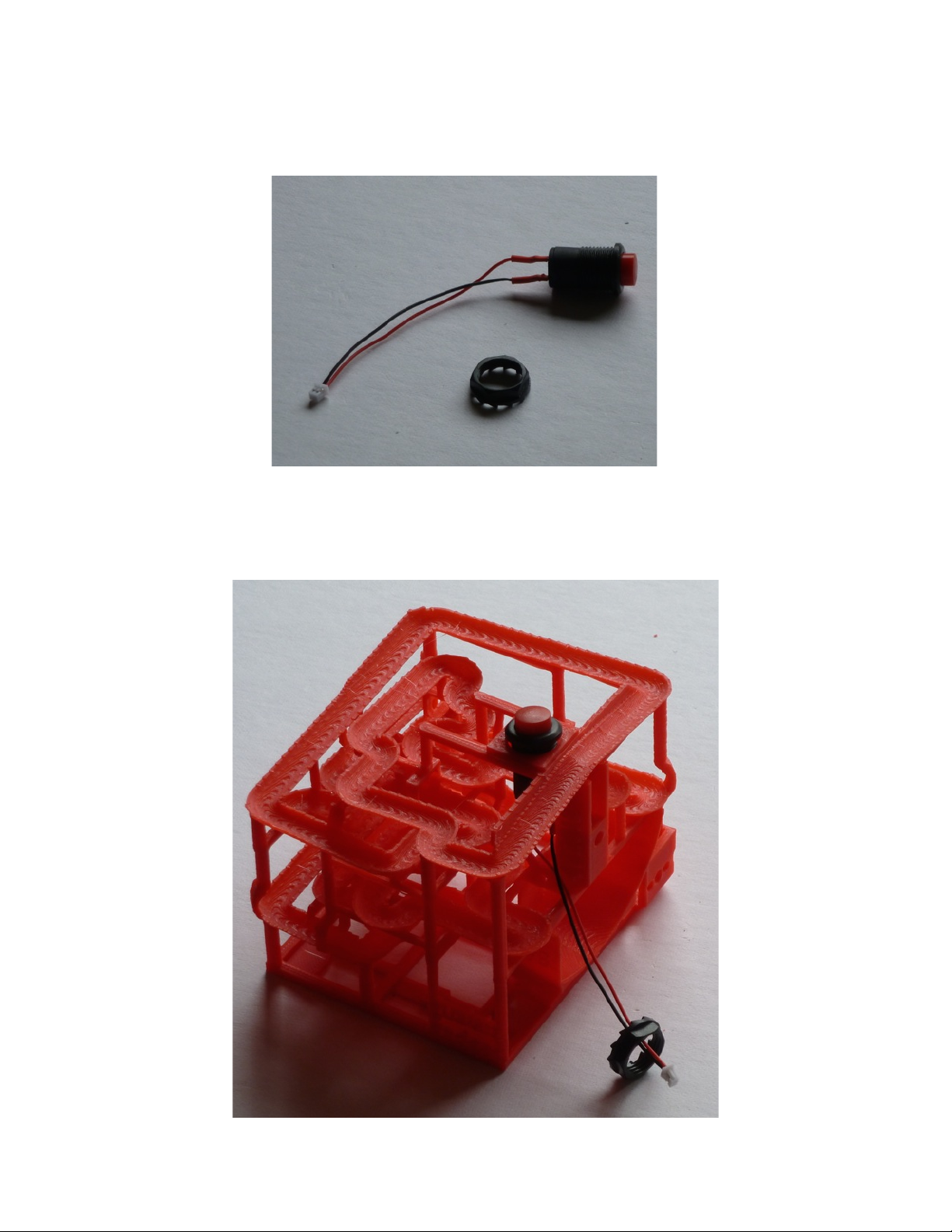
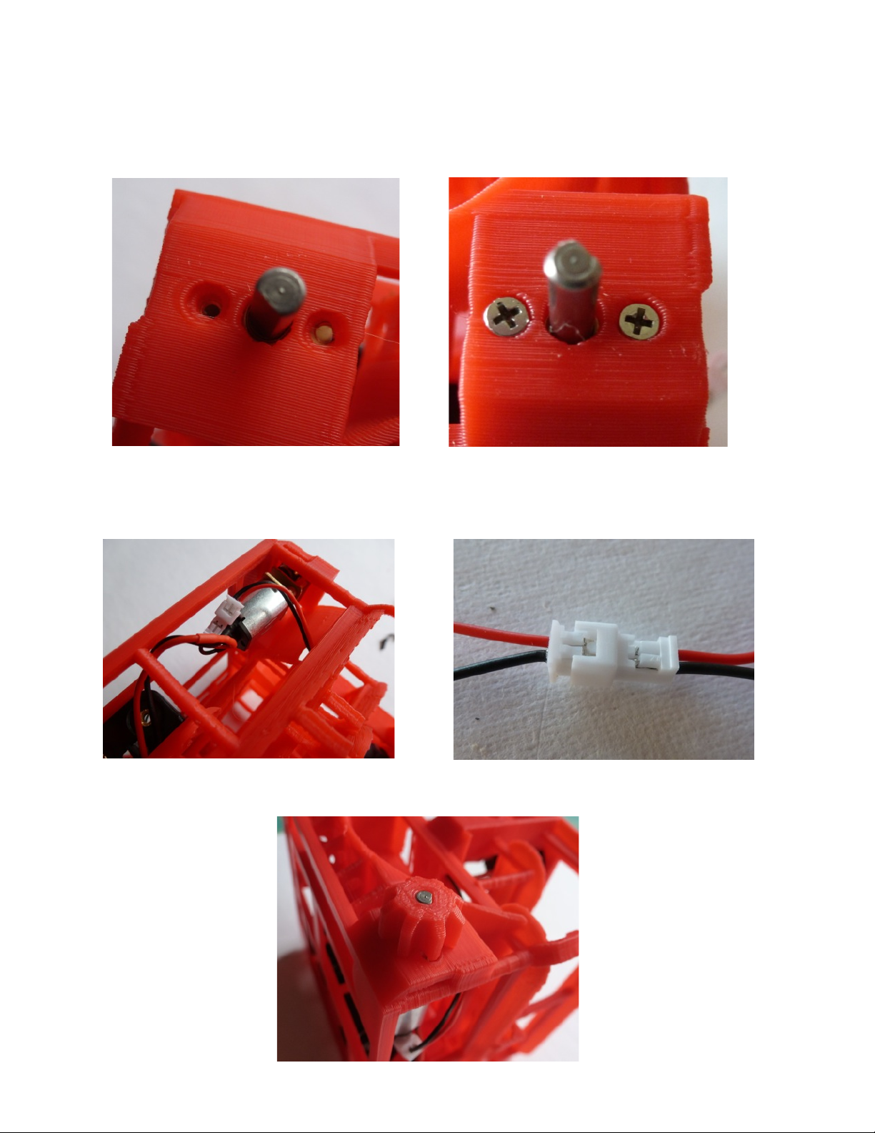
You may find it necessary to use the tweezers to
connect or disconnect the small JST connector. This
is an especially tricky step — you need to be very
careful with this connector. Don’t force it. If you’re
having trouble inspect the socket side and make
sure the pins are properly aligned for the plug side.!
!
If the motor is running backwards make sure the
batteries are correctly inserted.!
!
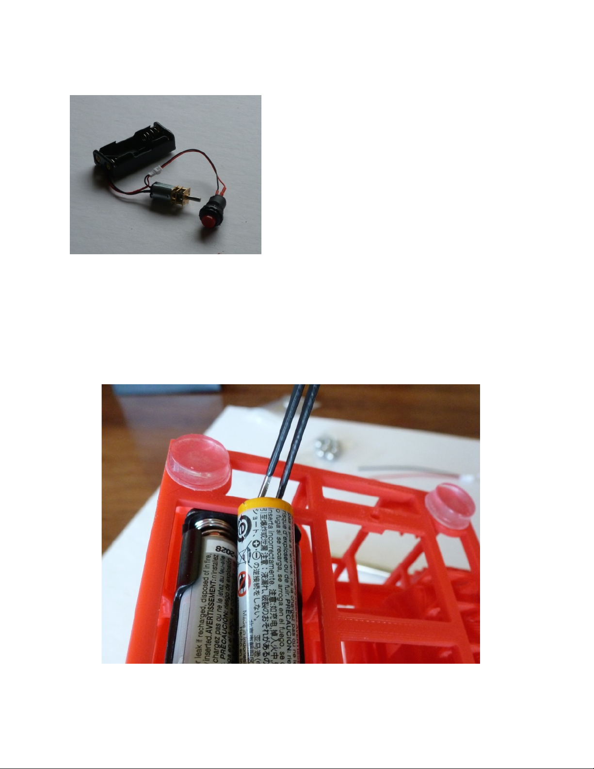
If the motor doesn’t run at all check that the batteries are seated in the holder properly, and use
the tweezers to “kickstart” the motor by spinning the gear closest to the motor in the tiny
gearbox. (Sometimes the motors arrive from the factory in a “stalled” condition, but kickstarting
them seems to solve the problem).!
!
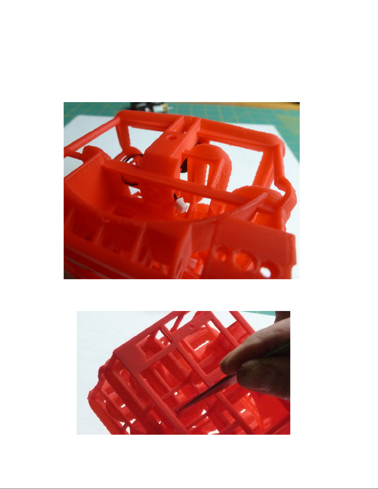
Once you have completed this step, remove the batteries and disconnect the two components.
You can use the tweezers to help remove the batteries. !
!
!
!
Step 4: Remove the nut from the button.!
!
Step 5: Insert the button in the top hole in the Maze, and reattach the nut. It’s easiest to do as
shown routed in this photo, then hold the maze upside down when attaching the nut:"
Step 6: Finger tighten the nut and route the wire through the opening just below the axel
mounting hole, and then turn 90 degrees so that the wires are heading towards the motor’s
mounting location. When properly installed these wires route along the top of the ball hopper,
and exit through the small rectangular hole on the right, just above where the motor will be
mounted. It’s important to route the wires this way to avoid obstructing the balls in the loading
hopper.!
!
Step 7: Use tweezers to clear the motor mount hole, so it will be easier to insert the screw later.!
Step 8: Position the motor and battery assembly by passing the motor through the opening
between the motor and battery locations, on the bottom of the maze.!
!
!
Step 9: Align the battery compartment to its mount hole in the Maze and attach it with the 2mm
(black) phillips head screw (the screw is shown directly below its hole in this photo).!
!
Step 10: Insert the motor axel into the middle hole in the motor mount, and align it so the
motor’s threaded holes are directly behind the holes in the motor mount. Attach the motor to the
Maze using the two tiny silver 1.6mm phillips head screws.!
!
Step 11: Reconnect the motor/battery to the button. Remember to be very careful with this step,
make sure the red and black wires are aligned, and don’t force the connector. !
Step 12: Attach the Drive Gear to the motor axel. The axel and gear are keyed.!
!
Step 13: Using the hex driver screw the 4mm black axel screw all the way into the Lifting Gear,
so that the head of the screw is on the side where the ball lift holes are smaller. This is the side
opposite the one where the balls enter and leave the gear. Make sure that the gear spins freely
on the axel. You need to turn the screw until the self-threads in the plastic are stripped, then
turn it back and forth some. The ideal looseness is when you can spin the gear with one one
hand while holding the axel screw with the other.!
!
Step 14: Attach the Lifting Gear to the Maze. Make sure the 4mm screw is perpendicular to the
Maze when attaching. It will self-tap.!
!
!
Step 15: Tighten this screw all the way, then back off by about one turn. You want as close an
attachment as possible without causing drag on the Lifting Gear. You should have a tiny gap
between the lifting gear and the maze, as shown here:!
!
Step 16: Attach the four rubber feet to the bottom of the model.!
!
Step 17: Your model is now complete. Re-insert the AAA batteries and press the button to turn
the motor on, and add the balls. If the Lifting Gear drags for part of its rotation loosen the axel a
little. You will probably need to do some tuning to ensure the balls roll freely and do not fall off
the tracks.!
!
If balls get stuck, examine the track at that location and look for stray pieces of plastic. You can
easily remove these with the tweezers, or a small hobby knife. If balls fall off the track it’s also
because of small pieces of plastic that need to be removed. These failures are a little harder to
locate if you don’t actually see where the ball left the track, so it may take some patience
watching the model. !
!
If a ball leaves the Lifting Gear too late it is because of stray plastic in the Gear’s lifting
compartment. Find the offending compartment and ensure it is free of plastic. !
!
Enjoy!!
!

Popular Toy manuals by other brands

Eduard Panzer IV Ausf. H schurzen manual

Eduard

Eduard Panzer IV Ausf. H schurzen manual

MTHTrains DDA4OX DIESEL ENGINE operating instructions

MTHTrains

MTHTrains DDA4OX DIESEL ENGINE operating instructions

Radica Games Twinkleberries instruction manual

Radica Games

Radica Games Twinkleberries instruction manual

Jamara Bruni Instruction

Jamara

Jamara Bruni Instruction

REVELL Cromwell Mk. IV Assembly manual

REVELL

REVELL Cromwell Mk. IV Assembly manual

Premier designs Wind Garden Biplane Spinner Assembly instructions

Premier designs

Premier designs Wind Garden Biplane Spinner Assembly instructions

Hasbro Play-Doh DreamWorks Trolls Assembly instructions

Hasbro

Hasbro Play-Doh DreamWorks Trolls Assembly instructions

Eduard Spitfire Mk.Vc landing flaps Assembly instructions

Eduard

Eduard Spitfire Mk.Vc landing flaps Assembly instructions

LEXIBOOK CRB300 - PART 1 manual

LEXIBOOK

LEXIBOOK CRB300 - PART 1 manual

CYmodel Pt-19 instruction manual

CYmodel

CYmodel Pt-19 instruction manual

Faller HALF-TIMBERED TWO-FAMILY HOUSE manual

Faller

Faller HALF-TIMBERED TWO-FAMILY HOUSE manual

Kraftei TO-0880006 user manual

Kraftei

Kraftei TO-0880006 user manual

Eduard Zoom P-40B Tomahawk placards 1/24 quick start guide

Eduard

Eduard Zoom P-40B Tomahawk placards 1/24 quick start guide

MGA Entertainment little tikes STEM jr. BUILDER BOT 647550 manual

MGA Entertainment

MGA Entertainment little tikes STEM jr. BUILDER BOT 647550 manual

K'Nex Education Robot quick start guide

K'Nex Education

K'Nex Education Robot quick start guide

roco H0e operating manual

roco

roco H0e operating manual

Kibri 39566 Mounting instruction

Kibri

Kibri 39566 Mounting instruction

Trix V 160 manual

Trix

Trix V 160 manual

manuals.online logo
manuals.online logoBrands
  • About & Mission
  • Contact us
  • Privacy Policy
  • Terms and Conditions

Copyright 2025 Manuals.Online. All Rights Reserved.